
Abstract
This article, for the first time, presents the generation of Roots rotor tooth profiles based on an Assur-group-associated virtual linkage method. Taking the original Roots rotor as an example, structure and geometry of the Roots rotor are introduced, and based on the principle of inversion, an equivalent virtual linkage is identified for generating dedendum tooth profile of the rotor. Using linkage decomposition associated with elemental Assur groups, algorithm for computing the tooth curve is constructed leading to the explicit expression of rotor profile and the corresponding numerical simulation, verifying the validity of the proposed approach. For demonstration purpose, the virtual linkage method is then extended to the generation of tooth profiles for the variants of Roots rotors with arc-cycloidal curves and arc-involute curves. Integrated with computer-aided design, computer-aided engineering and computer-aided manufacturing software platforms, as well as the three-dimensional printing technology, this article provides an efficient and intuitive approach for Roots rotor system design, analysis and development.
Introduction
Since the Roots brothers patented the Roots blower in 1860, this kind of rotor and its variants have been widely used as air dischargers for diesel engines, pumps and other equipments due to its capability of providing higher and greater air flow compared to a conventional pump. In order to bring greater air flow for a Roots blower, in the past one and a half centuries, different cross-sectional designs have been proposed,1–6 analysed and developed. Ritchie and Patterson 7 investigated the geometry of involute rotors aiming for minimizing leakage. Holmes 8 and Litvin 9 established the mathematical models for the cross sections of the Roots blower rotors with involute, cycloidal and arc tooth profiles. Litvin and Feng 10 proposed computer-aided design (CAD) approach for generating the profiles. Mimmi and Pennacchi11,12 investigated different types of positive displacement rotary pumps and blowers. Liu et al. 13 proposed a sealing index and presented a method for the design of lobe pump with high-sealing property. Furthermore, Tong and Yang 3 proposed the pumping ratio, and Yang and Tong 14 formulated the flow rate functions, leading to the design and profile synthesis of various lobe pumps. 15 Vecchiato et al. 16 developed the rotor cross section as a combination of arcs and a conjugated epicycloidal curve. Yao et al.17,18 investigated the geometry of Roots rotor of arc-cycloidal profile and applied the results to the cutting and milling of three-lobe helix rotors. Using the concept of variable trochoid ratio, Hsieh and Hwang4,19,20 developed Roots rotors of high volumetric efficiency and high-sealing property. More recently, Kang and Vu 5 proposed the epicycloidal-circular-epicycloidal (CEC) rotor profile, and Hsieh 6 applied the elliptical roulette curve to the design of rotary lobe dumps.
Profiles of the cross sections of rotors play crucial role in the Roots blowers. However, according to the literature, most of the derivations for Roots rotor tooth profiles are based on gear geometry and theory which involves establishing body-attached reference systems, equation of meshing and coordinate transformation matrices. For engineers with limited knowledge in gear geometry, such derivations, as those in the treatises of Holmes 8 and Litvin, 9 seem complex to them, but generating displacement curve of a linkage through programming associate with pre-provided Assur-group subroutines appears to be easier for them. They can effectively master and apply the latter approach for Roots rotor profile generating, manufacturing and testing. Therefore, this article proposes an Assur-group-associated virtual linkage method for generating the tooth profiles of Roots rotors of various types. The virtual linkage method has been used in multi-grasp manipulation, 21 haptic manipulation 22 and parallel mechanism synthesis, 23 but no report has been found for its application in generating rotor tooth profiles.
Kempe 24 pointed out that planar curves can be generated by linkages; theoretically, the planar curves in the cross sections of tooth profiles of Roots blowers can be produced by linkages. Hence, this article, for the first time, presents the application of virtual linkage method to the generation of Roots rotor tooth profiles. The principle of inversion, as defined in Ye et al., 25 is used in this investigation, leading to the discovery of equivalent virtual linkages, and programming algorithms associated with Assur-group subroutines are formulated and developed, verifying and demonstrating the validity of the proposed method.
Structure and geometry of a Roots rotor
Figure 1 shows the structure a Roots blower developed in this article. It consists of two rotors, that is, rotor 1 and rotor 2. The ratio of the angular velocities between the two rotors is 1; in the practical applications, this transmission ratio is secured by a pair of equal gears that are mounted on the shafts of the two rotors (see Figure 1). Commonly, the rotors have two or three lobes, and the cross-sectional profiles of the two rotors are identical as illustrated in Figure 2. The general profile of a rotor tooth is formed by two types of curves, that is, the addendum profile curve, for example, curve

Structure of a Roots blower.

Geometry of rotor tooth cross-sectional profiles.
From the above description, it can be found that the key issue to produce the full profile of a rotor lies in the creation of the dedendum curve
Equation of meshing and identification of equivalent virtual linkage
Equation of meshing based on principle of inversion
As shown in Figure 2, when the two rotors work together, the addendum curve of rotor 2 meshes the dedendum curve of rotor 1 and vice versa. The two rotors always rotate in the opposite directions, as they are actually coordinated by a pair of gears with gear ratio 1, such that when rotor 1 rotates about
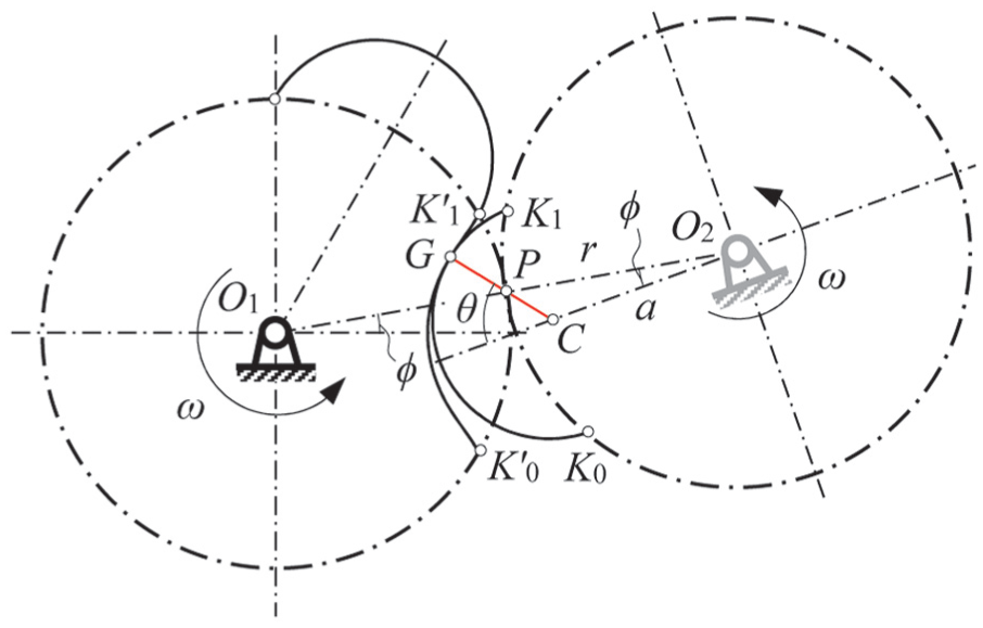
Principle of inversion for generation of curve
Referring to Figure 3, it can be seen that point G is the instant contact point between the two rotors at the current configuration, lying on circular arc
Furthermore, as indicated in Figure 3, according to the law of sine, in

which can be simplified and rearranged in the form of function in terms of variables

It can be found that equation (2) is exactly the same as the equation of meshing of the Roots rotors presented in Litvin’s 9 work, which was obtained through establishing coordinate systems and the complex mathematical derivations based on gear geometry. Therefore, the above derivation of equation (2) based on the principle of inversion not only reveals an efficient and intuitive approach for establishing the equation of meshing for Roots rotor but also verifies the validity of the virtual linkage method presented in this article.
Function equivalence and the virtual linkage
Since point G is the instantaneous contact point between the two rotors, it belongs to both the addendum curve
By carefully observing and analysing the above inverse process, it can be found that point

Equivalent virtual linkage for generating curve
Assur-group-based linkage decomposition and computation of dedendum curve
The analysis of multi-bar linkage is complex if one tries to solve the linkage as a whole system, but the problem becomes easier if the linkage is decomposed into several elementary Assur groups. 27 There are different Assur groups such as Link group, RRR group and RPR group where R stands for revolute joint and P denotes prismatic joint. The formulations and their associated programming subroutines for the elemental Assur groups can be found in Ye et al. 25
According to the Assur groups, the virtual linkage indicated in Figure 4 can be decomposed into two Link groups and one RPR group as shown in Figure 5. One Link group rotates about the fixed pivot
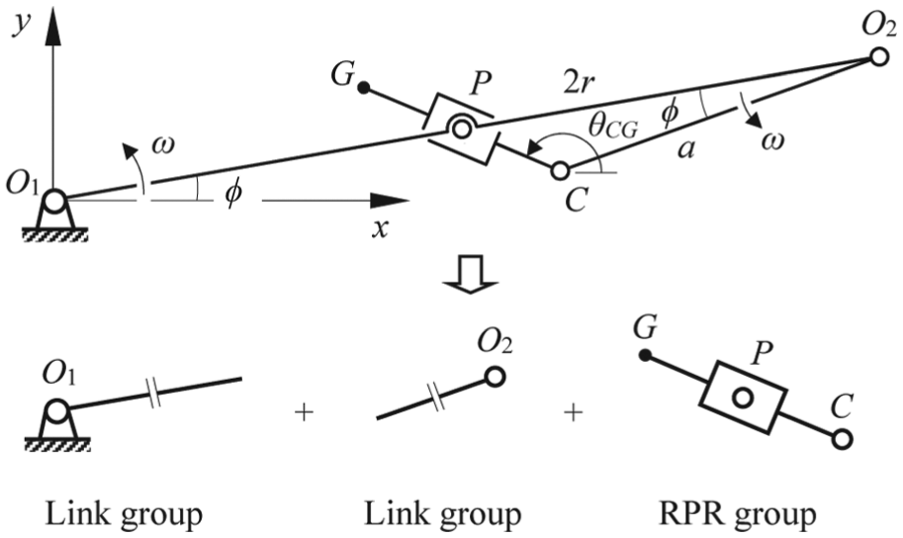
Decomposition of the virtual linkage and the Assur groups.
Based on the Assur groups in Figure 5, using the algorithm in Table 1 which is associated with the subroutines for the Assur groups provided in Ye et al.,
25
the position of point G can be obtained in terms of input angle
Algorithm for computing dedendum curve
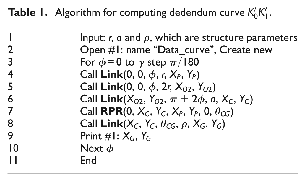
For the algorithm presented in Table 1, three structure parameters r, a and
Based on the symbolic calculation, programme according to the above algorithm explicitly results in the position of point G as

with the structure parameters and angles
The results in equation (3) is, again, exactly the same as the results obtained in Litvin’s derivation based on gear geometry. 9 Thus, we assume that the curves obtained through virtual linkage method is exactly the same as the ones obtained by gear geometry.
By assigning

Generation of dedendum curve

Rotor tooth profiles with various
Extended applications of the proposed virtual linkage method
The virtual linkage method proposed in this article can further be applied to the tooth profile generation for Roots blowers with arc-cycloidal and arc-involute curves.
Generation of arc-cycloidal tooth profile
Figure 8 shows the cross-sectional profiles of a pair of arc-cycloidal rotors. The profiles of the two rotors are identical. In each rotor, the dedendum tooth curve, for example, curve FG in rotor 2, is a circular arc centred at the reference circle of radius r, and the addendum tooth curve, for example, curve AD in rotor 1, is composed of three segments as cycloidal flank AB, a tip circular arc BC centred at point E lying on the reference circle of radius r and another cycloidal flank CD. The two cycloidal flanks AB and CD are symmetric with respect to the line

Geometry of an arc-cycloidal profile and cycloidal curve DC in meshing process.
In this type of Roots rotor, the two circular arcs, that is, the root circular arc and tip circular arc, can be generated straightforwardly; to obtain the completed tooth profile, it relies on the finding of an efficient approach to generate the cycloidal flanks. Taking the cycloidal flank CD in Figure 8 as an example, we use the principle of inversion to investigate the curve in the meshing process. Assuming that rotor 1 is fixed, by rotating

Generation of cycloidal curve through an equivalent virtual linkage.
According to Assur group, the equivalent virtual 2r linkage shown in Figure 9 can be decomposed into two Link groups. It should be pointed out that the virtual 2r linkage can generate the cycloidal flank for theoretical profile as indicated in thick solid line in Figure 9; however, in the practical cases, in order to avoid interference between the two rotors to provide smooth rotation, there is a fine clearance
Algorithm for computing the cycloidal flank.
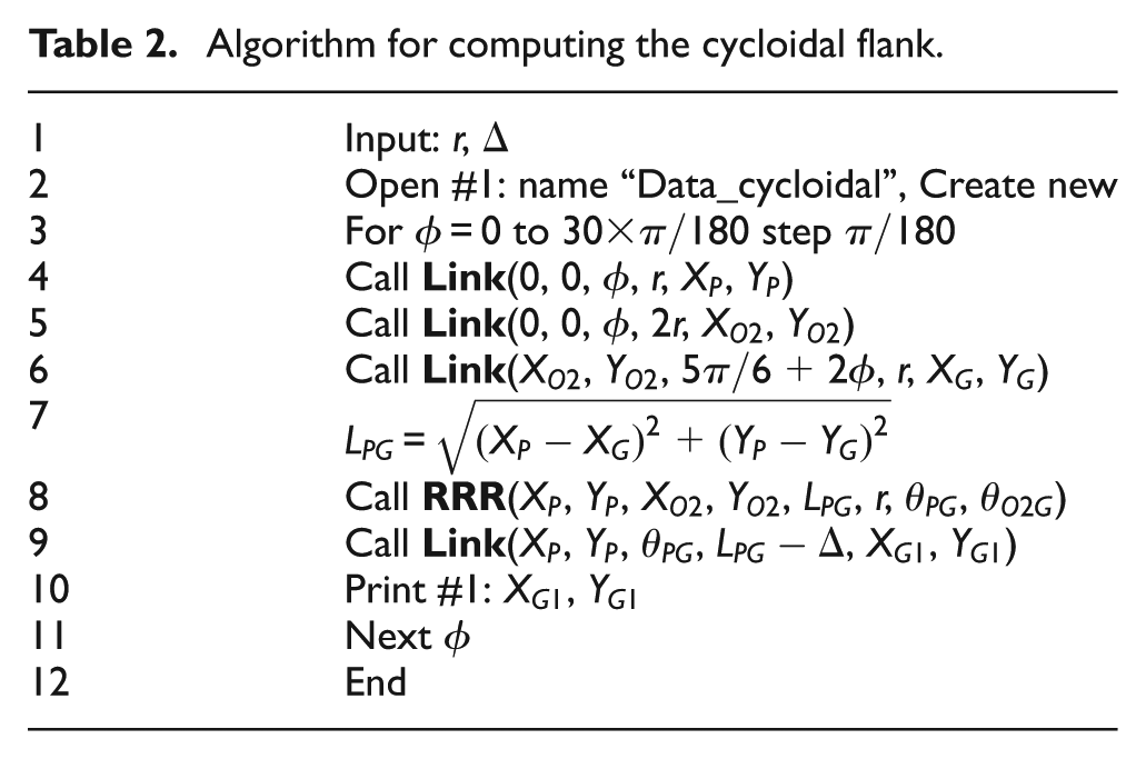
In the algorithm, lines 4, 5 and 6 call the
Symbolic computing of the above programme leads to the implicit expression of the cycloidal curve CD as

with angles
Once curves CD and
Rotor with arc-involute tooth profile
The virtual linkage method can further be applied to the generation of the tooth profile containing involute flank.
Due to its merit of smooth transmission and the mature manufacturing process for involute profile, involute curve is also used in Roots rotor. In such a rotor, the tooth profile contains three curves, that is, the convex tip circular arc AB of radius

Geometry and tooth curves of a involute rotor.
Algorithm for computing the involute flank.
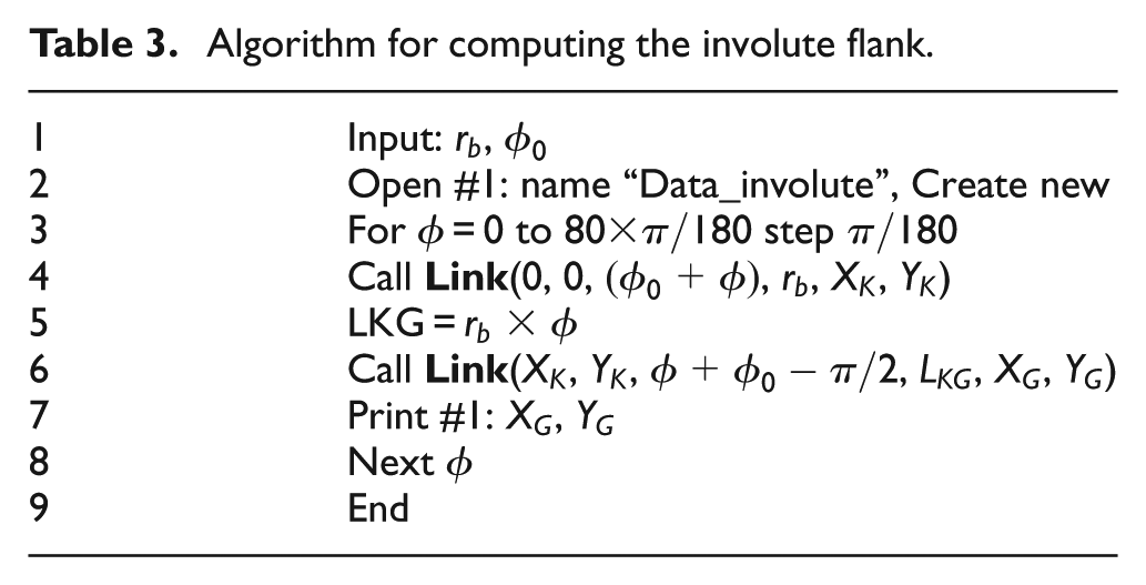
From the symbolic calculation of the above programme, the position of point G can be obtained as

which again verifies the validity of the proposed virtual linkage approach.
Then, based on the geometric constraints and relations presented in Ritchie and Patterson, 7 a numerical example is conducted leading to the completed tooth profile of a involute Roots rotor as shown in Figure 11.

Tooth profile of an involute Roots rotor generated by virtual linkage.
Hence, the Assur-group-associated virtual linkage method presented in this article for the generation of Roots rotor tooth profiles is efficient, and from engineering point of view, it is intuitive. It provides an alternative approach for generating tooth profiles for Roots blowers. Integrating this approach with CAD, computer-aided engineering (CAE) and computer-aided manufacturing (CAM) software platforms, and the emerging three-dimensional (3D) printing technology, this method can lead to better designing, analysis and simulation for Roots rotor systems.
Conclusion
The Assur-group-associated virtual linkage method was, for the first time, applied for the generation of tooth profiles of Roots rotors. By characterizing the geometry and meshing properties of the original Roots rotors, the procedure for identifying the equivalent virtual linkage was presented; then, using linkage decomposition and its association with Assur group, algorithm for calculating the tooth profiles was constructed, leading to the explicit expression of position coordinates of the tooth profiles. Subsequently, the results were compared and verified with those obtained based on gear geometry approach. Numerical example was provided demonstrating the validity of the proposed method. Furthermore, the method was extended to the generation of tooth profiles of the variants of Roots rotors with arc-cycloidal and arc-involute curves. Hence, this article has provided a new, efficient and intuitive approach for the generation of Roots rotor tooth profiles, and considering the programme-based characteristics of the proposed method, it can be integrated with modern CAD, CAE and CAM platforms, as well as the emerging 3D printing technology, providing background for more effective Roots rotor system design and development.
Footnotes
Academic Editor: ZW Zhong
Declaration of conflicting interests
The author(s) declared no potential conflicts of interest with respect to the research, authorship, and/or publication of this article.
Funding
The author(s) disclosed receipt of the following financial support for the research, authorship, and/or publication of this article: This study was supported by the National Natural Science Foundation of China (NSFC) under grant nos 51275092 and 51375013 and the VC ECR scholarship at the University of Salford under grant no. SGGK07.