
Abstract
This article presents an active safety system for a wheeled armored vehicle to encounter the effect of the firing force. The firing force which acts as an external disturbance causes unwanted yaw moment occurred at the center of gravity of the wheeled armored vehicle. This effect causes the wheeled armored vehicle lose its handling stability and the traveling path after the firing condition. In order to overcome the stability problem, a Firing-On-the-Move assisted by an Active Front Wheel Steering system is proposed in this study. This system is developed based on two established systems, namely, Firing-On-the-Move and Active Front Wheel Steering systems. The proposed system is designed to improve the handling and directional stability performances of the armored vehicle while fires in dynamic condition. Four types of control strategies are designed and investigated in this study to identify the most optimum control strategy as the Firing-On-the-Move assisted by an Active Front Wheel Steering system using optimization tool, genetic algorithm. The control strategies for the Firing-On-the-Move assisted by an Active Front Wheel Steering are evaluated using various types of vehicle speeds and firing angle in order to obtain an appropriate control structure as the Firing-On-the-Move assisted by an Active Front Wheel Steering system for the wheeled armored vehicle.
Keywords
Introduction
Armored fighting vehicle is used as one of the important defensive systems in the military application. 1 This type of vehicle is designed using strong extensive armor which acts as a shell to protect the infantry during combats. Meanwhile, the armored vehicle is equipped with a gun turret system for a counter-attack against the enemy.1,2 The gun turret is mounted on top of the armored vehicle in order to produce firepower toward the enemy.3,4 Most of the armored vehicles in military application are designed using caterpillar track configuration for mobility. However, due to its drawback in achieving good mobility and agility, automotive researchers start to focus more in the development of wheeled type of armored vehicle.5,6
The wheeled type of armored vehicle can be categorized as a light or medium weight armored vehicle since this vehicle is less weight compared to the tracked type of armored vehicle. 5 Using a steering mechanism to steer the direction, the weight of the wheeled armored vehicle has been reduced significantly. As consequences, the mobility and handling performance have greatly improved during the battle. Besides, it has increased the possibility of the armored vehicle to accelerate faster compare to the tracked armored vehicle.6,7
However, reducing the weight of the armored vehicle causes major drawback once the wheeled armored vehicle experienced by an external disturbance. 7 One of the major external disturbances affecting the armored vehicle is the recoil forces from the gun turret. The recoil forces disrupt the handling and stability of the armored vehicle while firing in dynamic condition. 8 The recoil force generates unwanted yaw moment which acts at the center of gravity (CG) of armored vehicle. This moment causes the vehicle to yaw in x–y plane and travel out of its desired direction after firing attack.
Therefore, most of the infantry using wheeled armored vehicle avoids firing while in the dynamic position. The infantry performs firing while in a static position or attack in the parallel direction to the traveling path of the armored vehicle.8,9 This can reduce the impact of recoil force significantly before the impact can be transferred to the CG of the armored vehicle and can maintain the handling and stability performance. However, firing in a static position exposes the armored vehicle to an extreme danger situation where the enemies can identify the location of the vehicle. Besides, it will ease the enemy to lock the firing target toward the vehicle. 10
In order to overcome the shortcomings in the wheeled armored vehicle, a lot of active safety systems have been developed by previous researchers. Ahmadian et al. 11 developed firing-out-battery using magneto-rheological (MR) damper. The system is capable of sensing the recoil force and stroke of the gun and providing the optimal damping force for mitigating the recoil energy. Besides, Borkowski et al. 12 and Lin et al. 13 also enhanced their research works on minimizing the effect of recoil forces from the gun turret. An anti-recoil system was able to reduce the impact forces toward the armored vehicle significantly but with limitation such as firing angle in 0°.
Meanwhile, other researchers such as Balla, 14 Galal et al., 15 and Gomez and Ferreira 16 improved the firing accuracy of the gun turret system due to the impact of recoil forces. An automatic target tracking control for the gun turret system is mainly focused on that particular research work. Their active safety systems are mainly focused on stabilization of the gun system to improve the accuracy of firing after affected by recoil forces and uneven road profiles. However, the handling and stability performance of the armored vehicle are still unsolvable using these existing active safety systems. The armored vehicle is unable to follow the desired traveling trajectory due to the external recoil force acting in the lateral direction of the vehicle.
Based on the previous research analysis, it can be observed that the improvement should be considered in the vehicle system itself. Therefore, an active safety system known as Firing-On-the-Move assisted by an Active Front Wheel Steering (FOM-AFWS) system is proposed in this study. This system is proposed as a solution to overcome the existing problem occurred in armored vehicle due to the recoil forces. The system is designed to improve the handling performance as well as to maintain the traveling path of the armored vehicle. The FOM-AFWS is activated once the armored vehicle received external recoil force in lateral direction. This force creates unwanted yaw and lateral acceleration which causes the armored vehicle to lose its handling stability and divert the vehicle from its traveling initial path. The proposed system detects the unwanted lateral motion and provides correction angle to the wheel via Pitman arm steering system. The proposed FOM-AFWS system is designed as the yaw disturbance rejection control for the armored vehicle to counter the effect of recoil force from the gun turret.
This article is organized as follows. The first section represents the introduction and review of some related works on an active safety system for armored vehicle. The following section focused on the modeling the dynamic behavior of armored vehicle model using Newton’s law of motion. The third section represents four types of control structures which are evaluated for yaw disturbance rejection control using FOM-AFWS. The fifth and sixth sections discussed on the genetic algorithm (GA) optimization tool and the performance of the FOM-AFWS control structures for 17-degree-of-freedom (DOF) armored vehicle using various firing angles and speed and finally is conclusion.
Armored vehicle model
The development of an armored vehicle model is very essential to investigate the performance of a vehicle in lateral, longitudinal, and vertical direction. In this study, the development of the armored vehicle is designed using 17 DOFs of non-linear mathematical model. The armored vehicle model, as shown in Figure 1, is developed using integration of few subsystems model to describe the behavior of an armored vehicle. The armored vehicle model consists of 7-DOF ride model, Pacejka’s tire model, 7-DOF handling model, lateral and longitudinal slip model, and 2-DOF Pitman arm steering model. As for armored vehicle system, a gun turret system model is included in the system to study the behavior of the vehicle during firing. The gun turret has 1 DOF due to the rotational motion along the horizontal plane or vertical axis of the weapon platform.

3D armored vehicle diagram.
Ride model
The 7-DOF ride model is developed based on Aparow et al. 17 vertical force equations. Tire vertical behavior is represented as a linear spring without damping, while the wheel model is developed with linear and damping as shown in Figure 1. The armored vehicle body is lumped into a single mass represented by a shell mass and the displacement in the vertical direction is ignored since the armored vehicle is assumed to travel on even road profile. The armored vehicle remains grounded at all times and the four tires always in contact with the ground. The equation of the 7-DOF model is represented as follows


where

and


where
Pacejka’s “Magic” tire model
Several tire models can be used to investigate the performance of tire model. One of the tire models is known as Pacejka’s “Magic” tire model. This tire model is used to define the lateral and longitudinal tire forces as well as tire moment in each tire of the armored vehicle. The general equation of the tire model is described as follows

The term y(x) represents the value of the cornering force, self-aligning torque, or braking force. The model parameters B, C, D, and E represent stiffness factor, shape factor, peak value, and curvature factor, respectively, and defined using normal forces from equations (8) to (11) and lateral and longitudinal slip. Meanwhile, x denotes slip angle or skid based on slip angle, α (lateral direction) or slip ratio, and λ (longitudinal direction). The detailed explanation of the tire model can be obtained from Aparow et al.7,8
Handling model
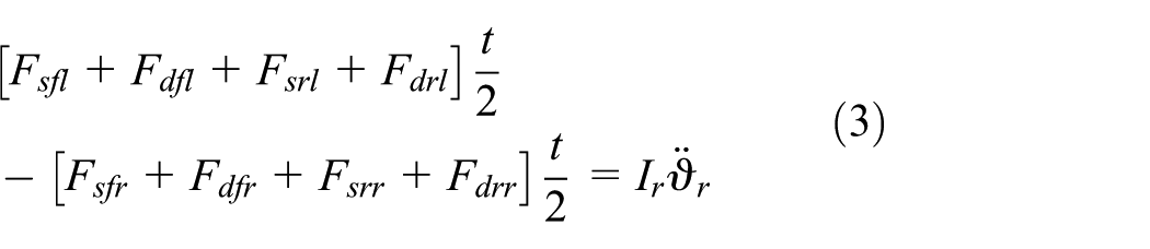
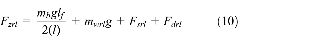
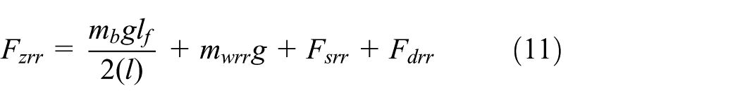
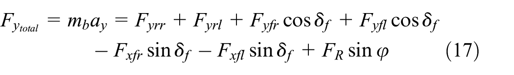
The handling model as shown in Figure 2 is developed for wheeled armored vehicle to describe the lateral dynamic performance of the vehicle. The handling model can be defined as 7 DOFs where 3 DOFs are expressed in the lateral, longitudinal as well as the yaw motion of the armored vehicle. The 3 DOFs of motion are measured in terms of lateral, longitudinal, and yaw accelerations which occurred at CG of the armored vehicle. The total forces acting at the lateral and longitudinal direction of each wheel need to be considered to obtain the lateral and longitudinal acceleration. In order to compute longitudinal acceleration,

where

where

and

where
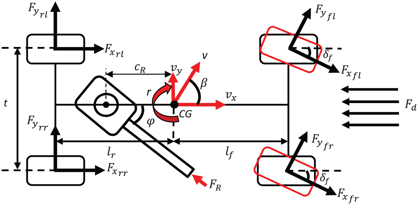
7-DOF handling model.
The yaw acceleration,

Meanwhile, 4 DOFs explained on the rotational motion of the wheel which donates single DOF from each tire. The angular speed of the vehicle,


where

Pitman arm steering model
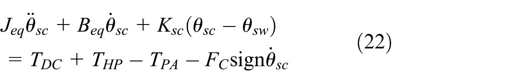
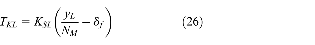
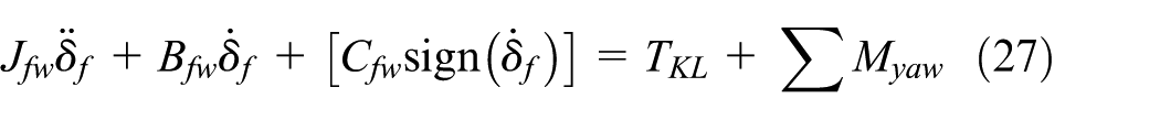
The Pitman arm steering system is mainly used in wheeled armored vehicle. This steering system can be represented as 2-DOF equation of motion using Newton’s second law of motion. This steering system is developed using steering column, universal joint, hydraulic assisted pump, worm gear, sector gear, and Pitman arm joint. In order to control the steering correction using FOM-AFWS, an additional electric motor is included in the steering system. The equation of rotational motion of steering wheel is
where

and

where

where
where
where
FOM-AFWS control design
Two types of control loops are mainly required in the development of the FOM-AFWS. The control loops are known as inner and outer control. The inner loop is designed using the 2-DOF Pitman arm steering model as discussed in the previous section. Meanwhile, the outer loop control is designed using the 17-DOF armored vehicle model. In this study, four types of control algorithms of outer loop control are designed and analyzed. An appropriate control algorithm needs to be identified based on the dynamic performance of the armored vehicle to minimize the unwanted yaw motion due to the firing effect.
Inner loop control design
In the development of inner control as shown in Figure 3, two models need to be controlled which are the Pitman arm steering system and the electric DC motor. Thus, two conventional controllers, proportional–integral–derivative (PID), are used to control the rotational angle of the steering column and the shaft of the electric DC motor. The sole purpose of developing the inner loop model is to control the wheel angle by actuating the steering system and electric motor in order to follow the desired input trajectories from the outer loop control model. Figure 3 shows the inner loop control design for the FOM-AFWS system. The model has been verified using various types of trajectory inputs before it can be implemented in the outer loop control. The verification is essential to evaluate the effectiveness of the inner model which will be used in FOM-AFWS. The validation results can be referred in the work by Aparow et al.8,17
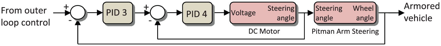
Inner loop of Pitman arm steering model. 8
Outer loop control design
The outer loop control plays an important role to maintain the stability and directional path of the armored vehicle. The dynamic performance of the armored vehicle in lateral motion is considered throughout this study since the impact of gun recoil is maximized in this direction. The lateral motion, such as yaw rate, yaw angle, vehicle body sideslip, and lateral displacement of the armored vehicle, is exaggerated due to the recoil force. Therefore, the outer loop control is developed mainly to improve the lateral performance of the armored vehicle. Four types of control strategies have been designed to investigate the performance of the armored vehicle after the firing effect. The control strategies are designed using double feedback loops for the outer loop control. The purpose of using double feedback loops is to improve the stability as well as to maintain the directional path of the armored vehicle after the firing situation. The control strategies are described as follows and the control structures for each case are shown in Figure 4.

Four types of control strategies using FOM-AFWS for armored vehicle: (a) FOM-AFWS using yaw rate with vehicle sideslip feedback, (b) FOM-AFWS using Estimated Yaw and Lateral Force Rejection Feedback (EsYLaR), (c) FOM-AFWS using Estimated Firing Moment with Summation of Moment as Reference (SuM-FiME), and (d) FOM-AFWS using Estimated Firing and Yaw Moment with Summation of Moment as Reference (SuM-FYME).
Case 1: FOM-AFWS using yaw rate with vehicle sideslip feedback
The outer loop control is designed using a yaw rate feedback followed by an additional feedback loop using a vehicle body sideslip angle. This control algorithm is categorized as the disturbance rejection control since the target of this system is to cancel out the unwanted yaw motion. The yaw rate feedback is used to enhance the stability performance of the armored vehicle; meanwhile, the vehicle sideslip feedback is used to maintain the directional path of the armored vehicle after the firing. An additional gain,
Case 2: FOM-AFWS using Estimated Yaw and Lateral Force Rejection control
As for the second control strategy, an estimated value due to the firing force is used to develop Estimated Yaw and Lateral Force Rejection (EsYLaR) embodiment. The EsYLaR embodiment is used to further improve the overall handling performance of the armored vehicle due to the firing force in lateral direction. The output from the armored vehicle model is measured analytically in terms of lateral acceleration,

Wheeled armored vehicle with two imaginary skyhook wall and dampers: (a) armored vehicle with lateral forces and (b) imaginary skyhook damper configuration.
The EsYLaR embodiment operates by suppressing unwanted lateral forces acting at front and rear of the armored vehicle. The unwanted lateral forces are adjusted using the skyhook damper forces,

where


and

The estimated lateral forces,
The terms
Firing test analysis.

Referring to Table 1, a relationship between lateral force and yaw rate due to the firing force is developed as shown in Figure 6. Based on Figure 6, the relationship shows that the lateral force at the CG is proportional to yaw rate due to the firing force. According to this relationship, a second-order polynomial equation is developed which is as follows


Relationship between yaw rate and lateral force.
Thus, the estimated yaw rate of the armored vehicle can be formulated as follows

The estimated yaw rate and lateral force which are shown in equations (18) and (24) are the output of the embodiment and feedback to the control algorithm of Case 2 FOM-AFWS.
Case 3: FOM-AFWS using Estimated Firing Moment with Summation of Moment as Reference
The third control algorithm is developed based on a target tracking system control method based on Figure 7. A desired target input is developed so that the armored vehicle is able to follow the pre-set target. In this algorithm, the desired target refers to the summation of moment acting on the armored vehicle during firing. Therefore, summation of moments acting at front, rear, and center body is used as the reference set point.
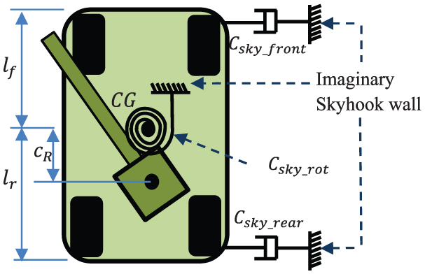
Wheeled armored vehicle with additional rotary skyhook dampers.
By referring to Figure 5, the armored vehicle is designed with linear type of imaginary skyhook dampers which are attached at front and rear of the armored vehicle. As an additional improvement, a rotary type of imaginary skyhook damper is fixed at the CG of the armored vehicle as shown in Figure 7. Based on the skyhook dampers configuration, the summation of moment acting at the CG of the armored vehicle can be identified

By referring to equations (19) and (20),


Meanwhile,

In terms of outer loop control design, this system uses firing moment feedback control loop to maintain the directional path as well as the stability performance. The firing moment from the armored vehicle is estimated based on the yaw rate response due to the firing force. Table 2 shows the simulation test analysis between firing moment and yaw rate response.
Analysis between firing moment and yaw rate.
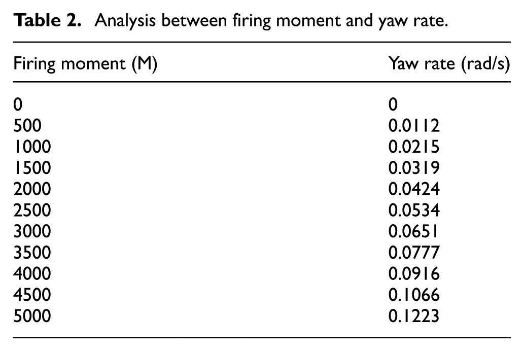
According to Table 1, a relationship between the firing moment and yaw rate has been plotted as shown in Figure 8.

Relationship between firing moment and yaw rate.
Based on the above results, the yaw rate due to the firing is proportional to the moment occurred due to the firing impact. Thus, a second-order polynomial equation is developed to describe the relationship between yaw rate and the firing moment

Then, the firing moment is feedback to the outer loop control as shown in Figure 4. The constant parameters of
Case 4: FOM-AFWS using Estimated Firing and Yaw Moment with Summation of Moment as Reference
The fourth control algorithm is designed based on the combination of the third control strategy with additional looping of estimated yaw rate. The estimated yaw rate is used based on the expression shown in equation (24). The purpose of using additional looping of estimated yaw rate is to further enhance the stability of the armored vehicle which is effected by the recoil force of the gun turret system. Meanwhile, the estimated firing moment feedback loop is mainly used to improve lateral dynamic performance and also guide the direction of the armored vehicle back to its initial traveling path. The estimated firing moment can be obtained from equation (30), meanwhile, the summation reference refers to equation (25).
Optimization tool using multi-objective GA
The control strategies which have been discussed in section “FOM-AFWS control design” consist of two conventional controllers, proportional–integral (PI) and PID, to optimize the outer loop control. The PI and PID controllers used in the control strategies can be derived mathematically as shown


where
where

All the control parameters and the skyhook damper constants,
Yaw rate,
Yaw angle,
Lateral displacement,
Vehicle body sideslip,
All the parameters of the FOM-AFWS are optimized until the dynamic performance of the armored vehicle is improved during the firing process. However, the adjusted parameters using trial and error technique need to be verified using more established approach. Therefore, an optimization tool namely GA technique is used to tune the control parameters. The purpose of using GA tool is to minimize the error by optimizing the control parameters and skyhook damper constants. Since there are two feedback loops in the outer loop control to be considered, this approach can be treated as multi-objective optimization procedure. The GA conditions are set up based on the trial and error approach as discussed in Kusagawa et al. 20 The GA has been developed using MATLAB Simulink software. The parameter values used to define the GA are population size, selection method, fitness value, upper and lower bound, stopping criteria, and mutation and crossover levels. The parameters of GA process set in the MATLAB Simulink are given as follows:
Population size = 500; Selection method = Tournament; Stopping criteria = 1000 generations; Fitness value < 0.00001; Mutation level = Default; Crossover level = Default; Upper bound = 50; Lower bound = 0.
However, the number of variables is very much independent of the design of each control structure. For Case 1, seven variables are required to optimize which are

Flowchart of optimization process using GA.
The optimization process initiates by assigning a random number of variables to each entity in the population. The process continues by simulating control structures, and responses of the armored vehicle in lateral direction are observed. Based on the responses, the algorithm evaluates the fitness score for each entity and carries out selection processes for the parameters. The fitness score is used to ensure the convergence point of the iteration process. Since this is a multi-objective optimization, multiple optimized points will be found, and these points are called as Pareto points. The optimization process is carried out if the generation does not obtain the optimum point. The algorithms continue using the fittest entity and proceed with the mutation and crossover levels in order to determine the suitable parameters in the following generation. The process is approached to a stopping condition once the convergence point is obtained. The parameters after the final iteration are used as the optimized parameters for each control structure iteration.
Performance evaluation of FOM-AFWS
This section discussed the performance of the four types of FOM-AFWS control strategies as described in previous section. The control strategies are investigated based on the lateral dynamic performance of the armored vehicle due to the firing impact. The armored vehicle is assumed to travel at a constant speed of 40 and 60 km/h in longitudinal direction without any steering input from the driver. A single firing is performed toward the enemy in lateral direction. Two types of firing angles, 45° and 90°, are used to produce a firing attack. Since this armored vehicle is categorized as light weight armored vehicle, 75 mm KwK 42, German made gun has been used in the simulation analysis. 7
Simulation parameters
The simulation was performed for a period range of 5–10 s using Runge–Kutta solver with a fixed step size of 0.001 s. The numerical values of the 17-DOF wheeled armored vehicle model parameters are set based on Kadir et al., 18 while the gun model parameters are based on 75 mm KwK 42 caliber size 7 as shown in Table 3.
Parameters of 17-DOF armored vehicle.
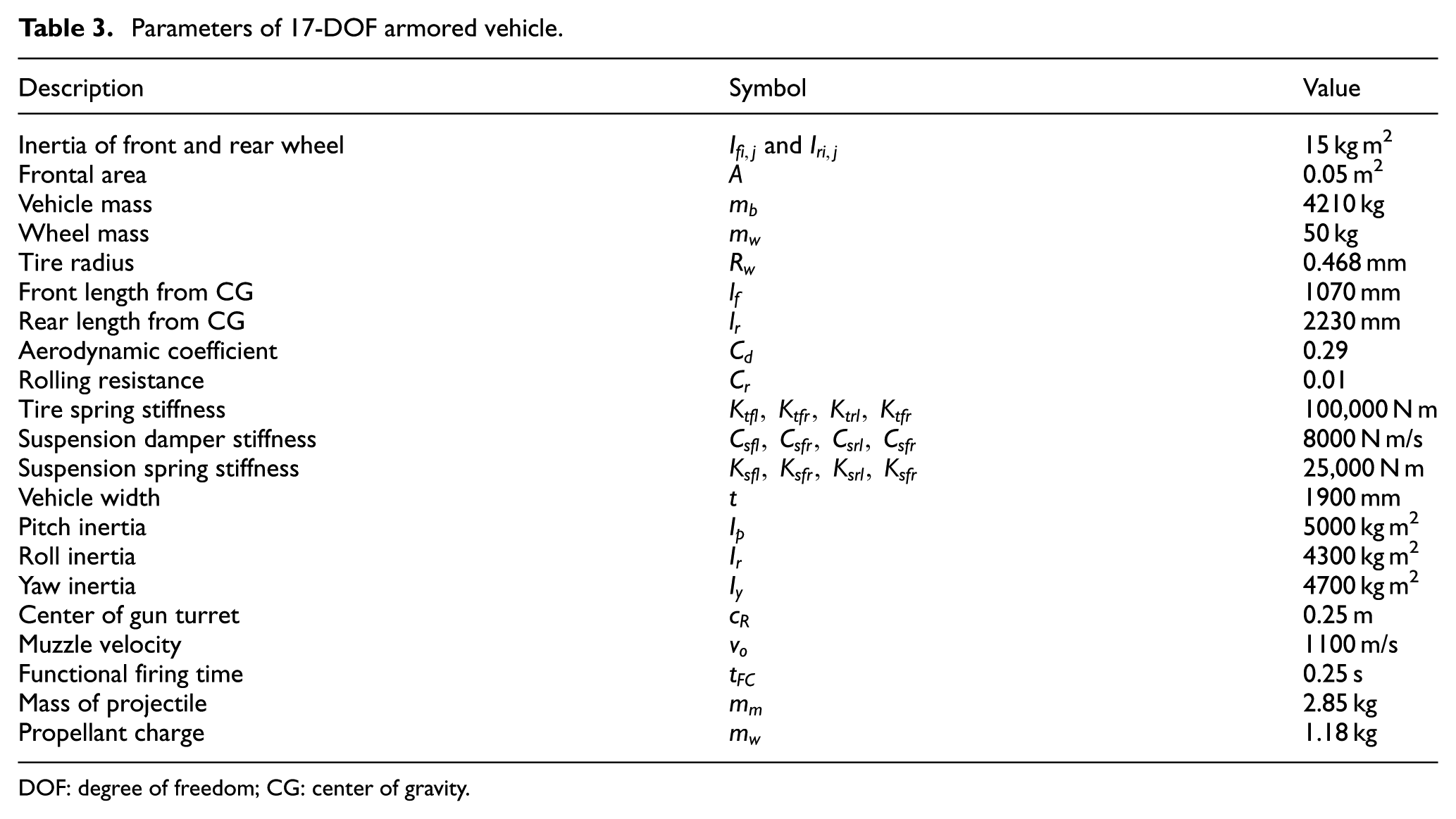
DOF: degree of freedom; CG: center of gravity.
Simulation results
The simulation results show the performance of the armored vehicle during firing in lateral direction. The gun firing was applied at t = 1.5 s and produce recoil force in lateral direction. The maximum recoil force obtained from the 75 mm caliber at 90° is 41.3 kN, meanwhile, at 45° is 29.4 kN. Each firing angle is tested for two types of vehicle speeds, 40 and 60 km/h. The developed control structures of FOM-AFWS are verified based on both firing angle and vehicle speed. An optimum FOM-AFWS control strategy to overcome the effect of firing is identified based on the performance evaluation. The optimum control strategy is used to encounter the unwanted yaw effect due to the recoil force while the armored vehicle firing in dynamic condition.
Vehicle speed at 40 km/h; 45° firing angle
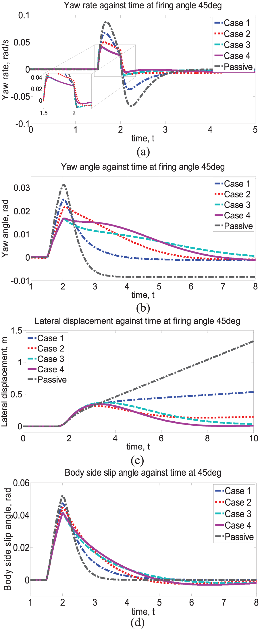
In this condition, the armored vehicle is traveling in longitudinal direction at constant speed of 40 km/h. Then, the armored vehicle performs the firing attack using a 75 mm caliber at a firing angle of 45°. By implementing the FOM-AFWS control strategies, the performance of the armored vehicle in lateral motion is investigated for this condition. The response of the armored vehicle which is equipped with FOM-AFWS is compared with the conventional armored vehicle. The performance of the armored vehicle is analyzed in terms of yaw rate, yaw angle, body sideslip, and lateral displacement as shown in Figure 10(a)–(d).

Effect of firing at 45° at a speed of 40 km/h: (a) yaw rate against time, (b) yaw angle against time, (c) lateral displacement against time, and (d) body sideslip angle against time.
Based on Figure 10(a)–(d), the performance of armored vehicle with FOM-AFWS shows great improvement compared with conventional armored vehicle. In terms of yaw rate response, FOM-AFWS using Case 4 shows positive improvement compared with other cases. The yaw rate magnitude has been reduced from 0.073 to 0.035 rad/s. Similarly, FOM-AFWS in Case 3 also shows good improvement in terms of the yaw rate response which is 0.041 rad/s with minor fluctuating after the firing impulse. This causes an armored experienced unstable situation compared to Case 4. By comparing both Case 3 and Case 4, it can be observed that yaw angle using Case 4 is reduced almost 42%, meanwhile, Case 3 has minimized up to 36%.
There is a slight increase in yaw angle for Case 4 starting from third second to fifth second. This explains the counter-response of the armored vehicle to travel back to its initial position by providing external steering input as shown in Figure 10(c) using the FOM-AFWS control algorithm. Besides, Case 1, Case 2, and Case 3 have improved the directional path after the firing but unable to re-position back the armored vehicle to initial direction path. The vehicle body sideslip also has improved compared with conventional armored vehicle as shown in Figure 10(d). The response of body sideslip has reduced using Case 4 even though the FOM-AFWS control strategy does not consider vehicle sideslip angle as the feedback loop.
Vehicle speed at 40 km/h; 90° firing angle
For second condition, the speed of the armored vehicle is maintained at 40 km/h. However, the firing angle has been increased up to 90°. This firing angle is known as critical angle because the moment created at the CG of the armored vehicle at this angle is large compared with previous condition. Likewise, the armored vehicle has been tested using all four FOM-AFWS cases to identify the most optimum control strategy in order to be implemented in the armored vehicle as active safety system as shown in Figure 11(a)–(d).

Effect of firing at 90° at a speed of 40 km/h: (a) yaw rate against time, (b) yaw angle against time, (c) lateral displacement against time, and (d) body sideslip angle against time.
Figure 11(a) shows the performance of the armored vehicle in terms of yaw rate response. It can be identified that by increasing firing angle, the effect of firing has increased the unwanted yaw motion of the armored vehicle to 0.098 rad/s. However, Case 3 and Case 4 are able to minimize the yaw rate response until 0.044 and 0.041 rad/s, with minor chattering occurring in Case 3 only. As per previous analysis, Case 4 is able to stabilize back the armored vehicle earlier than Case 3 which can be observed in Figure 11(a) at t = 2 s until t = 3 s.
Meanwhile, for yaw angle response, the four cases show significant improvement compared with conventional vehicle as shown in Figure 11(b). The FOM-AFWS of Case 3 and Case 4 show high reduction up to 53% compared with other cases, which are 24% for Case 1 and 34% for Case 2. Similar to the previous condition, an additional yaw angle occurred in Case 4 where it shows the direct response from correction steering input. This steering input is provided to re-position back the armored vehicle to its traveling path after the firing at 90° as illustrated in Figure 11(c). For Case 1, the direction of the armored vehicle is maintained at 0.4 m without any reduction to its initial location.
In Case 2 and Case 3, the armored vehicle is able to stabilize after firing. Unfortunately, the armored vehicle is incapable of maintaining directional path to desired position. Even though Case 3 shows good response in terms of yaw rate and yaw angle, the armored vehicle takes longer time to minimize the effect of recoil force. The improvement can also be observed in the body sideslip angle of the armored vehicle. FOM-AFWS control strategy using Case 3 and Case 4 shows remarkable response compared with the other two cases. This explains that the feedback loop using the estimated firing moment as outer loop control plays important role in improving the dynamic performance of the armored vehicle to reject the unwanted yaw motion due to the firing impulse.
Vehicle speed at 60 km/h; 45° firing angle
As for the third condition of firing on the move application, the velocity of the armored vehicle has been increased to 60 km/h and performs the firing at 45°. It can be observed that the effect on the armored vehicle due to the recoil force is identical to the previous condition which was tested using 90° firing angle at constant speed of 40 km/h. The overall performance of the armored vehicle by implementing FOM-AFWS has successfully attenuated the unwanted effect due to recoil force. The yaw motion response as shown in Figure 12(a) and (b), which is yaw rate and yaw angle, is minimized at least 35% using Case 1 control algorithm. Meanwhile, Case 3 and Case 4 have intensely enhanced the handling performance of the armored vehicle up to 51% by reducing the shortcomings occurred during backward impulse.
Effect of firing at 45° at a speed of 60 km/h: (a) yaw rate against time, (b) yaw angle against time, (c) lateral acceleration against time, and (d) body sideslip angle against time.
However, in terms of the directional path of the armored vehicle, overcoming the effect of unwanted yaw motion at CG of the armored vehicle is mainly achieved using Case 4 control algorithm. It can be observed from Figure 12(c) that the armored vehicle is able to stabilize and return back to its initial position at seventh second after the firing. Meanwhile, Case 3 FOM-AFWS control algorithm takes up to 10th second to reach minimum displacement with a minor gap occurred between initial positions. Case 2 is able to maintain its stability at sixth second but unable to reach the initial position as shown in Figure 12(c). Again, Case 1 is unable to reduce its direction path to desired position after the firing even though the dynamic performance has been improved compared with conventional armored vehicle. Thus, it clearly explains that the necessity of additional feedback loop which is developed by estimating the firing and yaw moment occurred due to the recoil force.
Vehicle speed at 60 km/h; 90° firing angle
The final analysis of Firing-On-the-Move (FOM) system for the armored vehicle is tested using 90° firing angle while traveling at constant speed of 60 km/h. This firing system is more critical compared with other three conditions since the speed of armored vehicle is increased during maximum firing angle. The simulation results are shown in Figure 13(a)–(d). Based on the simulation results, it can be described that the effect of recoil force to produce unwanted motion has been augmented compared to previous conditions. The yaw rate of conventional armored vehicle has been increased to 0.12 rad/s, meanwhile, the yaw angle shows 0.043 rad as shown in Figure 13(a) and (b). Similar to the previous condition, all four cases of FOM-AFWS are tested for this condition. As expected, the FOM-AFWS using Case 4 shows good performance compared with other cases. Case 3 also illustrates significant performance but the drawback of this control algorithm is the fluctuation occurred while minimizing the unwanted yaw motion. Thus, Case 4 control strategy is used to encounter the minor instability occurred in Case 3 by reducing the yaw rate to 0.045 rad/s and yaw angle to 0.02 rad for Case 4 without any fluctuation.

Effect of firing at 90° at a speed of 60 km/h: (a) yaw rate against time, (b) yaw angle against time, (c) lateral displacement against time, and (d) body sideslip angle against time.
Besides, the lateral displacement and body sideslip angle of Case 4 also greatly reduced compared with the conventional armored vehicle even though both firing angle and vehicle speed have been increased. The maximum deflection in lateral displacement after firing attack is 0.4 m for Case 4 before the armored vehicle approaches to its initial path. Meanwhile, for Case 3 and Case 2, the maximum lateral displacements are 0.35 and 0.43 m, respectively. Besides, in both cases, the armored vehicle is unable to re-position back to its desired trajectory. It shows that Case 4 has the capability to redirect the armored vehicle back to its desired path as shown in Figure 13(c). It is clearly explained that the summation moment which is developed based on total moment acting at the CG of the armored vehicle induced the armored vehicle not only to enhance the handling performance but also to improve the directional path of the vehicle after the firing impact.
Therefore, Case 4 control structure has proven to be the most optimum algorithm for FOM-AFWS system in order to be implemented in the armored vehicle. This control algorithm is able to overcome the drawback in the armored vehicle due to the recoil force which creates unwanted yaw motion at the CG of the armored vehicle. By implementing Case 4 of FOM-AFWS control algorithm, the soldiers are fully prepared to perform firing attacks toward the enemy without reducing speed and able to fire in parallel direction of the traveling path.
Overall discussion
The simulation results show different effects in terms of yaw rate, yaw angle, vehicle sideslip angle, and lateral disturbance due to the outer loop control structure configuration which influences the performance of the armored vehicle. As for Case 1, the control structure is designed based on the two feedback loops, namely, yaw rate feedback and vehicle sideslip feedback. These two feedback loops focus on the improvement in handling and body stability performance. However, outer loop control in Case 1 is unable to re-position back the vehicle since this controller does not produce large re-counter steering angle. Cases 2, 3, and 4 are able to produce large re-counter steering angle which improves the directional path of the armored vehicle to approach the initial traveling position.
Nevertheless, Case 4 shows significant improvement to the armored vehicle since the outer loop control structure is designed by considering summation of moment as the desired reference for the outer loop controller. The summation of moment co-operating with the estimated firing moment generates encounter moment which acts at the CG of the armored vehicle to overcome the undesired yaw moment created due to the firing impulse. Additionally, estimated yaw rate feedback loop, which is used as second outer loop feedback, further enhances the handling performance of the armored vehicle.
Future implementation
The control topologies for each control strategy are the configuration of the outer loop control design whereby using two feedback loops to improve the handling and directional stability performance. The configuration of the outer loop control for each case is slightly different to each other. Control strategy used in Case 4 shows significant improvement to the armored vehicle in order to overcome the effect of recoil force. Generating a counter moment at the CG of the armored vehicle to overcome the unwanted yaw moment as well as to stabilize the vehicle body after the impact using estimated yaw rate feedback loop has improved the dynamic performance of the armored vehicle faster than other control strategies. The benefits of implementing the control strategy of Case 4 are to improvise the handling performance and to re-position back the armored back to its initial traveling path after firing in a shorter period, as well as the lateral displacement of the armored vehicle has been reduced.
Besides, implementing the summation of moment as reference with estimated firing moment and yaw rate has reduced the control parameters in both feedback controllers. As for the implementation process, the computational cost to implement each controller will be less due to the small value of control parameters used in both outer loops. In actual implementation, sensors used to measure the vehicle performance are tri-axis gyro and accelerometer which will be located at the CG of the armored vehicle and rotary encoder to measure the wheel angle and steering angle. The challenge of implementation will be the integration of the actual reading sensors which will be affected with external noise and vibration. A filtering process is required to overcome the external noise and vibration which might occur due to the road irregularities.
Conclusion
Based on the evaluation above, it can be concluded that all four cases show better performances on the 17 DOFs of armored vehicle. However, Case 4 shows significant improvement compared with three other cases. Case 4 FOM-AFWS using Estimated Firing and Yaw Moment with Summation of Moment as Reference (SuM-FYME) shows the capability to maintain stability of the armored vehicle after firing up to 52% compared with conventional armored vehicle. Meanwhile, the directional path of the armored vehicle back also has been reduced up to 98% and able to travel back to its initial traveling path.
Footnotes
Academic Editor: Ling Zheng
Declaration of conflicting interests
The author(s) declared no potential conflicts of interest with respect to the research, authorship, and/or publication of this article.
Funding
The author(s) disclosed receipt of the following financial support for the research, authorship, and/or publication of this article: This work is part of a research project entitled “Robust Stabilization of Armored Vehicle Firing Dynamic Using Active Front Wheel Steering System” of LRGS grant (No. LRGS/B-U/2013/UPNM/DEFENSE & SECURITY—P1) led by Associate Professor Dr Khisbullah Hudha, Malaysian Ministry of Science, Technology and Innovation (MOSTI) and National Defense University of Malaysia. This research is financially supported by LRGS grant (No. LRGS/B-U/2013/UPNM/DEFENSE & SECURITY—P1) and MyPhD program from Minister of Education. These financial supports are gratefully appreciated.