
Abstract
For designing bolted connections in machinery applications, it is necessary to estimate the stiffness of the threaded connection. This work provides a new method for computing the stiffness of engaged screw in bolted connections according to the load distribution in screw thread. Finite element analysis is performed by building the three-dimensional model of threaded connection. A set of tensile tests are exerted to validate the accuracy of the suggested model of threaded connection. A good agreement is obtained when the analytical results are compared with finite element analysis results, experimental data, and Yamamoto method. Results reveal that the ultimate strength of thread connections is obviously lower than that of thread material. In addition, the results of calculation and finite element analysis indicated that increasing Young’s modulus of material and the engaged length or decreasing thread pitch could increase the stiffness of the thread portion of a bolt and nut.
Introduction
Threaded fasteners, mainly bolts and nuts, have played a significant role in the advancement of the design and analysis of joints and connections. In a joint, the increase in bolt tension due to external load application depends on the bolt and joint stiffness. Therefore, the correct determination of the joint stiffness is very important in the design of bolted connections.
The joint stiffness mainly depends on both the stiffness of the thread connections and the effective stiffness of the clamped member material. Many researchers such as Maruyama et al. 1 and Motash 2 used different techniques, mainly numerical, to investigate the stiffness of the joint and the effect of different design parameters. Wileman et al. 3 performed a two-dimensional (2D) finite element analysis (FEA) for joints having a range of materials and geometries. Shigley et al. 4 presented an analytical solution for member stiffness, based on the work of Lehnhoff and Wistehuff. 5 Naser, 6 Musto and Konkle, 7 Nawras, 8 and Naser and Abbound 9 also proposed mathematical expressions for the bolted-joint stiffness. In addition, Qin et al. 10 and Liu et al. 11 researched the dynamic behavior of bolted joints. Nearly all of these studies are limited to estimate the stiffness of bolted joint as a fixed unit without any consideration of engaged threaded deformation.
In order to obtain the precise stiffness of a threaded connection, several authors studied the load distribution and deflection of the engaged threads. Among the analytical methods, the Sopwith method 12 and the Yamamoto method 13 received extensive recognition. The Yamamoto method not only proposed a procedure for calculating the axial elastic deflection of thread but also provided the engaged screw stiffness and its calculation method. The assumption for Yamamoto method is that the load per unit width along the helix direction is uniformly distributed. In fact, for the three-dimensional (3D) helix thread, the load distribution is not uniform.
Therefore, we propose a new method which can compute the engaged screw stiffness more accurately by considering the load distribution. Meanwhile, the FEA and the tensile test for thread connections are conducted in order to verify the accuracy of the method proposed in this article. Results are compared with those obtained by Yamamoto method.
The engaged screw stiffness
The thread is a critical component in connecting the bolt body and the nut body. The interaction between the bolt body and the nut body is transferred by thread body as shown in Figure 1.
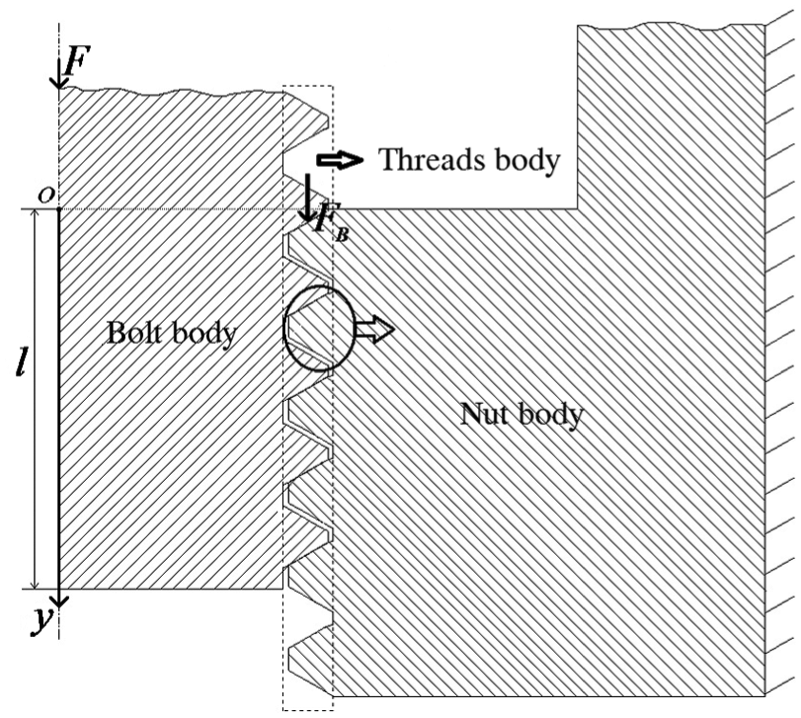
Force on threaded connections.
The elastic deflection of thread
According to the literature,
13
for the ISO metric triangle thread under unit force per unit width, the axial elastic deformation of thread includes the deflection
For the ISO thread under unit force at

The axial elastic deflections of unit length thread of nut are

where the sub-indices b and n represent the bolt and the nut. E is Young’s modulus,

Geometrical parameters of ISO thread.

Diagram of lead angle.
Therefore, for the thread on bolt and nut, the elastic deflection caused by unit force per unit width along axial direction is


For the threaded connections under compressive force F as shown in Figure 1, the axial deflection of the bolt and the nut can be expressed as

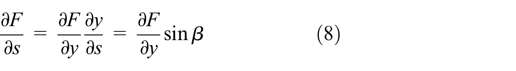
where s is the thread length along the direction of the helix, and

where y is the axial length of thread and
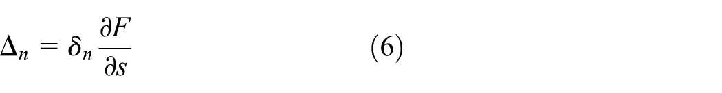
Substituting equation (8) into equations (5) and (6) leads to


where
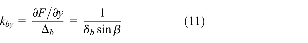
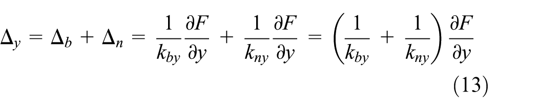
For the engaged bolt and nut, the axial deflection is
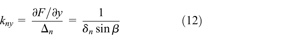
The stiffness of unit axial length is

Axial load distribution in threaded connections
Figure 1 shows the threaded connection structure including a fixed nut body and a bolt body. For the bolt body under compressive force F, the force will be transferred to the nut body through the threads. Because the structural deformation is presumed elastic, the bolt body, the nut body, and the thread body will exhibit deflection under force. However, the forces on the bolt body and the nut body differ from those on the thread body. Furthermore, their load distributions are also varied. Therefore, deformation modes of both the bolt body and the nut body will be different from those of the thread body. However, the bolt body and the nut body are joined by the thread body, their deformations should be compatible.
The region subjected to compressive force on the thread body ranges from

where
Similarly, strain

where
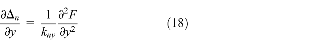
According to equations (9) and (10), the displacement gradients are respectively

In order to satisfy the deformation compatibility condition,

Substituting equations (15)–(18) into equation (19) leads to

where

By the boundary conditions
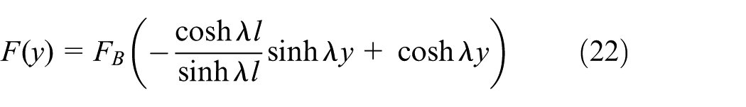
where
Total stiffness of threaded connections
According to the above deflections of the thread, the law of axial load distribution can be expressed as
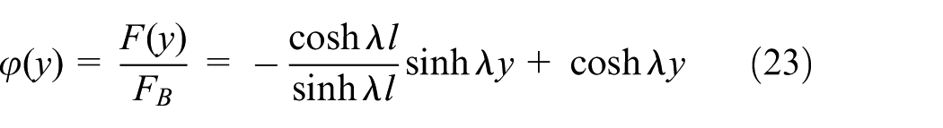
The deflection of thread should also satisfy the distribution law because the deflections are directly proportional to the loads. Therefore, axial deflection of the bolt and nut can be expressed as


where
Substituting equations (24) and (25) into equations (9) and (10) leads to

For the bolt, because the load is

where

Substituting equation (23) into equation (29), the thread stiffness of bolt can be expressed as

Similarly, the thread stiffness of nut can be expressed as

Because the meshing bolt and nut is in series manner, the total stiffness of engaged thread is

Finite element model
Finite element models are created to study the stiffness of threaded connections and the influence of material, pitch, and engaged length on the stiffness. The FEA method is used to calculate the bolt deflection in the axial direction, which is taken as the average nodal displacement

3D model mesh of standard bolted joint assembly (left) and bolt itself (right).
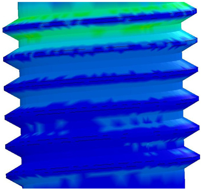
Contour plot of the screw stress.
Elastic material is used throughout this work. The bolt and nut materials used in this study are the same. Uniform pressure loading P is applied on the top surface of bolt. The stiffness of the thread connections

Tensile tests
In order to obtain the precise values of material parameter, we conducted the tensile tests for the standard tensile bar as shown in Figure 6. The universal test machine (UTM) is used to measure the load–deflection data of samples. The tested samples are made from steel, copper, and brass material, respectively.

Tensile tests for standard bar: (a) tensile test and (b) standard bar (unit: mm).
For the thread connection samples as shown in Figure 7, the test machine can only obtain the load f. Because the nut is fixed, the axial deflection of thread connection can be represented by the displacement variation
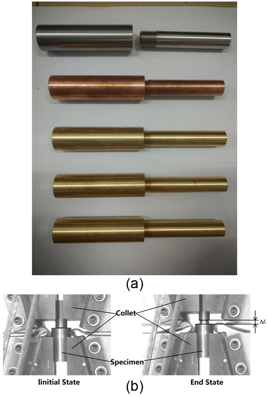
Tensile tests for thread connection samples: (a) thread connection samples and (b) tensile test.
Results and discussion
The stress–strain curves for tensile standard bar are shown in Figure 8. Figure 8(a) is the whole tensile curve, by which we not only can obtain the ultimate strength of material but also can calculate Young’s modulus. In order to distinguish clearly the elastic part of tensile curve, the partially enlarged curve for Figure 8(a) is shown in Figure 8(b). Therefore, the slope of the initial linear section in the curves is Young’s modulus.

Stress–strain curves for tensile standard bar: (a) the whole curves and (b) the partially enlarged curves.
By the same method, the ultimate strengths of thread connections are obtained. Table 1 presents the parameter of materials as well as the ultimate strength of material and thread connections. Comparing the ultimate strength, we can know that the values of thread connections are less than those of material. This reveals that the strength of thread connections is clearly lower than fixed connections.
Parameters of samples.

Table 2 lists the stiffness of thread connections from experiments, FEA, the current computational method, and Yamamoto method. From this table, it is very clear that the stiffness from this study is lower than Yamamoto method because we considered the load distribution along helix. Therefore, the stiffness from this study is in good agreement with the results from experiment and FEA.
Stiffness of thread connections

FEA: finite element analysis.
An alternative way to present and compare these results is executed in Figures 9–11. Figures 9–11 are the force-deflection curves for different materials, engaged lengths and pitches, respectively. In Figure 9, all the specimens 1#, 2#, and 3# have the pitch p 4 mm, the engaged length 20 mm, and the steel material, copper, and brass, respectively. All these curves indicate that the higher the Young’s modulus of material for thread connections, the higher the stiffness. But the ultimate strength of thread connections with brass is higher than copper due to the material properties.

Force–deflection curves for different materials: (a) the whole curves and (b) the partially enlarged curves.

Force–deflection curves for different engaged length: (a) the whole curves and (b) the partially enlarged curves.

Force–deflection curves for different pitches: (a) the whole curves and (b) the partially enlarged curves.
In Figure 10, material of all the specimens is brass. They have the same pitch, but the engaged lengths are 32, 20, and 12 mm. It is clear that the longer the engaged length for thread connections, the higher the stiffness and the ultimate strength. The reason for this behavior can be explained by equation (32). From this equation, we can know that the total stiffness obviously increases with the length of screw when the engaged length is small, and the value will not clearly change when the engaged length is large.
In Figure 11, the pitches of these specimens are 4, 3, and 2 mm. It states clearly that the stiffness of thread connections structure with the smallest pitch is the greatest, but the ultimate strength is the smallest. The reason for this behavior can be explained by equation (14). From the equation, the stiffness of screw increases with the decrease in lead angle. Because the lead angle is small for the screw with small pitch, the stiffness of screw with smaller pitch is higher. However, the component along the axial direction is small when the lead angle of screw is small. Therefore, the screw with smaller pitch has the higher ultimate strength.
Conclusion
A new computational method for threaded connection stiffness was developed in this study. Effects of some geometrical parameters of the engaged threads on the estimated stiffness were investigated for three different commonly used materials. The results can be summarized as follows:
The ultimate strength of threaded connections is lower than the corresponding material itself, which indicates that the strength of thread connections is obviously lower than fixed connection.
The computed threaded stiffness obtained in this study showed good agreements when compared with FEA results and experimental data. Results obtained using Yamamoto method were larger than those obtained using the present computational model, experiment, and FEA.
The stiffness was highly related to the material’s elastic properties, the engaged length, and pitch of thread. We could obtain higher stiffness through increasing Young’s modulus of the used material and the engaged length or by decreasing the pitch.
Footnotes
Academic Editor: Yangmin Li
Declaration of conflicting interests
The author(s) declared no potential conflicts of interest with respect to the research, authorship, and/or publication of this article.
Funding
The author(s) received no financial support for the research, authorship, and/or publication of this article.