
Abstract
The characteristics and working principles of the impinging by submerged water jet are analyzed, and the relevant mathematical model is optimized based on Rajaratnam’s theoretical and experimental study. A new mathematical model is constructed by adding an important parameter called impinging angle. A new experiment is designed according to the working conditions of various impinging distances and angles. In combination with the experiment data and with the use of the curve fitting method, the functional relationship between the impinging distance and angle as well as the coefficient C4 is obtained. The experiment results show that the scour depth decreases as impinging distance increases, followed by a trend from decline to rise before falling again; those two turning points occur within the range of 20d–25d. The scour depth constantly increases with rising impinging angle, and the maximum and minimum increasing ranges can reach 180% and 50%, respectively, with the impinging angle increasing from 40° to 90°.
Keywords
Introduction
Sedimentation is a considerable problem in rescue and salvage engineering, especially in deep sea. Thus, increasing attention has been paid to the removal of sediment on the wreckage. We use submerged water jet to remove seabed sediment to ensure the integrity of the wreckage. Sediment removal by submerged water jet is a complex physical process that involves several important rules of sediment erosion. Most studies currently deal with sediment erosion empirically, and many more attempts are made to understand the erosion process because of submerged water jet.
The study on submerged water jets was originally performed for sticky soil erosion problems. Fortier and Scobey 1 presented the concept of critical deposition velocity for riverbed sediment in their study on the canal situation in 1926. They identified that the faster the river flow velocity, the less the riverbed sediment. After that, more and more attempts are made to reveal the erosion process from different aspects. Considering the characteristic of the scour object, in 1930, Middleton 2 proposed that sediment scouring is not only related to flow velocity but also dependent on the physical properties of the sediment itself such as sand content rate and density through a series of contrast. In 1940, Rouse 3 proposed the method of simulating the process of natural erosion of sediment using water jets. He studied the effect of impinging by water jet and noted that the impinging velocity in a large experimental device is the main factor influencing the effect of scour; whereas in a small experimental device, the roughness of sand and other important physical properties should also be considered. In 2016, Taştan et al. 4 experimented with non-cohesive sediment and proved greater thickness of the non-cohesive sediment layer and depth of the jet scour hole under the same conditions of the jet.
One way to study the scour process is researching the type of jet and the variation in jet factors near the scour hole. Kobus et al. 5 compared submerged continuous and pulse jets in removing sediment, and the experiment shows that the increased pulse jet speed with the interplay of mud is better than that of leaving the continuous jet. In 1959, Dunn 6 analyzed the erosion process of plastic soil by vertical submerged water jet, prompting the concept of scour hole critical shear stress. To study the jet velocity, thickness, and shear force jet beam with the impact of the mud, Myers et al. 7 conducted a series of studies with comparative experimental and theoretical analyses. They noted that at the centerline of the jet, the speed increased continuously with distance decay.
With the continuous development of computer technology, several artificial intelligence models have been widely applied so as to simulate the scour process. Launder and Rodi 8 made an axisymmetric water jet and simplified it to a two-dimensional model. They studied the axisymmetric water jet in the generalized two-dimensional plane turbulence model and simplified water jet research questions to the jet velocity and pressure problems. Chinese scholars Qian et al. 9 used the Euler model to compare the simulation and the experimental analyses. They studied the characteristics of sediment removal by submerged water jet and noted that the deeper the sediment porosity, the higher the increase in scour depth.
After a long time of study, more and more scholars found that research of the scour hole plays an important role in revealing the scour process. Kuti and Yen 10 studied the effect of horizontal jet on scour sediment in the case of a constant flow rate, observed the changes in the shape of the scour hole over time, and identified that the mud effect is most evident at the beginning of time. In 2007, Mazurek and Hossain 11 proved that vertical gravity erosion is a leading key factor in forming scour hole under laboratory conditions containing 40% clay, 53% silt, and 7% of the sand jet cohesive sediment. Soltani-Gerdefaramarzi and colleagues12,13 investigated experimentally the effect of jet injection on the flow structure around a pier-scour hole in 2013 and 2014, respectively. The experiments were conducted with one jet, three jets and without jet injection under clear-water scour conditions. The results showed that the most optimal case in terms of pier-scour depth reduction occurred for lower flow depth, higher jet-flow rate, and angle between the jets equal to 90°. Moreover, the jets were able to reduce the scour depth, scour volume, and upstream slope of the scour hole up to 37.5%, 57%, and 25% for flow depth of 10.5 cm and 31.2%, 37%, and 57% for flow depth of 28 cm, respectively. By increasing the number of jets, turbulent kinetic energy increases, leading to a decrease in pier-scour depth. The results show that the jets alter the turbulent characteristics and vertical component of the velocity, causing a reduction in the strength of the down flow. The third-order correlations of velocity fluctuations show an obvious distinction for the jet injection experiments in comparison to that without injections, especially inside the scour hole. Rajaratnam, of the University of Alberta, presented the removal of sediment for turbulent jet in 1976 14 and 1977; 15 he adapted circular nozzle water jets to remove sediment in the experiments. In 1982, 16 he used submerged water jets in the experiment. He studied the jet velocity, jet impinging distance, sediment flow medium density ratio of sediment, and various factors that influence the case. In 1996, with the help of Aderibigbe, 17 he established a special submerged water jet bench and studied the morphological changes in sand bed by the vertical submerged water jet, and with the knowledge of statistics derived a function between the impinging distance and the scour hole depth.
In previous studies, sediment erosion plays an important indicator, and most are carried out in the vertical angle. What is more, most of the studies are applied in the area of hydraulic engineering. Currently, the study is only from macro trends, such that studying sediment removal yields no integrated relationship containing the impinging angle and distance. However, more stringent requirements are made to the complex work environment for impinging angle selection and forecasting scour depth in the area of salvage engineering. Considering the special environment of salvage engineering, previous sediment samples have been unable to meet the requirements of the experiments; thus, we choose a more tiny material as the experimental sediment. This study analyzes the sediment removal principle by submerged water jet at any angle and establishes a new scour depth mathematical model based on previous studies. With a new experimental device, a series of experiments are conducted and a new method for measuring the scour depth is proposed. We determined the coefficient C4 of the mathematical model of scour depth through a semi-empirical approach called curve fitting. After a series of validation works on coefficient C4, the experimental and theoretical data are compared to draw the conclusions that the scour depth of sediment removal increases as the impinging angle increases; the scour depth decreases at first and then increases before decreasing again. And the scour depth constantly increases with rising impinging angle. This study provides a strong reference for choosing the impinging distance and angle for the sediment removal by submerged water jet while carrying out the sediment removal project in salvage engineering.
Review
In 1939, Rajaratnam performed a theoretical study on the erosion of loose beds by submerged circular impinging vertical turbulent jets. The research on erosion by the jets was based on the contributions of the equation for the decay of centerline velocity of the jet and the equation for critical shear stress by Chiew 18 and Chee et al. 19 The function relationship was derived between the scour depth and the impinging distance. A definition sketch of the erosion of loose beds by submerged circular impinging vertical turbulent jets is shown in Figure 1.

Definition sketch.
As shown in Figure 1, εm is the maximum scour depth, U0 is the jet velocity at the nozzle, d is the jet diameter at the nozzle, h is the impinging distance, and D is the median size of the sand bed particles. The impinging distance h is a unique variable.
To determine the relationship between the maximum scour depth and the impinging distance, the following equations are combined:
The equation for modified Shields criterion;
The equation for critical shear stress and critical shear velocity;
The equation for the decay of the centerline velocity of the jet.
The modified Shields criterion can be expressed as equation (1), where C3 is an adjustable coefficient, which is found from Chiew’s experiments (1994) wherein K varies between 0.5 and 1.5

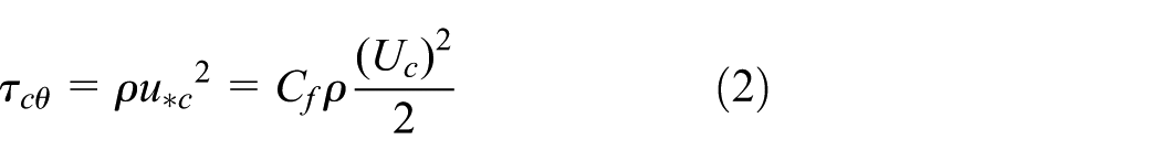
u*c is the critical shear velocity at any slope. The critical shear stress τcθ is given by equation (2), where Cf is the friction coefficient and Uc is the critical velocity for the incipient motion
Equation (3) expresses the decay of the centerline velocity Um of a submerged circular free jet with x, which is the distance along the jet centerline that is greater than the length of the potential core. Cj is the diffusion coefficient

Combined with the research of Chee and Yuen (2011), bed velocity Ub is computed by replacing Cj with an experimentally determined coefficient Cjb. Equation (3) is rewritten as equation (4)

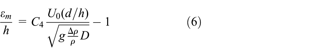
The expression for the maximum scour depth is obtained when Ub is equal to Uc, x is equal to (εm + h), and equations (1), (2), and (4) are combined. The final expression is given in equation (5). The coefficients are combined to form another adjustable coefficient C4 as shown in equation (6)

Present theoretical research
Different from Rajaratnam’s research, the object of our sediment removal is fine clay under the deep sea. There are so many differences between the sand used by Rajaratnam and fine clay in the physical properties, so his mathematical model is not suitable for our study. What is more, we should not only study the characteristics and working principles of the impinging by submerged water jet. In view of the differences between Rajaratnam’s research and the present research, we come to the following mathematical model. Jet angle θ is brought in based on Rajaratnam’s theoretical research. A submerged water jet at any angle is shown in Figure 2.
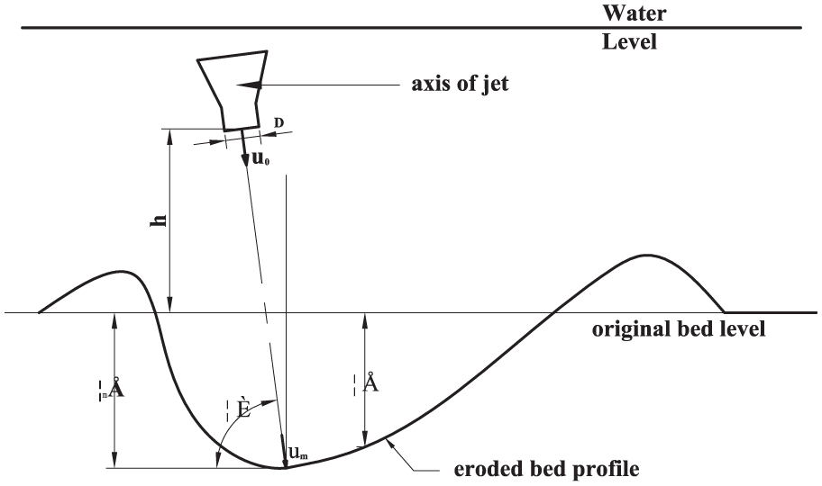
Definition sketch of sediment removal by submerged water jet at any impinging angles.
The main principle in the use of a submerged water jet to flush sediment is that the jet generated by boundary shear stress is greater than that of the shear strength of the cohesive sediment. Thus, the momentum exchange is caused between the sediment and the surrounding environment. When the sediment and jet are at the same speed, the sediments gradually spread to the surrounding environment with the jet and form the hole.
By referencing the derivation process of Rajaratnam, the three equations above, i, ii, and iii, are obtained. The jet angle difference does not affect equations (1) and (3); thus, it will lead to the changes in equations (2) and (3). According to the trigonometric function relationship, formula (2) is replaced by equation (7), whereas equation (4) is replaced by equation (8)


Equation (9) is obtained by combining equations (1), (7), and (8)

Based on the research results of Rajaratnam, equation (10) is derived

In simplifying the function relationship, the coefficients are combined to form another adjustable coefficient C4 as shown in equation (11)

Laboratory experiments
As shown in Figures 3 and 4, the experiment device consists of an experimental water tank, a nozzle clamping device, a centrifugal pump, and a bucket. The experimental water tank is 1 m long, 1 m wide, and 0.8 m high. Two liner guides on both sides of the water tank are used to control the dolly moves of the nozzle. The model of the centrifugal pump is JET750 with a power of 0.75 kW, a hydraulic head of 45 m, and a maximum flow of 3.5 m3/h.
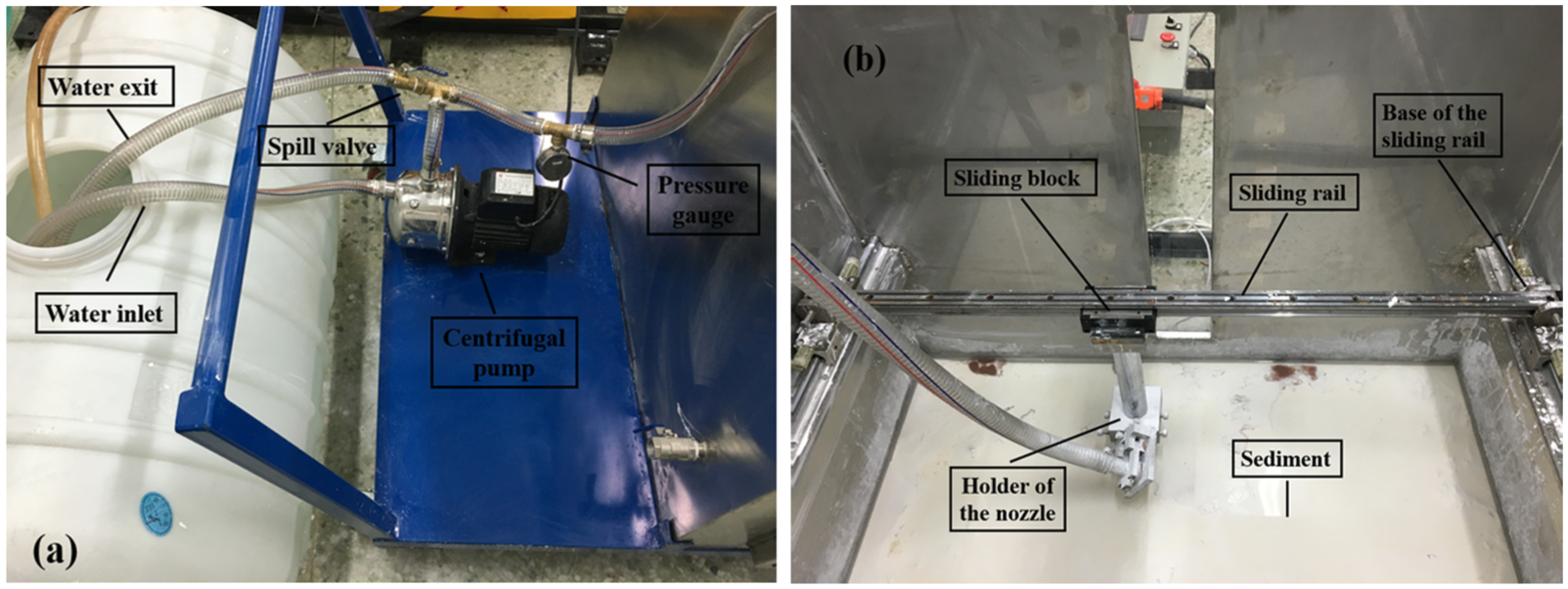
Physical diagram of the experimental device for sediment removal by submerged water jet: (a) piping layout and (b) nozzle arrangement.

Defining sketch of the device.
Experimental contents
To study the effect of various impinging angles and distances under submerge condition, we performed a total of 88 groups of experiments using 50 µm silica powder as experimental sediment. In each experiment, the inlet pressure of the nozzle P0 is 0.1 MPa, the nozzle diameter d is 3 mm, the outlet velocity is U0, and the average particle diameter of the sediment is D. The impinging distance h includes the eight values of 10d, 12d, 15d, 18d, 20d, 22d, 25d, and 28d, and the impinging angle θ includes the 11 values of 90°, 85°, 80°, 75°, 70°, 65°, 60°, 55°, 50°, 45° and 40°.
Each experimental process consisted of preparing thin steel plate with the same size of A4 paper ahead of time and using double-side glue to stick a red A4 paper to a thin steel plate. Afterward, the setup for the jet is mounted, and the impinging distance and angle are adjusted. The tank was then fed with water to construct a submerged environment. After persistently supplying water to the nozzle by starting the centrifugal pump for 5 min, the drainage is soon opened. The maximum depth of the scour hole is cut along the central axis to keep half of the hole after accomplishing a constant head. Afterward, a steel plate with red A4 paper is attached to half of the scour hole section tightly (Figure 5). Next, a trowel is used to remove the sand in the other half of the scour and a drying process is conducted for the steel plate and sediment using a drying machine along the scour hole. After 5 min, the steel plate with red A4 paper is removed to measure the maximum scour depth for five times. Finally, the maximum scour depth is the maximum of the five measured values. As shown in Figure 6, we can sprinkle a little sticky small sand with various colors such as 800 µm garnet to make the half section of the crater clearer after each test.
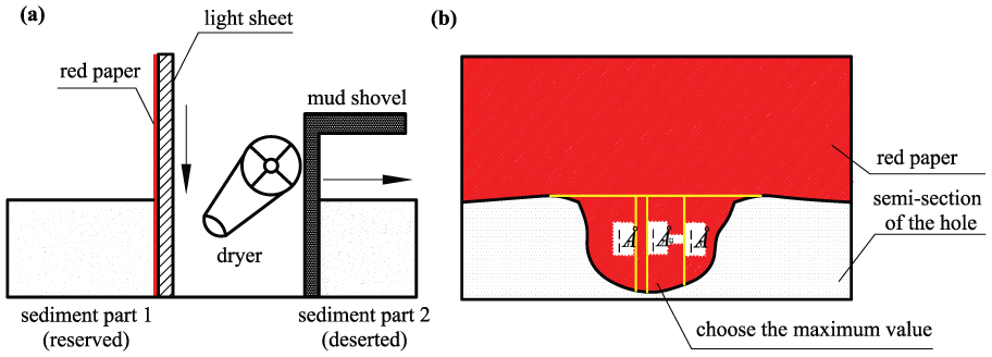
Schematic diagram of the measurement method of the maximum depth of scour hole: (a) schematic diagram of measurement method of semi-section outline drawing of the scour hole and (b) schematic diagram of the option method of the maximum depth of scour hole.

Physical map of scour depth measurement: (a) vertical view of the scour hole, (b) half-sectional view of the cut scour hole along the axis, and (c) semi-section outline drawing of the scour hole on the plate.
Results and analysis
Given the complex environmental factors and jet conditions of sediment removal by submerged water jet, the results of the combined results of the theoretical studies and experimental validation are generally required to solve the influence coefficient in the mathematical model. Table 1 shows the experimental data, wherein the row title is the impinging angle, the column title is the impinging distance (a multiple of the diameter of the nozzle), and the data are the scour depth (mm).
Experimental data of the scour depth with various impinging distances and impinging angles.

Equation (11) indicates that εm/h changes with Ec sin 2θ. Based on the curve fit of the data obtained from the experiments using MATLAB software which uses the method of evolutionary polynomial regression (EPR), the fitting curve is shown in Figure 7 and the coalescent degree of the curves can reach 94.1%. Thus, equation (11) can be optimized as equation (12)
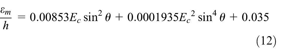

Relationship curve between the maximum scour depth variation in sediment removal and Ec sin 2θ.
Based on Figure 7, we found that the variation in the maximum scour depth generally grows with increased Ec sin 2θ. However, the changed trend of the experimental data remained broadly consistent with the fitting curve. With the experimental conditions constantly changing, the value of Ec sin 2θ changes around the range of 5–55, the linear error of the variation in scour depth, and Ec sin 2θ is 9.07%.
In testing the applicability of the mathematical model, we only changed the impinging distance under the premise of maintaining experimental conditions and conducted 22 groups of experiments. In each experiment, the nozzle inlet pressure P0 is 0.1 MPa, the nozzle diameter d is 3 mm, the outlet velocity is U0, the average particle diameter of the sediment is D, the impinging distance h includes 30d and 35d, whereas the impinging angle θ still includes the 11 angles of 90°, 85°, 80°, 75°, 70°, 65°, 60°, 55°, 50°, 45°, and 40°. Comparing the experimental data and mathematical model (Figure 8), the experimental data are consistent with the result of the mathematical model and the maximum error is 4 mm, thereby showing that equation (12) has universal applicability.

Comparison of the theoretical and experimental data of scour depth with the impinging distances of 30d and 35d.
Impinging distance influence on scour depth
Impinging distance plays an important role in the sediment removal process by submerged water jet. Therefore, studying the influence of impinging distance on the submerged water jet has an important guiding role for the development of the field. Figure 7 shows the change regulation of the theoretical and experimental values of the maximum depth of submerged water jet changing over the standoff under the four various impinging angles of 80°, 70°, 60°, and 50°.
Figure 9 shows the scour hole curve calculated from the mathematical model or the experimental curve; the curve trend is the same. Therefore, the scour hole depth of the sediment removal by submerged water jet decreases as the impinging distance increases and then increases to a critical point before decreasing with the increasing impinging distance.

Regulation of the scour depth of the sediment removal by submerged water jet with varying impinging distances.
According to the various effects of jet-flow shearing force, resistance, and horizontal velocity in the sediment removal process, we divide the increasing impinging distance into three patterns and two critical points. Pattern 1 is shown in Figure 10(a). As a result of relatively minimal impinging distance, jet bundle is intensive and the sediment vertical shear force caused by the jets is far greater than the water resistance of the water environment. Thus, the sediment rapidly completes the transport process of leaving the scour hole along with the jet reflection. Currently, scour hole depth is mainly determined by the resultant action of jet-flow shearing force and water resistance. In this pattern, with the increasing impinging distance, the sediment vertical shear force caused by the jets decreases gradually, whereas the water resistance is constantly increasing. Therefore, under the effect of one fall, another rises between the jet-flow shearing force and water resistance; thus, the jet scour depth follows a decreasing trend.

Three various scour patterns corresponding to various impinging distances: (a) a small impinging distance, (b) a moderate impinging distance, and (c) a large impinging distance.
With increasing impinging distance, the jet-flow shearing force is constantly decreasing as the resistance is increasing gradually; the action of the sediment leaving from the scour no longer depends on the transport function of the vertical reflection flow. Currently, jet bundle gradually diffuses to the horizontal direction. When the horizontal transport effect of horizontal velocity is greater than the effect of sediment, leaving the scour in the vertical direction by relying on reflected flux changes the main factors affecting the scour hole depth into the horizontal transport effect of the sediment. Therefore, the sediment removal process reaches a critical point. The increasing effect of jet bundle divergence, the resultant force of jet-flow shearing force, and water resistance can cut the sediment forming an in-depth scour hole.
However, in pattern 2, the effect of the sediment leaving the scour hole along with the water flow is continuously becoming strong, and the residual sediment in the scour hole is continuously reduced; furthermore, the scour depth gradually increases (Figure 10(b)). Increasing the impinging distance, the action of jet-flow shearing force is smaller, and the jet can no longer cut the sediment at a certain moment to generate a large depth of scour hole. Hence, the initial depth of the scour hole is significantly reduced even if the horizontal direction of the sediment transport is good. In pattern 3, an in-depth scour hole is produced; thus, the sediment removal process reaches another critical point. With the rapid decline of the jet-flow shearing force and the gradual increase of water resistance, the initial scour depth generated by the jet will constantly reduce even at a relatively good level of sediment transport environment, and the scour gradually decreases, that is, pattern 3, which is shown in (Figure 10(c)).
Impinging angle influence on scour depth
In the application of salvage engineering, choosing a suitable jet angle is vital for the salvage site cleaning efficiency and the sediment removal effect. We should not only guarantee a certain depth of sediment removal but also consider the remotely operated vehicle (ROV). Thus, it is necessary to analyze the influence of impinging angle and scour depth. In the case of deep water, the sediment removal process relies on the ROV’s manipulator clamping sediment removal operation tool, while ROV needs to keep a certain distance with the sea floor when cleaning up the site. Therefore, to ensure the sediment removal’s effect and security, we ignore the study of jet angle below 40° and only consider the jet angle within the range of 40°–90°. As shown in Figure 11, the scour depth of the submerged water jet increases with an increase in the impinging angle. By analyzing the changing trend of the test and theoretical curves, it is found that when the impinging angle is smaller, with the increase in the jet angle, the depth of the scour hole evolves rapidly. However, when the impinging angle is larger, the depth of the scour hole is relatively slow as the impinging angle increases.

Regulation of the submerged water jet scour depth changing over impinging angle.
Conclusion
Combining the results of previous research, this article studies the working characteristics and principles of the submerged water jet sediment removal. Based on Rajaratnam’s theoretical and experimental study on sediment removal by vertical submerged water jet, the change in the characteristics of sediment removal by submerged water jet under various impinging angles is proposed. By establishing a new experimental device, which meets the experimental requirements of sediment removal at various impinging angles and distances, a total of 110 groups of experiments are performed. Based on research contents of Rajaratnam on mathematical model derivation of scour hole depth by joining a new factor influencing the impinging angle, this study established a new mathematical model of scour hole depth. Combining the experimental data, it provides the variation curve of the mathematical model of scour hole depth and deduces the function relationship between the parameters of the depth function expression of the scour hole, and the impinging angle and distance. The fitting degree of the mathematical model of the scour depth reached 94.1%. By extracting the experimental data, the influence of the impinging distance and angle on the scour depth is separately analyzed as follows:
With increased impinging distance, the scour depth decreases, followed by an increasing trend, before gradually decreasing after reaching a certain value. Those two turning points occur within the range of 20d–25d, and thus, we should pay more attention to this angle range in the practical engineering application; we call this angle range “sensitive angle.” On the whole, the scour depth decreases nearly 33.3% with the impinging distance increasing from 10d to 35d.
The scour depth constantly increases with rising impinging angle. This finding shows that when the impinging angle is smaller and the jet angle is increasing, the depth of the scour hole changes rapidly. However, when the impinging angle enlarges, the depth of the scour hole is relatively as slow as the impinging angle increases. Overall, the maximum and minimum increasing ranges can reach 180% and 50%, respectively, with the impinging angle increasing from 40° to 90°.
Footnotes
Appendix 1
Academic Editor: Ming-Jyh Chern
Declaration of conflicting interests
The author(s) declared no potential conflicts of interest with respect to the research, authorship, and/or publication of this article.
Funding
The author(s) disclosed receipt of the following financial support for the research, authorship, and/or publication of this article: This work was financially supported by the National Natural Science Foundation of China (grant nos 51275063, 51405054, 51475064), the Fundamental Research Funds for the Central Universities (no. 3132016067), the Liaoning Natural Science Foundation (no. 2014025007), the National Key Technology Support Program (no. 2014BAB12B00), the MOT Science and Technology Project (no. 2014328204050), the Dalian science and technology planning project (2014A11GX023).