
Abstract
Using the largest semi-autogenous grinding mill in China as a model, collision energy was analyzed on the basis of the multi-layer kinematics of the steel balls. First, the kinematic equation of the steel balls was obtained by considering the multi-layer characteristics of the steel balls. Second, the collision energy of the inner-layer steel balls was addressed according to its kinematic characteristics. Finally, the total collision energy per unit time was obtained. Results show that the leaving angle decreases as the mill speed ratio increases and as the radius ratio increases, but the leaving velocity increases linearly. Moreover, a discontinuity point of the tangential collision velocity occurs at an angle factor β = 0, and the angle factor β is divided into two intervals: [−3, 0] and [0, 1.5]. The leaving angles corresponding to a tangential velocity equal to zero are calculated to be 1.185 and 0.7854 rad in the two intervals. In addition, the sum collision velocity increases when β is less than zero, but it decreases sharply above zero. The maximum total collision energy per unit time occurs at 84.2% of the mill speed corresponding to the optimal mill speed ratio.
Introduction
A semi-autogenous grinding (SAG) mill is dependent on rotation to carry the grinding media around the mill for minerals impact and attrition, as presented in Figure 1. It is an energy-intensive unit operation and requires extremely wasteful equipment in terms of energy utilization and consumption. Considering SAG mill environment itself, it can be abstracted to be a type of equipment that produces a collision energy spectrum. 1 The input energy from the power system is dissipated by the motor loss and mechanical loss by consuming 5%–10% and 10%–15% of the input energy, respectively. Moreover, no more than 3%–8% of the supply energy is utilized for breaking minerals, 2 while the rest of the collision energy is dissipated indirectly in the form of heat. Both “Industry Energy-Saving in the 12th Five-Year Program of China” and “Building Materials Industry in the Twelfth Five-Year Guideline” have proposed that it is necessary to develop a large-scale mill and generalize the energy-saving emission technology.3,4

Sketch of SAG.
During the grinding process, the grinding media is considered to be the input energy medium, and the deciding factor in final collision effectiveness is determined by the kinematic characteristics of the grinding media. The kinematic characteristics of the grinding media are affected by the grinding media system, operating conditions, and mill configuration, while the ratio of the mill speed and the filling rate are the major factors. 5 Classic theory presumes that the grinding media is distributed in layers, 6 and the total collision energy is assumed to be the accumulation of the collision energy of the grinding media in each layer. Currently, the largest SAG mill in China has a diameter of 10.37 m and a length of 5.19 m and was designed by CITIC Heavy Industries. 7 This mill was used by Jiangxi Copper Corporation, as shown in Figure 2. The grinding media has identical diameters of 125 mm, and the filling rate of the grinding media is 12%. In the cataracting process of the steel balls, the collision energy carried by a single steel ball is enormous and is critical for SAG mill performance. 8 For instance, the impact force generated by a 76-mm steel ball within a 2.74-m mill equals 2850 MPa. 9 The yield strength of the liner designed by CITIC Heavy Industries equals to 1000 MPa, and the impact force of a steel ball dropping from a height of 12 m can reach 4100 MPa. 10 Based on the kinematics of the steel balls, the collision energy carried by the outer layer mainly depends on the mill speed ratio; however, the collision energy carried by the inner layers is dependent not only on the mill speed ratio but also on the inner layers’ radii. Thus, it is necessary to address the effect of the mill speed ratio and the radius ratio on the collision energy. In addition, because of the relative tangential velocity between the mill and the steel balls, the total collision energy calculated using the classic theory should consider the relative tangential velocity.11,12

Photo of the largest SAG mill (10.37 m × 5.19 m).
Currently, the kinematic characteristics of steel ball have been numerically simulated using discrete element methods13–19 and experimentally investigated through sensor technology.20–27 It was found that the operating parameters had a profound effect on the charge characteristics, 28 and the effect of operating variables on the optimum performance of the mill still needed to be addressed to enhance energy utilization. Rajamani et al. 29 considered that the collision energy could be changed through the choice of operating parameters, and the collision frequency of the steel balls was considered as a function of the collision energy. Liu et al. 30 considered that the motion of single steel ball was divided into two stages, and the corresponding motion mechanism in each stage was addressed using a theoretical method. Zhang studied the change in the normal accumulation factor with mill speed on the basis of Davis’ multi-layer motion model. The steel balls were considered to be an en masse layer, and it was found that the desired mill speed was closely related to the maximum normal accumulation factor, but the relative mill speed was not taken into consideration. 31 Based on the kinematic characteristics of the steel balls, the collision energy was restudied and recalculated while taking the relative tangential velocity into account. Liu 32 proposed a new method to optimize mill speed according to the relative tangential velocity, and the accumulation value of the kinetic energy factor in each layer was selected as the objective function for determining the maximum mill speed. Additionally, a trajectory envelope method was employed to determine the optimized radius ratio and leaving angle of the steel balls. Nevertheless, the direction of relative velocity was assumed to be fixed. 33 Wan and Hu used a non-linear optimization method that focused on optimizing the point of maximum collision energy, the maximum potential collision energy, and the total collision energy per unit time. In this work, it was noted that the maximum total potential energy occurred at the speed ratio equal to 84.57%.1,12 However, neither the kinematic parameters nor the radius ratio were studied. Yin et al. 34 studied the kinematic properties of a large-scale mill considering the multi-layer effect, but the collision energy and desired mill speed were not determined. Lu et al. 35 studied the optimal mill speed ratio corresponding to the maximum collision energy per unit time, and then, the optimal mill speed for impact and attrition grinding was determined by the grinding performance factor. There is no unified or standard approach to determine the optimized mill speed. To achieve the desired mill speed for a large-scale mill, investigators have employed scaled-down versions or have used custom-size mills to address how mill performance is affected by the mill speed, but the shortcomings of unrealistic simplifications and assumptions were also clear. 36 For a large-scale ball mill, the collision energy carried by a single grinding media was tremendous, as well as the difference of in the collision energy of each layer was tremendous. Despite the fact that the collision energy of a ball mill has been extensively studied, few papers in the literature address the collision energy of a large-scale mill for optimizing mill speed. Additionally, the relative mill speed between the steel balls and the mill shell cannot be neglected in optimizing large-scale mills.
In this study, the kinematic properties of the steel balls are thoroughly studied. Taking into account the kinematics of the multi-layer steel balls, a modified kinematics equation is developed to address the kinematics characteristics and collision energy for the largest SAG mill in China. Finally, the optimized mill speed is obtained, which should supply basic data support for the design of optimized mills.
Multi-layer kinematic characteristics of grinding media
Figure 3 depicts the motion schematic representation of the steel balls in various layers. Steel ball cataracting occurs at point Ak with leaving velocity v_k and leaving angle αk. The subscript symbol k indicates that the steel ball is located in layer k with an effective radius Rk. The subscript symbol n indicates the limitation layer at which cataracting occurs. The A and B symbols demonstrate the leaving point and landing point, respectively. The trajectory of the steel ball follows a parabolic equation with the landing angle βk.

Motion schematic representation of grinding media in various layers.
To quantitatively address the kinematic characteristics of the steel balls, the multi-layer motion model of Morris is adopted. Based on the coordinate and velocity equations of Rose’s model, the kinematic parameters are obtained, including parameters such as the leaving velocity, leaving angle, impact velocity, and the coordinate of key point. During the cataracting process of the steel balls in each layer, the motion of steel ball is assumed to be continuous and multi-layered, and no layer interferes with another. By converting the xA0y coordinate system to the XOY coordinate system, the parabolic equation of a steel ball in layer k is obtained as follows

where Xk and Yk are the abscissa and ordinate, separately, αk is the leaving angle in layer k; Rk is the effective radius in layer k; g is gravitational acceleration; and v_k is the leaving velocity in layer k.
In steel ball cataracting, the leaving velocity and angle are distinctly different in each layer. The leaving angle of the outer layer depends only on the mill speed ratio, while the leaving angle of the inner layer depends not only on the mill speed ratio but also on the radii of the inner layers. The equations for the leaving angle and leaving velocity are given as follows


where ψ is the mill speed ratio, ξk is the radius ratio, that is, the ratio of the effective radius of layer k, and the effective radius of outer layer, ξk = Rk/R0.
Substituting equations (2) and (3) into equation (1) and rearranging equation (1) as follows

Taking the derivative of equation (4) at the point of Bk, the collision velocity of layer k is obtained. Substituting equations (2) and (3) into it and rearranging
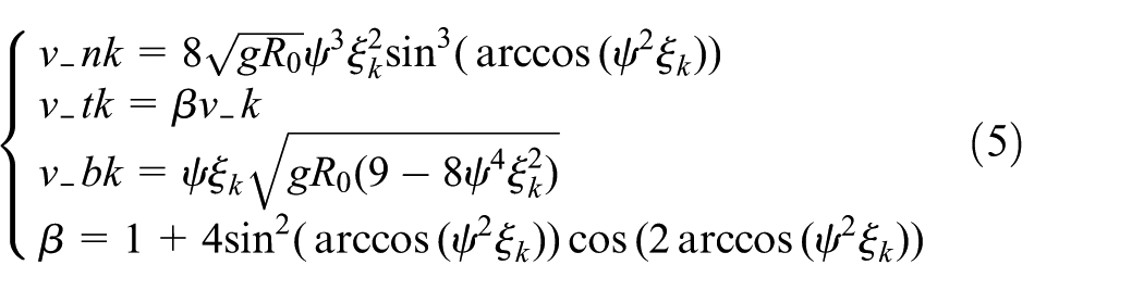
where v_nk is the normal collision velocity at point Bk, β is the angle factor, which depends on the leaving angle, v_tk is the tangential collision velocity at point Bk, and v_bk is the sum velocity at point Bk. From equation (5), the tangential velocity is divided into two stages when β = 0 that increase or decrease by ψξk(gR0)1/2, as shown in Wan et al. 1

where β1 and β2 are the angle factors related to the mill speed ratio and radius ratio, and the symbols 1 and 2 represent the intervals of β > 0 and β < 0, respectively.
Collision energy of grinding media
As the mill turns one complete circle, the steel balls impact the liner several times. Therefore, the impact frequency of the steel balls is given as follows 12

where nc is the critical speed of mill, and rb is the radius of a steel ball

where i represents layer k, and kn is the limitation radius ratio, which is calculated from the mill filling rate, kn = 0.5. Hence, the ratio of radius is obtained as Table 1. As can be seen in Table 1, the radius from the outer layer to the inner layer decreases. The outermost layer has a radius of 5.0325 m and a radius ratio of 1.0, whereas the innermost layer has a radius of 2.5163 m and a radius ratio of 0.5.
Radius ratio parameters.

Combining equations (5), (6), and (7), the total collision energy per unit time is obtained as follows

where ρb is the density of a steel ball.
The total collision energy is divided into the collision energy of the tangential component and the normal component. Combining equations (5), (6), and (7), the collision energy of the tangential component and the normal component is obtained as follows

Rewriting equation (10), equation (11) is obtained as follows

where C is constant, and Σε is the sum accumulation factor, the subscripts 1 and 2 represent β > 0 and β < 0, respectively, and Σεn and Σεt are the normal and tangential accumulation factors, respectively. 31 Thus, the expression is given as follows

From equations (9) and (10), the collision energy of the normal component is mainly used for impact grinding, while the collision energy of the tangential component is primarily used for attrition grinding. Hence, the proportions of normal collision energy and tangential collision energy on total collision energy are given as follows

Results and discussion
Kinematic analysis of steel balls
Based on equation (2), the leaving angle is the function of the mill speed ratio and radius ratio, as shown in Figure 4. As Figure 4(a) demonstrates, the leaving angle αk decreases with an increase in the mill speed ratio. The curve of αk of the outer layer decreases sharply, while that of the inner layer decreases gradually. Considering the large-scale SAG mill (Φ10.37 m × 5.19 m), the minimum radius ratio was calculated to be approximately equal to 0.5 in terms of filling rate limitation. Because of the relative tangential velocity of the mill and steel balls, the leaving angle is calculated to be equal to 1.185 and 0.7854 rad, separately, only if the tangential velocity equals zero in the intervals of β < 0 and β > 0. When β = 0, the leaving angle is calculated to be equal to 0.9728 rad. When the mill speed ratio reaches 100%, the centrifugal motion of the outer layer occurs, while the steel balls in the inner layer are still cataracting. This effect occurs mainly because the required centrifugal critical speed of the outer layer is less than that of the inner layer. Hence, the underlying principle of the centrifugal motion of the outer layer will not occur, and it is necessary to ensure that the motion of the inner layer is cascading or cataracting to increase the useful work for further impact grinding and attrition grinding. In addition, the contour line of αk is presented in Figure 4(b). This figure shows that if the mill speed ratio is less than 40%, the effect of the radius ratio on the leaving angle can be neglected. As the mill speed increases, the difference in the leaving angle of each layer becomes evident. Hence, the leaving angle can be obtained directly based on the coordinates (ξk, ψ).
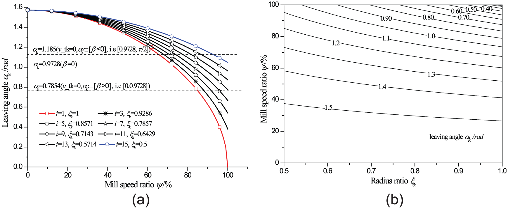
The effect of mill speed ratio and radius ratio on leaving angle: (a) the trends of αk and (b) the contour lines of αk.
After the steel balls of each layer approach the leaving angle, they will be projected along a parabolic trajectory, as in equation (4). The effect of the mill speed ratio and radius ratio on the leaving velocity is depicted in Figure 5. According to Figure 5(a), the leaving velocity increases linearly with the mill speed ratio with a slope ξk(gR0)0.5. The maximum leaving velocity of the outer layer equals 7.023 m/s, which is approximately 2.5 times that of the inner layer. Combining Figures 4(a) and 5(a), it is found that the larger is the leaving angle, the smaller is the corresponding leaving velocity. Figure 5(b) illustrates the contour lines of leaving velocity. As can be seen, the contour line distribution of v_k is more uniform than that of the leaving angle, and the leaving velocity of each layer is approximately the same at the mill speed ratio below 20%. Due to the difference in the tangential velocity between the mill and the steel balls, the collision velocity of the steel balls changes, but it has no influence on the leaving velocity.

The effect of mill speed ratio and radius ratio on leaving velocity: (a) the trends of v_k and (b) the contour lines of v_k.
The effect of the mill speed ratio on the tangential velocity is presented in Figure 6. The effect of the leaving angle on the angle factor β is analyzed. If the angle factor equals zero, that is, the impact velocity of the tangential component equals zero, the steel balls will vertically impact the liner or steel balls at a leaving angle equal to 0.9728 rad. In the grinding process, the collisions are divided into two types: central impact and an oblique impact. During the process of oblique impact, the tangential velocity is divided into two parts at the turning point of a leaving angle of 0.9728 rad. The tangential velocity will decrease by v_k at a leaving angle less than 0.9728 rad; conversely, it will increase by v_k at a leaving angle greater than 0.9728 rad. For instance, the radius ratio of 0.8571 is selected for analyzing the tangential velocity. Considering the relative tangential velocity, the curve has a discontinuity at 81% of the mill speed. The tangential velocity increases by 4.85 m/s in the interval of [−3, 0] and decreases by 4.85 m/s in the interval of [0, 1.5]. Because of the difference in tangential velocity in the interval of [−3, 0] and [0, 1.5], the tangential velocity in the interval of [−3, 0] is addressed in Figure 7. Below a constant mill speed ratio in each layer, the tangential velocity decreases, while above it, increases and reaches the discontinuity point of each layer.

The effect of mill speed ratio on tangential velocity: (a) angle factor β and (b) tangential velocity at ξk = 0.8571.
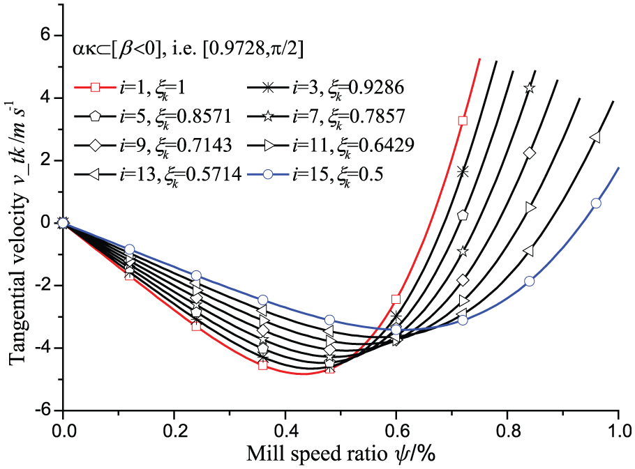
The effect of mill speed ratio on tangential velocity in the interval of [0.9728, π/2].
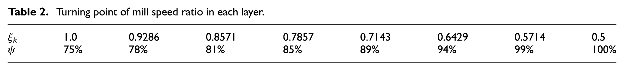
During the grinding process, the normal collision velocity is the main source for impact grinding, while the tangential collision velocity is the main source for attrition grinding. The normal collision velocity and sum velocity are presented in Figure 8. Figure 8(a) illustrates the trend of mill speed ratio on normal collision velocity. Below αk of 0.9728 rad, the normal collision velocity increases, while above 0.9728 rad, the normal collision velocity decreases. The corresponding mill speed ratio gradually shifts right with decreasing radius ratio, and the turning point is calculated in Table 2. Taking the tangential collision velocity into account, the sum velocity is obtained, as shown in Figure 8(b). In Figure 8(b), the trend of the sum velocity is similar to that of the normal collision velocity. However, the velocity has a discontinuity point at αk of 0.9728 rad, so the velocity must have a maximum value at 0.9728 rad.

The effect of mill speed ratio on normal collision velocity and sum velocity: (a) normal collision velocity and (b) sum velocity.
Turning point of mill speed ratio in each layer.
As seen in Figure 8, the velocity must have a maximum value at the turning point, and the maximum value of the normal collision velocity and the sum velocity is illustrated in Figure 9. The figure shows that the maximum value decreases as the mill speed ratio increases, and mathematical equations are obtained by linear regression to fit the data points. For the maximum value of the normal impact velocity, the equation is expressed as −13.78ψ + 23.64 with a correlation coefficient of 0.994. For the maximum value of the sum velocity, the equation is expressed as −15.1ψ + 25.65 with a correlation coefficient of 0.992.
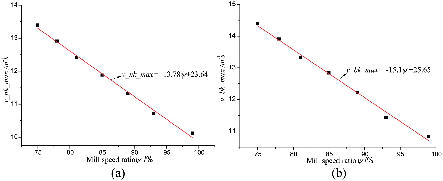
Maximum values of normal collision velocity and sum velocity: (a) normal direction and (b) resultant direction.
Collision energy
Based on the kinematic characteristics of the steel balls, the collision energy per unit time is addressed, and the maximum collision energy of the steel ball occurs in the outer layer with a leaving angle equal to 0.9728 rad. The collision energy and energy ratio of the outer layer are presented in Figure 10. Figure 10(a) indicates that the maximum collision energy equals 832 J. This value occurs at ψ = 75% and is slightly higher than that of the normal collision energy, while it is far above that of the tangential collision energy. As seen in Figure 10(b), the trend in energy ratio is similar to the hump, and the energy ratio has a discontinuity at ψ = 75% corresponding to the maximum collision energy, which is 13.22% higher than that of the normal collision energy and 86.67% higher than that of the tangential collision energy.

The collision energy and the energy ratio of the outer layer: (a) collision energy of the outer layer and (b) energy ratio of the outer layer.
The total collision energy is the sum of the collision energy in each layer, and the maximum collision energy E_b1 in the outer layer is not the same as that of the maximum total collision energy. The accumulation factor and the ratios of normal and tangential energy to total energy are presented in Figure 11. As Figure 11(a) illustrates, below ψ = 84.2%, the accumulation factors Σε and Σεn increase, and above it, they decrease rapidly. The result agrees with the optimal 84.57% of mill speed. 12 The observation indicates that the optimal mill speed is irrelevant to the mill configuration. If the mill speed ratio is greater than 84.2%, the maximum collision energy and difference in collision energy of each layer decrease indicating that the wear of the steel balls and the liner will lead to homogeneity. Maximum Σε and Σεn are 12.37 and 11.83, respectively, while the maximum Σεt is 0.77. As seen in Figure 11(b), the ratio of the normal component to the total energy increases as the mill speed ratio increases, while above ψ = 75%, it is unchanged and is maintained at 0.98, which is far more than the ratio of the tangential component to the total energy. Therefore, to increase the normal collision energy when impacting minerals, the mill speed ratio should be kept in the range of 75%–84.2%, which will have the largest utilization of energy.

Accumulation factor and ratio of normal/tangential energy to total energy: (a) accumulation factor and (b) ratio of normal/tangential energy to total energy.
Conclusion
To address the desired mill speed of the large-scale SAG mill (ϕ10.37 m × 5.19 m) in the pre-design stage, a modified mathematical formulation is developed. The kinematic and collision properties are addressed on the basis of a mathematical formulation. According to the mathematical formulation, the mill speed can be optimized in the design stage of a large-scale SAG mill, potentially saving a great deal of time without increasing the amount of capital costs. The main results are obtained as follows:
From the outermost layer to the innermost layer, the cosine function of the leaving angle increases linearly with increasing radius ratio and the square root of the mill speed. The leaving velocity increases linearly with increasing mill speed, and the slope equals ξk(gR0)0.5.
The relative collision velocity in the tangential direction should either subtract the leaving velocity from or add to the tangential velocity in the interval of [0, 1.5] and [−3, 0], respectively. The turning point appears at the leaving angle of 0.9728 rad for each layer, resulting in the maximum velocity. The turning point corresponding to the mill speed increases from the outer layer to inner layer. The resultant velocity initially increases as the mill speed increases and then decreases. The maximum velocities in the normal and resultant directions are fitted by the linear regression method and are expressed as −13.78ψ + 23.64 and −15.1ψ + 25.65, respectively. Hence, the collision velocity can be determined by changing the mill speed and layers of steel balls giving helpful information about addressing the high-impact resistant properties of the liner to develop high-performance liners.
The normal and total accumulation factors increase first and then decrease with increasing mill speed, whereas the tangential accumulation factor fluctuates in a narrow range. The maximum normal and total accumulation factors equal to 12.37 and 11.83, respectively, corresponding to the desired mill speed of 84.2%. Therefore, the energy characteristic analysis provides a quick and accurate method for optimizing the mill speed.
Footnotes
Academic Editor: Fakher Chaari
Declaration of conflicting interests
The author(s) declared no potential conflicts of interest with respect to the research, authorship, and/or publication of this article.
Funding
The author(s) disclosed receipt of the following financial support for the research, authorship, and/or publication of this article: The research was supported by the National Natural Science Foundation of China (grant no. 51475458), the Fundamental Research Funds for the Central Universities (grant no. 2013RC08), the Jiangsu Postgraduate Scientific Research and Innovation Projects, the Program for Changjiang Scholars and Innovative Research Team in University (grant no. IRT1292), the Priority Academic Program Development of Jiangsu Higher Education Institutions, and the Top-notch Academic Programs Project of Jiangsu Higher Education Institutions (TATP).