
Abstract
The Desai thin-layer interface element is widely utilized in the simulation of interaction between piles and soil under seismic load. Conventional seismic analysis using the interface element cannot simulate the process of energy dissipation because tangential damping is disregarded. In this study, Rayleigh damping is added to the interface element to simulate energy dissipation in a strong nonlinear contact behavior. A user-defined element program based on a modified Desai interface element is developed. A hyperbolic model is adopted to simulate normal and tangential interaction behaviors. Certain behavior pattern rules of the modified Desai element, such as bonding, slipping, gapping, and reclosing, are defined. A three-dimensional pile–soil–structure model with a modified Desai interface element is established to investigate the effect of contact patterns on the inner force responses of a superstructure and pile foundation to an earthquake. Numerical results show that the contact patterns significantly influence the shear force, bending moment, and torque of the superstructure, while axial force is unaffected. With regard to the pile foundation, shear force and bending moment are also significantly influenced.
Introduction
The scale of superstructures and group-pile foundations is increasing because of rapid urbanization. These large-scale structures can directly change the dynamic property of the soil surrounding foundation, and the changed dynamic property may influence the dynamic properties of a superstructure, such as its frequency and model. In addition, the dynamic characteristics of a superstructure and pile foundation may be significantly influenced by each other during an earthquake. 1
Several studies on soil–pile–structure interaction have been conducted with different methods, such as finite element method (FEM) and boundary element method (BEM),2–4 direct shearing test, 5 numerical analysis,6–8 and interface element method. 9 During an earthquake, the deformation of pile is different from that of soil because of the differences between the material property of pile and that of soil. On the interface between the soil and pile, slipping or gapping may occur. The contact between soil and pile involves several complex mechanical problems, such as deformation discontinuity, deformation nonlinearity, and large deformation. 10 Strong nonlinear contact can affect the stress-state solution of soil near the interface and the seismic response level of superstructures. Therefore, the interface model is a key tool in studying the seismic responses of certain pile–soil–structure systems. 11
The contact zone between a pile and soil can be simulated with interface elements. 12 The zero-thickness Goodman element 13 and the Desai thin-layer element 14 are the most commonly used elements. The interface between a pile and soil is not a simple two-dimensional (2D) curved face with zero thickness but a contact zone with nonzero thickness. Because of this zone, the soil constrained by the rough surface of concrete structures presents different mechanical properties from the soil out of the contact zone. Thus, the Desai thin-layer element is the focus of this study. Desai and Drumm 15 simulated the contact behaviors on the surface between soil and structures, such as bonding, slipping, gapping, and reclosing by employing Desai thin-layer element. The numerical procedure is used to predict the behavior of a model structure tested in the field, and the results show that the Desai element can precisely describe the dynamic performance of the interface. The Desai thin-layer element can transmit force and can be employed to simulate contact behaviors, such as bonding, slipping, gapping, and reclosing. The specific process can be expressed as follows: 16 in the initial stage of analysis, the normal stress of the thin-layer element is smaller than tensile strength, and tangential stress is smaller than shear strength, so the interface element is bonded to the pile; when tangential stress is greater than shear strength and normal stress is smaller than tensile strength, interface elements start to slip, and tangential stress equals to shear strength, while normal stress is unchanged; when the normal stress of an element is greater than tensile strength, the interface element separates and the normal stiffness of the separated element is zero. Once the distance between the interface element node and the pile node reaches a very small value, normal and tangential stiffness recover, 17 which means that the interface element returns to the bond state. In previous studies on the Desai element, damping was not considered, while damping is crucial in simulating energy dissipation in strong nonlinear contact behavior.
The Desai thin-layer element has been widely applied. Muqtadir and Desai 18 utilized the thin-layer interface element in a pile-group foundation model to include interaction effects involving relative slipping and gapping. Fishman et al. 19 employed thin-layer elements to model the response of rock joints in finite element analyses of rock mechanics problems. This study provided valuable data that contribute to the verification of thin-layer finite elements for modeling the response of rock joints. Shao et al. 20 proposed a new interface model, combining the advantage of Goodman element and Desai thin-layer element. In this model, the method of controlling penetration used in thin-layer element by Desai is introduced into the Goodman method. In this model, nonlinear characteristics of interface in normal and shear directions are considered, and a mixed iteration method of residual stress redistribution and penetration controlling is utilized.
In this study, the original Desai thin-layer element is modified by adding Rayleigh damping 21 to the constitutive relationship to make it more realistic and rational for seismic analysis. The modified Desai interface element is employed to simulate the contact zone between soil and pile. The three-directional ground motions are generated artificially. Seismic response analyses of the pile–soil–structure system with different contact patterns are conducted in ABAQUS, and the results are compared.
Modified thin-layer interface element
The three-dimensional (3D) Desai elements in true space and parameter space are shown in Figure 1, respectively; herein
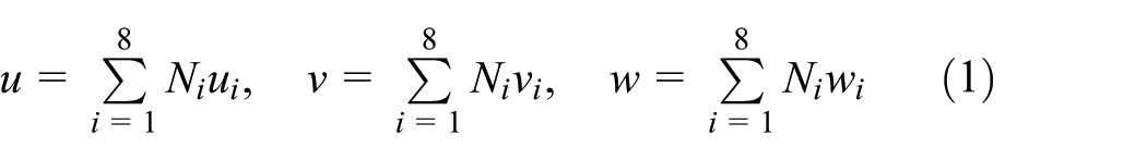
where


3D Desai interface element.
The coordinate transformation can be realized by

The Jacobian matrix of the 3D solid element can be expressed as

The element stiffness matrix is

The incremental constitutive condition of the 3D Desai element can be expressed as

which can be expanded as

where
Desai indicated that the normal stiffness of a thin-layer element is related to the material property of nearby soil elements and structural elements. Thus, the normal stiffness matrix of thin-layer element can be expressed as

where
According to the hyperbolic model, 22 normal stiffness can be expressed as
where
The strain-hardening hyperbola model is utilized to simulate the tangential stiffness of the interface element, which can be expressed as

where
To simulate the process of energy dissipation caused by the contact between pile and soil during an earthquake, damping item is added to the stress–strain relationship. To truly embody the nonlinear variance of the soil near the pile and the stiffness change in the interface element, Rayleigh damping is applied. Then, the damping matrix can be expressed as

where
A program of a user-defined element (UEL) is developed with Fortran language. The element node and Gauss integral point are arranged, and node force and node displacement are calculated. The modified Desai thin-layer element is 3D with eight nodes, which is compatible with the C3D8 element in ABAQUS. The developed program can be imported into ABAQUS directly through the subroutine interface.
Model verification
A simple pile–soil–structure interaction system was established to investigate the effect of damping in the modified Desai interface element on structural responses (Figure 2). The dimension of the soil model was 40 m × 40 m × 20 m. A concrete circular column was utilized as superstructure and pile. The superstructure part was 30 m long, and the pile part was 10 m. The elastic modulus of concrete was

Simple pile–soil–structure system.
Figure 3 shows the acceleration time histories at the column cap. It can be seen that the trend of acceleration time histories of the model with damped Desai element is approximately the same as that of the model with undamped Desai element. The model with damped Desai element exhibits lower acceleration responses, and the maximum reduction can be 9.93%.

Acceleration time histories at the column cap in the x-direction.
The envelope curves of acceleration time histories in the x-direction of the whole structure (column and pile) under damping and no damping occasions are shown in Figure 4. The acceleration response of the model with damped Desai element is lower than that of the model with undamped Desai element.

The envelope curves of acceleration time histories in the x-direction.
Figure 5 shows the surface diagram of shear force and bending moment of column with damped and undamped Desai elements in the x-direction. It is shown that all inner force responses of the model with damped Desai element are lower than that of the model with undamped Desai element. The reduction in peak shear force and bending moment are 7.6% and 8.7%, respectively.

The surface diagram of shear force and bending moment: (a) the shear force on no damping occasion, (b) the shear force on damping occasion, (c) the bending moment on no damping occasion, and (d) the bending moment on damping occasion.
Finite element model of the pile–soil–structure system
A pile–soil–structure system is established. The system includes soil and a frame structure with 8 floors, 4 columns and 4 piles for every column, as shown in Figure 6. The dimension of the soil is 50 m × 50 m × 30 m. For the piles, friction pile is utilized, and the diameter, length, and spacing distance are 0.4, 5, and 0.7 m, respectively. The pile cap dimension is 1.5 m × 1.5 m × 0.2 m. The dimensions of the frame are shown in Table 1.

Pile–soil–structure system: (a) entire model and (b) frame structure and pile foundations.
Dimension of the frame.

Material properties
Material properties for concrete
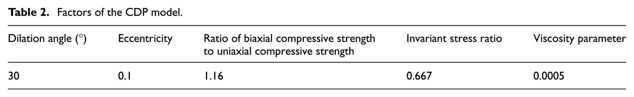
A concrete damage plastic (CDP) model is used for the superstructure and pile foundations to consider the effect of concrete failure on seismic responses. The specific factors of the CDP model are shown in Table 2. The density of concrete is
Factors of the CDP model.
Material properties for soil
The equivalent elastic model is utilized for the soil. The program of the equivalent elastic model is developed in Fortran language and imported into ABAQUS through a user-defined material (UMAT) interface. The specific factors of the equivalent elastic model are shown in Table 3.
Factors of the equivalent elastic model for soil.

Clarification of the equivalent elastic model
A simple free field model established in ABAQUS is used to clarify the equivalent elastic model as shown in Figure 7. The dimension of the model is 40 m × 40 m × 20 m. Three cosine acceleration time histories, as three-direction load, are input at the bottom of the model, which are

Free field model.
The hypothetical confining pressure in the soil.

Figure 8(a) and (b) shows the hysteretic stress–strain curve of top and bottom central elements, respectively. Residual plastic strain is not considered, which is consistent with the characteristic of the equivalent elastic model. It can be seen that the slope of hysteretic curve of the bottom element is larger than that of the top element, because the confining pressure at the bottom is larger.
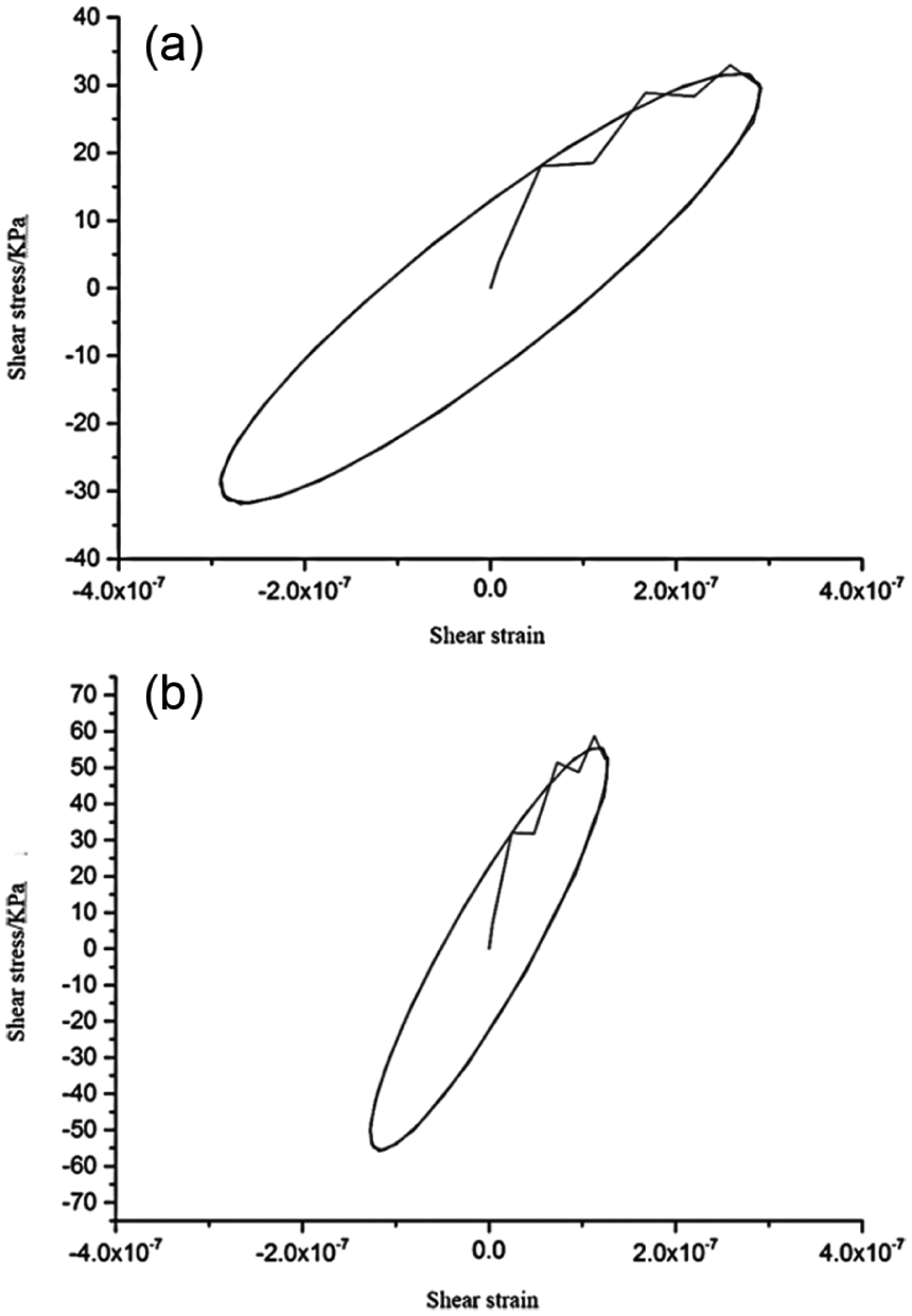
Hysteretic stress–strain curves of (a) top and (b) bottom central elements.
Figure 9 shows the acceleration time histories on the surface and bedrock, which are consistent basically. The consistence between these curves clarifies that the program of the equivalent elastic model can judge the inflection point accurately.

Surface and bedrock acceleration response.
The artificial viscoelastic boundary is utilized for the model edges and bottom again. The velocities of S wave and P wave are

N-S acceleration time history.

Response spectrum of N-S acceleration time history.
Discussion of the results
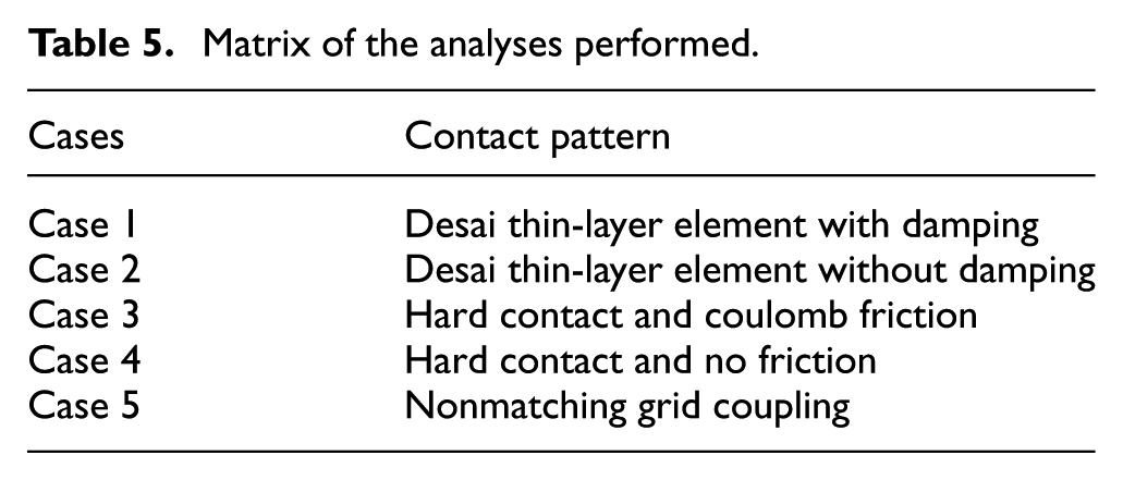
To study the effect of the modified Desai thin-layer element on the inner force responses of the 3D soil–pile–structure system, five different types of contact between pile and soil are applied in the model. A numerical analysis is performed for each case, and the results are compared. The study cases are shown in Table 5.
Matrix of the analyses performed.
Analysis of the inner force responses of the superstructure
Figure 12 shows the normalized peak inner force at the top of the frame column for each floor, including peak shear force, peak bending moment, peak axial force, and peak torque. Normalization is realized by dividing the results of cases 1–4 by that of case 5. In Figure 12, the value of case 2 is greater than that of case 1, except for the ratio of peak axial force. The trend of cases 1 and 2 is definitely different from that of cases 3 and 4 except for the ratio of peak axial force. This is because that the interaction methods of cases 1 and 2 and cases 3 and 4 are significantly different. The method based on interface element takes the variation of material property of soil and pile and a lot of contact behaviors into consideration, including bonding, slipping, gaping, and reclosing, which can accurately simulate the interaction between pile and soil. However, the method based on hard contact, friction, or frictionless behavior regards the pile and soil as rigid body without considering the material property variation.

Normalized peak inner force at the top of the frame columns for each floor: (a) ratio of N-S peak shear force of the frame column, (b) ratio of N-S peak bending moment of the frame column, (c) ratio of peak axial force of the frame column, and (d) ratio of peak torque of the frame column.
Figure 12(a) shows the comparison of the peak shear force of the frame columns, in which the trends of cases 1 and 2 and cases 3 and 4 are different. The curves of cases 1 and 2 fluctuate greatly, while the curves of cases 3 and 4 are stable. A comparison of the peak bending moments of the frame columns is shown in Figure 12(b). The curves of case 3 and case 4 descend monotonically from the first floor to the seventh floor, whereas the curves of cases 1 and 2 ascend, reach the maximum at the seventh floor, and then descend.
In Figure 12(c), the trend of each curve is identical, and all ratios are very close to 1; thus, the contact pattern has minimal influence on the axial force of the frame column. For the peak torque of the frame column, the results of cases 1–4 are all smaller than that of case 5. The results of cases 1 and 2 are obviously smaller than that of cases 3 and 4 from the first floor to the sixth floor. Numerical comparison of the peak inner force of the frame column between cases 1 and 2 is shown in Table 6.
Comparison of peak inner force of frame column between cases 1 and 2.

Analysis of the displacement responses of the superstructure
The absolute displacement responses of superstructure of cases 1–5 are analyzed and compared as shown in Figure 13, in which the displacement responses of cases 1 and 2 are more significant than that of cases 3–5. The vibration components of cases 1 and 2 are more abundant. This is because that in the contact methods used in cases 3–5, two contact objects are treated as rigid approximately, and the effect of constitutive relation variance on the interaction is not considered. In addition, in case 1, the Rayleigh damping is considered which contributes to the energy dissipation in the soil–pile interaction and to some extent constraints the displacement of pile so that the peak displacement of case 1 is smaller than case 2. Although there is no friction in case 4, hard contact is used, which provides more constraint for the interaction between soil and pile. This is because that Desai thin-layer element-based method considers the gaping and closing thoroughly, which lowers the constraint of soil to pile. However, hard contact–based method does not. The envelope curve of N-S displacement time history of the frame column is shown in Figure 14, in which the displacement responses of cases 1 and 2 are larger than those of cases 3–5 in different levels. The peak displacement of case 1 is smaller than that of case 2. The difference decreases along with the distance from column cap increases.

The comparison of N-S absolute displacement time history on the top corner point of the superstructure in the first 12 s.

The envelope curve of N-S absolute displacement time history of the frame column.
Analysis of the peak inner force of the group-pile foundation
The inner force of group-pile foundations is analyzed to determine the effect of the improved Desai thin-layer element. Figures 15 and 16 show the normalized N-S peak shear force and peak bending moment of piles, respectively. Note that two diagonal piles of one of the four group-pile foundations are chosen to be investigated which are named piles 1 and 2. Piles 1 and 2 are at the outside corner and inside corner, respectively. Normalization is realized by dividing the results of cases 1 and 2 by that of case 5.

Normalized N-S peak shear force of (a) pile 1 and (b) pile 2.
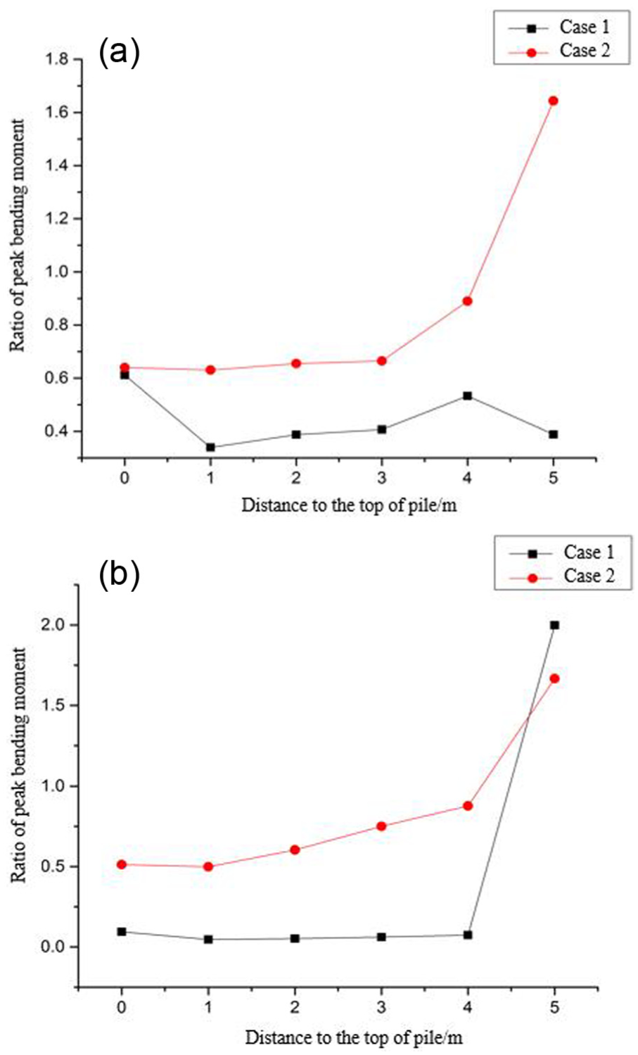
Normalized N-S peak bending moment of (a) pile 1 and (b) pile 2.
The peak shear force of case 1 is smaller than that of case 2 because of the damping in the interface element. It can be concluded that the Desai interface element without damping overestimates the shear force response of the pile. The peak shear force of case 1 is very close to that of case 2 at the top and bottom of the pile. For both cases 1 and 2, the maximum shear force appears in the position 1 m from the top of the pile, and the difference between the peak shear forces of cases 1 and 2 is more obvious in this position. For piles 1 and 2, the peak shear force of the pile of case 1 is 34.9% and 39.6% lower than that of case 2 in the position 1 m from the top of the pile, respectively.
Figure 16 reveals that the peak bending moment of pile 1 and 2 of case 1 is smaller than that of case 2. In Figure 16(b), maximum disparity reaches 80%. This finding indicates that using the Desai element without damping can overestimate the bending moment response of the pile. The ratio of the peak bending moment at the bottom of the pile is meaningless because all the peak bending moments of cases 1, 2, and 5 are very small.
Conclusion
Seismic response analyses for a 3D finite element model were performed to simulate a soil–pile–structure system with an improved Desai interface element during an earthquake. The numerical results showed that the peak inner force of the frame column of the model with improved Desai element can be approximately10% lower than that of the model with the original Desai element. The pile peak shear force of the model with the improved Desai element is at least 19.2% lower than that of the model with the original Desai element. With regard to the pile bending moment, maximum disparity reached 80%. Using the Desai element without damping would overestimate the bending moment response of the pile.
Footnotes
Academic Editor: Filippo Berto
Declaration of conflicting interests
The author(s) declared no potential conflicts of interest with respect to the research, authorship, and/or publication of this article.
Funding
The author(s) disclosed receipt of the following financial support for the research, authorship, and/or publication of this article: The project was financially supported by the National Nature Science Foundation of China (nos 51378234 and 51578261) and the Fundamental Research Funds for the Central Universities (no. 2015MS060).