
Abstract
In this article, we introduce a localization system to reduce the accumulation of errors existing in the dead-reckoning method of mobile robot localization. Dead-reckoning depends on the information that comes from the encoders. Many factors, such as wheel slippage, surface roughness, and mechanical tolerances, affect the accuracy of dead-reckoning. Therefore, an accumulation of errors exists in the dead-reckoning method. In this article, we propose a new localization system to enhance the localization operation of the mobile robots. The proposed localization system uses the extended Kalman filter combined with infrared sensors in order to solve the problems of dead-reckoning. The proposed system executes the extended Kalman filter cycle, using the walls in the working environment as references (landmarks), to correct errors in the robot’s position (positional uncertainty). The accuracy and robustness of the proposed method are evaluated in the experiment results’ section.
Introduction
Accurate localization information is very important for the navigation system of autonomous mobile robots in any environment. Dead-reckoning is one of the most popular techniques for robot localization. However, the dead-reckoning method depends on the information coming from the encoders, which is subject to many problems, some of which are slipping of the wheels, roughness of the ground surface, and tolerance rate of the machine. Therefore, an accumulation of errors can exist when using dead-reckoning.
The problem of estimation is widely solved by a powerful mathematical method called Kalman filter (KF) method. This method was invented in 1960 by RE Kalman.
1
KF technique is basically a combination of a set of equations that give a solution in recursive fashion to solve the problems that are discrete in nature. The outcome of this technique is the estimation of the past and future positions in an effective manner;
2
the best example is the estimation of the position and location of mobile robots (x, y, and
The aim of this research is to improve the localization accuracy of mobile robots, by adding the EKF and infrared (IR) sensor to the dead-reckoning method. Mobile robots need a solution that is not affected by other sources, which are uncertain of causing problems, to calculate the exact estimation of the current position. Keeping in mind all the above issues, KF is expected to be the best solution, because of its features for handling noisy sensor measurements, as it will be shown in this article. In our proposed system, two states are used to accomplish the goal of localization; each one has several steps; one is a prediction state and the other is the updating state. The proposed system executes the EKF cycle, using the walls in the working environment as references to correct errors in the robot’s position. The predicted state, which uses the kinematic model of the robot, is executed at the beginning, while the updated state is executed in a cycle, using the EKF with the walls as landmarks.
The remainder of this article is organized as follows. Section “Literature review” presents the related works. Section “Background” presents the background to the design, which includes a mobile robotics kinematic model, and dead-reckoning. KF is presented in section “KF.” Section “The proposed system” describes the proposed system. Section “Experiment” explains the experiment and results. The article’s conclusion is presented in section “Conclusion.”
Literature review
The first famous article of KF was published in 1960 by RE Kalman. 1 This article described how to solve the discrete-data linear filtering problem recursively. From that time, KF has become a subject of wide-ranging applications, mainly in autonomous navigation. KF can be described as a set of mathematical equations that offer an efficient computational (recursive) format to estimate the state of a process to reduce the mean of the error. KF is great in many aspects: its estimated, present, and future states. 8
Mobile robot localization is a challenging task; to solve this, many researchers have worked on it in the past by using many techniques which have been appearing in the literature for quite long time. In most of the techniques applied for solving mobile robot localization problem, the researchers have added some external source to the location of the robot, for example, Song and Seun 9 have applied gyro to solve the issue of slipping of the robot wheel; however, this has led to a disastrous high rate of drift in the wheel. Similarly, M Drumheller 10 used an external source in the form of ultrasonic ranging sensors to resolve the issue of localization; next, Kim and Seong 11 utilized magnetic compass as an external source to rectify the errors, but these magnetic fields got reflecting effects from other magnetic fields and also this effect increased from place to place in the indoor environment at different positions. Introducing a new sensor for reducing the error in the position of the robot is in itself an error. For example, adding a magnetic field will get affected by the other magnetic fields already in the system and reflection of the lasers, images causing shadows, and algorithms used to detect the low-level landmarks.
EKF is an enhanced version of KF and has been the most popular estimation algorithm in many applications. 12 EKF is based on a linear approximation to the KF theory. Several variations in the basic EKF have been designed that are proposed to reduce the effects of nonlinearities, non-Gaussian errors, ill-conditioning of the covariance matrix, and uncertainty in the parameters of the problem. 12 In general, mobile robot localization is called position estimation, which is an example of the general localization problem, the most basic perceptual problem in robotics. Several methods have been used for robot localization, but the dead-reckoning method is the most popular. However, dead-reckoning depends on the information that comes from the encoder. Many factors, such as wheel slippage, surface roughness, and mechanical tolerances, affect the accuracy of dead-reckoning. Therefore, an accumulation of errors exists in the dead-reckoning method.
Much research has been done to improve the dead-reckoning accuracy of mobile robots using EKF. In Reina et al., 13 Global Positioning System (GPS) data processing was used along with the adaptive KF in the real-time scenario. The weighted combination in between the new measurement and that of the predicted state at a given time k could be considered as the KF estimation. The error at the prior state is measured by a dynamic scale factor which leads to the implementation of this scheme, and its outcomes are measured depending on the error and the fading memory algorithm and fuzzy logic control.
A theoretical study on mobile robot localization based on EKF was studied by H Ahmada and T Namerikawa 14 on the measurement innovation characteristics. They introduced the uncertainties bounds of estimation by studying the measurement innovation to product good estimations even if with missing some measurements data. G Li et al. 15 used a fusion-based module with EKF for mobile robot localization. The fusion module consists of multi-sensor model (odometer, gyro, and laser radar model), environmental map, and robot motion model. In this research, the EKF is implemented using the fusion-based module to enhance the accuracy of the localization of wheeled mobile robot. L Dantanarayana et al. 16 used the EKF for mobile robot localization in occupancy grid maps. The proposed method required a prior knowledge about the initial robot position. It used laser scan placed within the occupancy grid maps. H Wang et al. 17 developed a genetic algorithm (GA)-fuzzy logic controller to modify the error covariance matrices of the EKF on-line. They used the GA to tune the membership functions of the fuzzy logic controller to increase the accuracy of the fuzzy logic controller. HG Todoran and M Bader 18 proposed a framework to reduce the error of simultaneous localization and mapping (SLAM) using the EKF, laser range scanner, and odometer measurements.
Background
The proposed localization system involves and integrates many techniques, such as a kinematic model of a mobile robot and the dead-reckoning method. Details of each concept are discussed in this section.
Kinematics model
The proposed technique is applied on wheeled mobile robot (WMR; Figure 1). WMR basically consists of total three wheels, of which two are in the front of the chassis with the same axis and act as driving wheels and the third is a free wheel which is toward the rear side of the chassis which is actually used to balance the mobile robot especially when it is moving.

Geometric description of WMR.
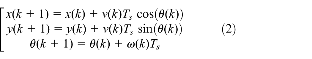
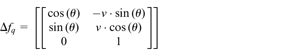
To get the motion and the orientation of the mobile robot, the above two wheels are driven independently with the help of actuators. In the below nonlinear equation, 19 the exact kinematic model of the mobile robot is explained

where the position of the mobile robot is indicated with the x- and y-coordinates, and the angle between the x-axis and the position direction, that is, its orientation, is indicated by
Dead-reckoning
The position and orientation of the moving WMR could be calculated by dead-reckoning. The current position and orientation of the robot t = tk+1 are calculated based on the previous readings of position and orientation of the robot at time t = tk. Using Euler approximation, equation (1) becomes
where the sampling time is represented by

The impulse of the encoder is represented as
KF
The ultimate goal of the KF technique is to solve the problem of estimation of the state

Robot position with and without use of the Kalman filter.
As can been seen from Figures 2 and 3, the mobile robot navigation is dependent on its previous navigation position

Robot position and states.
To estimate the exact current position, KF techniques rely on many equations which are mostly dependent on the previous position information. This

where A, B, and C are dependent on the system. The predicted measurement

This Xestimate is described as the current estimation state and it is a linear function of the predicted state, which actually is the difference between the measurement of prediction and the actual measurement, as corrected by Kalman gain and described by the following equation

The proposed system
The proposed mobile robot localization and its overall scheme which is the combination of both EKF and IR sensor are described in this section. In this proposed system, two sets of steps are followed to accomplish the goal of localization, one is the prediction state and the other is the updating state; the cycle approach is followed for the updating state. Figure 4 illustrates the complete proposed system.
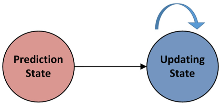
System states.
The proposed system executes the EKF cycle, using the walls in the working environment as references to correct errors in the robot’s position. The predicted state uses the kinematic model of the robot, executing at the beginning, while the update state executes in a cycle, using the EKF with the walls as landmarks. The inputs to the update state are the robot platform, the landmark (wall), and data from the IR sensors. Flowchart 1 illustrates the proposed system.
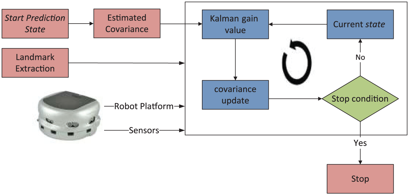
The proposed system.
The mobile robot platform used in this work is Khepera III; to calculate the distance between the wall and the Khepera, IR sensors were used. The test environment is shown in Figure 5. The proposed system in detail is explained in the rest of the article.

The test environment for the proposed system: (a) first test environment and (b) second test environment.
Used robot
K-Team Inc. 20 has developed the WMR Khepera III. Although it is very small in size, it still possesses almost all the functionalities of larger commercial robots usually used for research and education. It is basically a vehicle which is guided and designed to accomplish autonomous and intelligent tasks, as it is automated and driven differentially; Khepera III is illustrated in Figure 6.
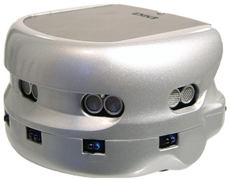
Khepera (side view).
The operation of the Khepera III platform is to act as a client within the client–server environment. The range-finders for Khepera are IR and ultrasonic sensors which are inbuilt; all the sides of the robot are covered with eight IR sensors. The IR sensors are equipped with the Khepera III robot. Therefore, any issues regarding the IR sensors (objects’ color, materials, and surfaces’ types) are dealt by the robot itself. Figure 7 depicts the Khepera IR sensors.

Khepera IR sensors.
Khepera III wheels are moved by a DC motor which gives 24 pulses per revolution, with a resolution of 600 pulses per revolution of the wheel. The pulse-width modulation (PWM) values of Khepera III have two ways of setting by a local motor controller or directly. The motor controller is used to control the speed or position of the motor; in other words, the DC motor controller is used to control the speed or determine the position. Figure 8 illustrates the structure of the motor controllers of Khepera III.
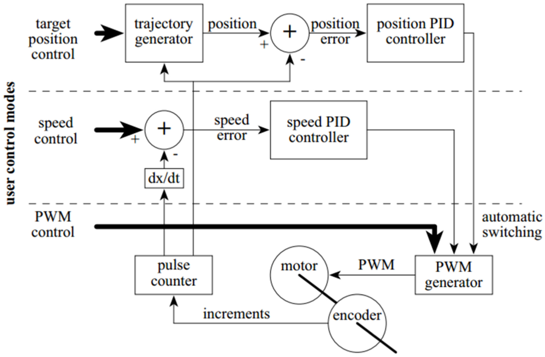
Structure of the motor controllers and levels of user access.
IR sensors’ fidelity
The ideal lighting conditions for the Khepera are uniform, constant, and clear light, but sensors are robust enough to function under most circumstances. Our lighting conditions are near ideal, as no direct light is spotted to the IR sensors, and the landmarks are painted with white non-glossy painting, as mentioned in the constructor K-Team, 21 in Figures 8 and 9.
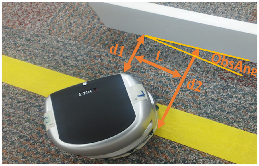
Relationship between robot and wall.
Predicted state
The kinematic model of the vehicle and the odometer is the base for the predicted state. We already explained the kinematic model in section “Kinematics model.” The prediction state used the kinematic equations with parameters that address the used robot (Khepera III) as follows


where the distance moved by the left wheel is indicated by D1 and the distance moved by the right wheel is indicated by D2, and the separation between the left and right wheels is measured by L (in this case, equal to 88.41). Figure 9 shows the Khepera robot and the wall and also their relationship.
The following equation defines the estimated covariance

where

Update step
To deal with the nonlinear uncertainties that exist in the robot localization, we studied the following equations to execute the update state for each cycle of the experiment


where W(k) is the extended Kalman gain, which has the following equations


The state of A1 and A2 changes depending on the direction of the wall with x- and y-axis; A1 = 1, A2 = 0 when the wall is in parallel direction to the x-axis, and A1 = 0, A2 = 1 when the wall is in parallel direction to the y-axis. The gradient of the observation for the noise is

where


The covariance update has the following equation

Experiment
The experimental part of this work was executed in a laboratory atmosphere, as shown in Figure 5. As discussed above, Khepera III, a WMR, was used in this work; it was manufactured by K-Team Inc. More information regarding the Khepera III is explained in used robot section. MATLAB is used as a programming platform language. We used a PC with the following specifications: Intel Core i7 Processor, 16 GB RAM, 120 GB hard drive, and Windows 8 64-bit Operating System. To evaluate the performance of the above-discussed method, two scenarios were demonstrated as shown in Figure 10. The first scenario was simple; it had two walls, one wall was parallel to the x-axis and the other wall was parallel to the y-axis. In this scenario, Khepera III moved from the starting point (0 cm, 0 cm) to the destination point (500 cm, 500 cm).

The experimental scenarios: (a) first scenario and (b) second scenario.
The path followed by the proposed system was compared with the robot’s dead-reckoning default for each scenario. The comparison included traveled distance, the traveled path, the execution time, and the standard deviation, as well as the maximum error. In the first scenario, Khepera moved from the starting point (0 cm, 0 cm) to the destination point (500 cm, 500 cm). The second scenario, more complicated than the first, used many discrete walls. In this scenario, Khepera moved from the starting point (0 cm, 0 cm) to the target point (1500 cm, 0 cm) through many midpoints: (500 cm, 0 cm), (500 cm, 1000 cm), and (1500 cm, 1000 cm).
While the robot was moving, the positions were measured and stored as x and y and were also plotted using the MATLAB.
Figure 11 illustrates the experimental results of the first scenario. As can be seen, the path resulting from the proposed system was more accurate than the robot’s default path using dead-reckoning. Figure 11 shows the photographs of the first scenario.

The execution of the proposed system in the first scenario.
As shown in Table 1, the statistical results suggest that the proposed system is more accurate than the robot’s default system (dead-reckoning) without a KF. In the first scenario (Figure 12), the maximum error in the proposed system was 1.5 cm, the standard deviation was 0.75, and the travel distance was 102 cm. Meanwhile, the maximum error in the robot’s default system for the same scenario was 1.9 cm, the standard deviation was 0.83, and the travel distance was 105 cm.
Statistical results.


Photographs of the experiment (first scenario).
The second scenario, more complicated than the first, used many discrete walls. In this scenario, Khepera moved from the starting point (0 cm, 0 cm) to the target point (1500 cm, 0 cm) through many midpoints: (500 cm, 0 cm), (500 cm, 1000 cm), and (1500 cm, 1000 cm). The position measurements x and y were stored during the movement of the robot and plotted by MATLAB. Figure 13 illustrates the experimental scenario for the proposed system. As Figure 13 shows, the path resulting from the proposed system was more accurate than that resulting from the robot’s default. Figure 14 shows the photographs of the second scenario.

Execution in the second scenario of the proposed system.

Photographs of the experiment (second scenario).
In the second scenario, the maximum error in the proposed system was 1.7 cm, the standard deviation was 1.1, and the travel distance was 357 cm. Meanwhile, the maximum error in the robot’s default system in the same scenario was 2.5 cm, the standard deviation was 1.3, and the travel distance was 362 cm.
We compared the accuracy of the proposed system with the work of N Ganganath and H Leung. 22 The comparison results are shown in Table 2, from near 1.8 m to far 3.8 m. The proposed system shows better results than the compared systems. The maximum error of the proposed system was 1.9 cm, while the errors in the compared odometer system, EKF, and particle filter (PF) system were 18.66, 11.79, and 4.46 cm, respectively.
Statistical results of compared systems.
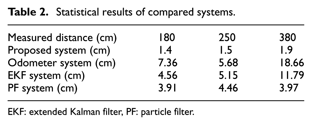
EKF: extended Kalman filter, PF: particle filter.
Conclusion
In this article, we have proposed a new system for mobile robot localization which is based on EKF combined with IR sensors. The proposed localization system used the EKF combined with IR sensors in order to solve the problems of dead-reckoning (slipping of the wheel, the roughness of the ground surface, tolerance rate of the machine, etc.). Khepera III robot was used to conduct the experiment. The detail description of the results shows the accuracy and robustness of the proposed method. In the future, we plan to use the proposed localization system with another robot and use the EKF with different landmarks, such as GPS coordinator, camera position, and wireless signal.
Footnotes
Acknowledgements
The authors extend their appreciation to the Deanship of Scientific Research at King Saud University for funding this work through research group no. RG-1437-018. Author Mohammed Faisal is now affiliated to College of Computer and Information Sciences (CCIS), Al-Muzahimiyah Branch, King Saud University, Saudi Arabia.
Academic Editor: Weicha Sun
Declaration of conflicting interests
The author(s) declared no potential conflicts of interest with respect to the research, authorship, and/or publication of this article.
Funding
The author(s) disclosed receipt of the following financial support for the research, authorship, and/or publication of this article: The authors extend their appreciation to the Deanship of Scientific Research at King Saud University for funding this work through research group no. RG-1437-018.