
Abstract
The contra-rotating fan is an electromechanical device in which electromagnetic force and aerodynamic force coordinate together. Its operation process is affected by multiple factors and is also coupled with multiple variables. In order to further reveal its working mechanism, electromagnetic-fluid coupling model for contra-rotating fan was presented and relevant numerical computations were performed by the combination of the motors’ electromagnetic-field simulation and the fan’s fluid-field simulation. Curves of electromagnetic torque and aerodynamic torque in time domain, respectively, for two motors and two impellers of the fan were obtained, and then fast Fourier transform algorithm was used to analyze their harmonic components. Meanwhile, the resonance effect induced by the same-frequency components between the harmonic electromagnetic and aerodynamic torques was investigated. Moreover, the impeller–motor interaction and matching performance were explored so as to determine the optimal combination scheme of blade number in two-stage impellers. The reasonableness of this scheme was validated experimentally. This heterogeneous physical-field simulation method targeted at electromagnetic-fluid coupling condition offers an important reference for optimizing the fan system.
Keywords
Introduction
Contra-rotating fan is a kind of axial flow fan with a special structure. Its front and rear impellers are installed directly on the shaft ends of two motors. The two impellers are working impellers as well as the guide impellers for each other. They spin in the opposite directions to form its contra-rotating structure. Due to this mechanical structure, contra-rotating fan has the advantages of high-pressure coefficient and good performance of reversing airflow. It has been widely used in mine ventilation, tunnel ventilation, boiler air blowing, and other long-distance air-providing cases. In practical applications, however, the contra-rotating fan has such problems as the difficulty in matching the two motors and severe electromechanical resonance of the whole system under certain working conditions. Therefore, further research into the working mechanism of the contra-rotating fan and identifying the key factors that influence its performance are of great theoretical value and practical significance.
Using the variable circulation design approach, a preferred design of contra-rotating fan with high pressure ratio and high efficiency was obtained. The fan performance at the design working point was analyzed, the distributive rules of radial load at the optimal operating point were determined, and the approximate descriptive mathematical expressions were given on the premise that the load distribution of the two motors were equivalent. 1 To understand the internal flow field of the contra-rotating fan, a three-dimensional (3D) model from the collector inlet to the diffuser outlet was built. Based on the velocity triangle of blade element, the authors selected the appropriate blade numbers of the front and rear impellers. 2 The noise-generation mechanism of the contra-rotating fan was theoretically analyzed, and an FW-H (Ffowcs Williams and Hawkings) model was used to calculate the aerodynamic noise intensity under different working conditions. The relevant results showed that changing the values of the aerodynamic parameters not only expanded the effective operating scope of the fan and improved the machine operation stability but also weakened the tip vortex turbulence intensity at the leakage area and reduced the noise. 3 The distributive conditions and attenuation trends of discrete noise and broadband noise in the air ducts of a contra-rotating fan were studied, and the effects of the blade number matching types on the aerodynamic noise were discussed. 4 Through full-circumference numerical simulation, the overall performances of a contra-rotating fan at different speed matching types of the front and rear motors were discussed. The authors concluded that the airflow and total pressure were related to the rotating speeds of the front and rear motors, and the rotational speed ratio should be adjusted within a certain range to achieve suitable performance for varying pipelines. 5 The SIMPLE algorithm was used to analyze the internal flow field of a contra-rotating fan under constant flow conditions and the pressure distributions on the two impellers were studied. It was found that the secondary flow was caused by the inverse pressure gradient at the blade tip. 6 The unsteady numerical simulation specific to the 3D full-scale model of a contra-rotating fan was carried out. A certain number of monitoring points were arranged at the key locations of the flow field around the two impellers, and then the pressure data at these monitoring points within a certain number of rotation periods were collected.7,8 The pressure fluctuation curves in frequency domain were presented, and then pulsation frequency components, intensity and causes were analyzed. The effects of airfoil parameters and airflow parameters on the aerodynamic loads of the rear impeller were studied. The appropriate selection of blade installation angles of front and rear impellers could theoretically reduce the aerodynamic force acted upon the blades of rear impeller and reasonably distribute the loads between the two impellers. 9
From the above literature review, it can be found that current research for contra-rotating fan are focused mainly on the experimental tests and numerical simulations, optimization design of mechanical parts, aerodynamic noises, and overload of rear motor. The focuses of these researches are relatively independent, and the research on the interactions of these aspects is not sufficient. The contra-rotating fan is a mechanical-electromagnetic tightly coupled unified system, and the two impellers are directly driven by the individual motors. The blade–air interaction would generate extra pulsating torque components on the two rotors. The resonance between the pulsating torque and motor electromagnetic torque may lead to a severe mechanical vibration. This vibration directly reduces the operational efficiency of the contra-rotating fan and will have a devastating impact on the fan. Therefore, the real working conditions and operation mechanism cannot be accurately reflected simply from the perspective of electromagnetism theory or fluid dynamic theory.
According to the structural characteristics of the contra-rotating fan, this article established the electromagnetic-fluid coupling simulation model. Through the intermediate platform and interface, the shafting torque values as coupling variables were exchanged between the electromagnetism simulation model and the mechanical simulation model. The magnetic density distributions of the two motors and the blade aerodynamic force distributions of the two impellers were analyzed when the contra-rotating fan operated at appointed working points. Meanwhile, the electromagnetic torque and the aerodynamic torque curves in the time domain were plotted and then transformed to the frequency domain to analyze the electromechanical resonance effect between the motor harmonic torque and the load harmonic torque. On this basis, the corresponding strategy for structural improvement of the prototype fan was proposed. Finally, four design schemes of blade number combinations were compared and the optimal blade numbers of the front and rear impellers were determined. Relevant experiments testified the accuracy and effectiveness of analysis model and computation method in this study.
Electromagnetic-fluid coupling model of the contra-rotating fan
To obtain the electromagnetic-fluid coupling model of the contra-rotating fan, first establish the 3D electromagnetic-field simulation model and the 3D fluid-field simulation model in the Maxwell and Fluent of ANSYS, respectively. Then, set the data exchange interface and coupling time. The two-way data transmissions were performed with the shafting torque as the coupling physical quantity. For each time step, one electromagnetic-field computation and one fluid-field computation were conducted. The outputs were exchanged and used as the inputs of the next period of computation. The electromagnetic-fluid coupling simulation model of contra-rotating fan is shown in Figure 1.

Electromagnetic-fluid coupling simulation model of contra-rotating fan.
Physical model
The two impellers are directly driven by two three-phase induction motors with rated voltage of 380 V and rated power of 7.5 kW. The numbers of stator and rotor slots are 24 and 31, respectively. Hub stagger angles of 43° and 25.5° were chosen for the front impeller with 13 blades and rear impeller with 11 blades, respectively. The main geometry dimensions of the numerical simulation model are shown in Table 1.
Geometry dimensions of the model (mm).

Finite element analysis of electromagnetic field
3D finite element theory
To simplify the calculation, during the 3D finite element analysis of electromagnetic field, it is assumed that the conductivity rate and permeability rate are merely functions of space, and the motor ferromagnetic material is isotropic, meanwhile excluding the impact of displacement current and ignoring the skin effects of current-carrying conductors and the stator iron.10,11 In consideration of the magnetic saturation effect, the 3D electromagnetic-field equations in boundary value form are expressed as

where
For the 3D transient electromagnetic field, besides the transient electromagnetic process, the transient mechanical process should also be considered. Therefore, the discrete calculation of mechanical displacement is carried out, and its discrete form is expressed as

where
Implementation of the numerical simulation
The 3D transient electromagnetic-field solver was chosen, and the 3D geometric model of the motor was established using the rapid modeling module in Maxwell 16.0. The corresponding parameters were set according to the material property, and different materials were assigned to the individual parts of the motor. In this simulation, steel type of the motor core is DW465_50. The three voltage excitations with the phase difference of 120 degrees were assigned to the three-phase stator windings, respectively, while the rotor winding of the squirrel cage type belonging to the induced current winding requires no excitation. Considering that the solved region is large enough and the magnetic line of force is parallel to the stator cylinder, the boundary conditions were set by the software automatically. The electromagnetic field of the motor was divided by unstructured tetrahedral meshes, and it was prepared for entering into simulation calculations.
Finite element analysis of fluid field
3D finite element theory
To simplify the calculation, during the 3D finite element analysis of fluid field, it is assumed that the fluid is incompressible, meanwhile ignoring the buoyancy and gravity of the fluid at standard atmospheric pressure. The fluid flow inside the contra-rotating fans is a kind of turbulent flow, and the main parameters of the turbulent flow vary at random. Nonetheless, continuity equation and Navier–Stokes equation were still applicable12,13

where P is the pressure on the micro-fluid unit (N/m2), µf is the dynamic viscosity (N s/m2), Si is the generalized source term, ρ is the fluid density (N s2/m4), u and u′, respectively, represent the mean value and the fluctuating value of the velocity components (m/s). Subscripts i and j are coordinates, and i or j = 1, 2, 3 are the corresponding components in the x, y, and z directions, respectively.
In the equation, an additional Reynolds stress appears at the right side of the time-averaged momentum equations. The relationship between stresses and the mean velocity gradient is

where Cµ is the turbulent viscosity constant, K is the turbulent kinetic energy (m2/s2), ε represents the turbulent dissipation rate (m2/s3), and δij is the Kronecker delta.
Implementation of the numerical simulation
The 3D geometric model of the fan was established in Solidworks 2016. Then, the global flow field of the established model was also divided by unstructured tetrahedral meshes in Fluent 16.0. Note that the Renormalization group (RNG) K − ε model was chosen for fully developed turbulence loses effectiveness near solid walls where inertial forces are overwhelmingly larger than viscous forces. Standard wall functions were used to associate physical quantities in the wall region with corresponding quantities in the core region. The boundary conditions were set for the velocity inlet and pressure outlet. Turbulence intensity and hydraulic diameter were selected for the specified method of turbulence and calculated values were assigned. The region of the two impellers was defined as the rotation region, and the contra-rotating impellers were dealt with using the multiple reference frames (MRF). The no-slip condition was imposed on the wall surface in contact with fluid, and it was prepared for entering into simulation calculations.
Operating points and performance curves of the contra-rotating fan
The operating points and relevant performance curves of the prototype fan can be obtained by simulations and experiments. The Type C1-C test equipment, with the pipe length of 2200 mm and the pipe diameter of 700 mm, is shown in Figure 2. The flow rate was controlled by changing the vent number on the inlet block cardboard and measured by a Venturi nozzle. The shaft powers of the two motors were measured by electrometric method. Meanwhile, electromagnetic-fluid coupling model of the prototype fan was numerically simulated. The total pressure Pt, the overall efficiency (ratio of fan efficient power to motor input power), and shaft powers of front and rear motors (SFM and SRM, respectively) under different flow rates were obtained. According to the test results and simulation results, the characteristic curves of the prototype fan were plotted in Figure 3. Obviously, the simulation results are very similar to the test ones. When the changing of flow rate happens, the SFM varies within a small range, while the SRM changes in a relatively large range. At the flow rate of 11,782 m3/h, the Pt is about 2700 Pa, corresponding to the optimal point with the highest overall efficiency. For an operating point at the right side of the optimal point, the SFM is larger than the SRM; for an operating point at the left side of the optimal point, the SFM is smaller than the SRM.

Test equipment of contra-rotating fan: (a) test device and (b) operator console.

Characteristic curves of the prototype fan: (a) Q–Pt and Q–Efficiency curves and (b) Q–SFM and Q–SRM curves.
At different operating points, the shaft torques of the front and rear rotors change differently. To probe into the coupling interaction between motor electromagnetic torque and load aerodynamic torque, the shaft torques of fan rotors in time domain and frequency domain were analyzed. Here, the conditions of shaft torques at the optimal point were presented in order to illustrate this process. At the optimal point, the magnetic density distributions of the two motors and the blade aerodynamic force distributions of the two impellers are shown in Figures 4 and 5. The magnetic intensity of the rear motor is relatively larger (Figure 4). At this moment, the winding current effective value and electromagnetic torque average value of the rear motor are both greater than those of the front motor. When the air flows through the blades of the two impellers, the leading edge of the blade, which contacts the airflow first, is imposed upon the maximum aerodynamic force (Figure 5). As the airflow moves forward, the aerodynamic force imposed on the blade gradually decreases and is minimized at the trailing edge. Thus, it is necessary to ensure that the leading edge of the blade has sufficient strength to avoid the blade deformation or even breakage due to excessively large aerodynamic force.

Magnetic density distributions of the front and rear motors.

Blade aerodynamic force distributions of the front and rear impellers.
Calculation of shaft torques for contra-rotating fan
Calculation of electromagnetic force and electromagnetic torque
The electromagnetic force of the two motors can be calculated using Maxwell tension equation. Suppose the magnetic field intensity on surface A of the affected object is H. When this object is surrounded by air, the electromagnetic force imposed on this object is

After the decomposition of x and y directions


where
Electromagnetic torque is determined via equivalent circuit method and expressed as

where the first item at the right side is the electromagnetic torque of the fundamental wave, which is generated from the fundamental wave component of the rotor current; the second item is the stable harmonic wave torque, which is generated by the interaction of the motor harmonic current and harmonic magnetic flux with the same frequency. The third item is the fluctuation harmonic torque, which is generated from the interaction between the motor harmonic current and harmonic magnetic flux with different frequency. 14 Their expressions are as follows


where n is the motor rotation speed (r/min);
Figure 6 shows the transient electromagnetic torque curves of the two motors within a rotor revolution period. If the slope of the mechanical characteristic curves is small enough, even if the load torque is changed, the motor rotation speed can remain basically unchanged, while the electromagnetic torque only fluctuates within a small range. However, Figure 6 shows that the electromagnetic torques of the front and rear motors of contra-rotating fan fluctuate largely, the working conditions of the rear motor are especially unstable, as the amplitude of the upper and lower fluctuations is about 2 N m. This is because the load of the motor is not inertial load, and the harmonic electromagnetic torque cannot be eliminated. When the fluctuation amplitude of the motor electromagnetic torque rises, besides the increase of copper loss in the motor stator, the stator current fluctuation component would generate eddy current inside the iron core of the motor, thereby increasing the motor iron loss and reducing the overall efficiency of the contra-rotating fan. Thus, the fluctuation amplitude of electromagnetic torque between the front and rear motors should be decreased, so as to reduce the energy consumption of the fan system.

Electromagnetic torque curves of two motors in time domain.
Calculation of aerodynamic force and aerodynamic torque
The aerodynamic force on the blades depends on the relative velocity between the air and blade. 15 The x- and y-direction components of the aerodynamic force imposed on per unit length airfoil section of the fan blades are expressed as
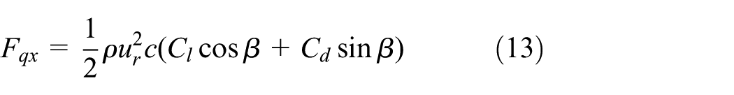

where
The aerodynamic torque can be calculated from the tangential aerodynamic force which is expressed as follows
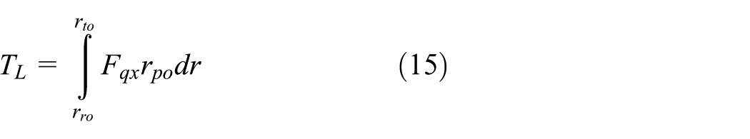
where
Figure 7 shows the transient aerodynamic torque curves of the two impellers within a rotor revolution period. The aerodynamic torque amplitude of the rear rotor fluctuates larger than that of the front rotor. The fluctuation range of the rear rotor load aerodynamic torque is similar to that of the motor electromagnetic torque, as both are 2 N m. A larger fluctuation of load aerodynamic torque means that the internal turbulent intensity of the fan is very large, the turbulent flows in different scales consume a large amount of energy, and the mechanical loss in the process of the air flowing is also increased. Thus, the fluctuation amplitude of aerodynamic torque between the front and rear impellers should be reduced so as to decrease the energy consumption of the contra-rotating fan.

Aerodynamic torque curves of two impellers in time domain.
Analysis of electromagnetic torque and aerodynamic torque in frequency domain
Resonance might occur when the motor electromagnetic torque and the load aerodynamic torque contain the same-frequency harmonic components. The fast Fourier transform (FFT) was used to analyze the electromagnetic torque and aerodynamic torque in Figures 6 and 7, respectively. The frequency of the fundamental frequency shown in the resulting spectrograms is 50 Hz. The constant torque components of the front motor and front impeller load are 26.73 and 26.68 N m respectively, while the corresponding torque frequency spectrogram is shown in Figure 8(a). The constant components of the rear motor torque and rear impeller load torque are 26.93 and 26.88 N m, respectively, while the corresponding torque frequency spectrogram is shown in Figure 8(b). It is obvious that, at the optimal point, the front and rear motors are both running in the vicinity of the rated torque, while the front and rear impellers are basically distributed with equivalent load.

Electromagnetic torque and aerodynamic torque of the prototype fan in frequency domain: (a) the front rotor and (b) the rear rotor.
If the harmonic electromagnetic torque and the harmonic aerodynamic torque with the same frequency have relatively large amplitudes, the corresponding frequency point is defined as the potential resonance point. This study only focuses on the resonance points with the two harmonic torques which are both larger than 0.05 N m. The front rotor has two resonance points, with the resonant frequency of 300 and 650 Hz, respectively (Figure 8(a)). At 300 Hz, the amplitudes of harmonic components are 0.133 and 0.221 N m, respectively. At 650 Hz, which is close to the blade-passing frequency of front impeller, the harmonic component amplitudes of the two groups of torques are maximized to 0.357 and 0.398 N m, respectively. The rear rotor has three resonance points, with the resonant frequency of 250, 300, and 550 Hz, respectively (Figure 8(b)). At 250 Hz, the amplitudes of harmonic components are 0.168 and 0.221 N m, respectively. At 300 Hz, which is close to the blade-passing frequency of the rear impeller, the amplitudes of harmonic components are 0.258 and 0.198 N m, respectively. At 550 Hz, the harmonic amplitudes of the two groups of torques are maximized to 0.305 and 0.364 N m, respectively.
Effects of blade number combination on fan performance
In the modeling process, 3D laser scanning technology was utilized to reconstruct the blades. Anchor points were first pasted onto the blade surface in an irregular pattern, and the impeller was then scanned repeatedly to generate a dense point cloud. 16 The high-precision simulation models of contra-rotating impellers under different blade number combinations were obtained, and then the corresponding numerical computations were finished. At the optimal point, the performance parameters of the contra-rotating fan under four blade number combinations are shown in Table 2.
Characteristic parameters under four blade number combinations of the two impellers.

To analyze how the shaft torque of the contra-rotating fan changes at the optimal point, FFT method was used to decompose the temporal curves of shaft torque. All the potential resonance points of motor electromagnetic torque and load aerodynamic torque for the four blade number combinations were found out. The front rotor has four resonant frequencies of 250, 300, 600, and 650 Hz, respectively. The rear rotor also has four resonant frequencies of 250, 300, 500, and 550 Hz, respectively. The torque harmonic amplitude histograms of each resonant frequency at the four blade number combinations of 13/11, 12/11, 13/10, and 12/10 are shown from left to right in Figure 9.

Electromagnetic torque and aerodynamic torque under four blade number combinations of the two impellers: (a) the front rotor and (b) the rear rotor.
The resonance points at the blade number combination of 13/11 have been discussed in the previous section. For the blade number combination of 12/11, the front rotor has two resonance points with the resonant frequency of 300 and 600 Hz. At 600 Hz, which is close to the blade-passing frequency of the front impeller, the harmonic component amplitudes of the two groups of torques are maximized to 0.205 and 0.319 N m, respectively. The rear rotor has two resonance points with the resonant frequency of 250 and 550 Hz. At 550 Hz, which is close to the blade-passing frequency of the rear impeller, the harmonic component amplitudes of the two groups of torques are maximized to 0.147 and 0.245 N m, respectively. For the blade number combination of 13/10, the front rotor has two resonance points with the resonant frequency of 250 and 650 Hz. At 650 Hz, which is close to the blade-passing frequency of the front impeller, the harmonic component amplitudes of the two groups of torques are maximized to 0.306 and 0.388 N m, respectively. The rear rotor has three resonance points with the resonant frequency of 250, 300, and 500 Hz. At 500 Hz, the harmonic component amplitudes of the two groups of torques are maximized to 0.146 and 0.302 N m, respectively. For the blade number combination of 12/10, the front rotor has two resonance points with the resonant frequency of 250 and 600 Hz. At 600 Hz, which is close to the blade-passing frequency of the front impeller, the harmonic component amplitudes of the two groups of torques are maximized to 0.144 and 0.201 N m, respectively. The rear rotor only has one resonance point with the resonant frequency of 500 Hz. The harmonic component amplitudes of the two groups of torques are 0.125 and 0.186 N m, respectively. The resonance properties under four blade number combinations of the two impellers are shown in Table 3.
Resonance properties under four blade number combinations of the two impellers.

Simulation results show that the harmonic torque component with the maximum amplitudes of the front and the rear rotors corresponding to the resonant frequency is approximately equal to the blade-passing frequency and has the largest number of resonance points, and the efficiency of the whole system is relatively low. The blade passing frequency is related to the number of blades, so the resonance points change with the blade’s number. Thus, the overall performance of the contra-rotating fan, the fluctuation amplitude of the harmonic torque, and the number of resonance points should be considered when selecting the blade numbers for the front and rear impellers. Through comparative analysis, the blade number combination of the prototype fan is adjusted to 12/10.
Vibration test on contra-rotating fan
To reveal the internal relationship between the torque resonance point and the vibration of the contra-rotating fan, experimental tests were conducted. Before the experiments, the contra-rotating fan was directly and tightly fixed on a solid test bed to achieve a rigid support. As is shown in Figure 10, the two vibration sensors are installed at the end bearing parts of the front and rear motors and then the wiring leads are connected to the indicator. The deviation between the installation direction and the measuring direction is smaller than ±5°. When the contra-rotating fan ran at the optimal point under different blade number combinations, the vibration amplitudes of front and rear motors were measured. The measurement results of the tests corresponding to the blade-passing frequency are shown in Table 4, where Ex, Ey, and Ez are the horizontal, vertical, and axial vibration amplitudes, respectively, with µm as the measuring unit.

Wiring diagram of vibration sensor: (a) internal winding diagram and (b) external winding diagram.
Vibration amplitude under four blade number combinations of the two impellers (µm).

Obviously, the vibration amplitude of the rear rotor is larger than that of the front rotor under each of the four blade number combinations. The motor vibration consumes electric energy, and excessive vibration induces not only the loosening or even drop-out of structural parts but also mutual friction between the stator coil and the shell, leading to the destruction of motor insulation and even the burn-down of motors. Therefore, in the design of the driving motors, the internal insulation of the rear motor should be strengthened and the vibration amplitude of the rear motor was within the predetermined range. Comparative analysis shows that the amplitude of mechanical vibration is minimized when the blade number combination of the front and rear impellers is 12/10.
Conclusion
In order to reflect the interaction effects between the electromagnetic field and fluid field of the contra-rotating fan, numerical simulations and experimental tests were carried out in this article. Through numerical simulation, the practical working conditions of the contra-rotating fan at appointed operating points can be obtained and the corresponding performance parameters can also be determined.
The numerical simulation results based on the electromagnetic-fluid coupling model show that the electromagnetic torque and the aerodynamic torque amplitudes are relatively large at the blade-passing frequency. The blade number combinations of the front and rear impellers have impact on the resonance points, which are related to the vibration amplitude in certain scope. The fan vibration amplitude is related to the number of resonance points, and the vibration frequencies of the two motors are close to the blade-passing frequency. The resonance analysis under the simulation environment reflects the real vibration phenomenon of the motors. Further tests and simulation computation show that changing the blade number combination of the front and rear impellers is helpful to the electromechanical resonance attenuation of the prototype fan at the optimal point and other working points.
Compared with the front motor, the internal magnetic field of the rear motor is more likely to get saturated when the contra-rotating fan is operating at the optimal point. The experimental results show that the vibration phenomenon of the rear motor is more obvious for any of the four blade number combinations. Therefore, in selecting the matching motors used to drive the contra-rotating fan, the running performance requirements should be taken into account to guarantee the safety and reliability of the whole system.
Footnotes
Academic Editor: Ming-Jyh Chern
Declaration of conflicting interests
The author(s) declared no potential conflicts of interest with respect to the research, authorship, and/or publication of this article.
Funding
The author(s) disclosed receipt of the following financial support for the research, authorship, and/or publication of this article: Financial support for this work was provided by the National Natural Science Foundation of China (grant no. 51275137).