
Abstract
To remedy the existing problems concerning vehicle handling for the heavy vehicle hydraulic power steering system, this article investigates a type of electronically controlled hydraulic power steering system, which can realize variable assistance characteristics and improve high-speed steering feel. To this end, a controlled electrohydraulic proportional valve is mounted in parallel with the rotary valve to regulate the flow rate through the rotary valve on demand according to vehicle speed and steering rate. After a system description in terms of structure and working principle, mathematical modeling of the electronically controlled hydraulic power steering system, vehicle, and steering resistance is conducted. To realize accurate tracking of valve spool displacement under parameter uncertainty and external disturbance, an adaptive dynamic surface control scheme is proposed for the electrohydraulic proportional valve. Numerical simulations and field tests are performed to validate the effectiveness and applicability of the electronically controlled hydraulic power steering system. The results show that the electronically controlled hydraulic power steering system can significantly improve high-speed steering feel compared with the hydraulic power steering system while maintaining the similar performance of low-speed steering portability.
Introduction
Nowadays, almost every modern vehicle uses a power steering system to help the driver steer. The most popular power steering systems in the automotive market can be divided into three types, namely, hydraulic power steering (HPS) system, electrohydraulic power steering (EHPS) system, and electric power steering (EPS) system.1–6 The HPS system was developed by American companies around the 1950s and has achieved a high level of acceptance during the last six decades due to its high power density and reliability. To date, heavy vehicles like buses and trucks have been widely equipped with the recirculating ball-type HPS system. 7 Nevertheless, there exist some problems concerning vehicle handling for the HPS system, which comprises a constant flow pump driven by the engine, an open-center rotary valve, and an assistance cylinder. In addition to the valve geometry, the cylinder pressure for generating steering assistance is positively correlated to the flow rate through the rotary valve that is nearly equal to the pump flow rate. Since the engine-driven pump outputs constant flow rate, the assistance performance cannot be changed. 8 Moreover, to ensure low-speed steering portability, the HPS system is dimensioned for the parking situation where the required steering assistance is the highest considering the greatest resistance. 9 As a result, it reduces the driver’s steering feel during high-speed driving when the need for steering assistance is comparatively low.
With the development of mechatronics technology, the EHPS and EPS systems, which were developed by Japanese companies around the 1980s, have been incorporated in many passenger cars in recent years. In the EHPS system, the pump is driven by a controlled electric motor to provide the flow rate on demand according to vehicle speed and steering rate, which makes it possible to realize variable steering assistance. 10 However, when it comes to heavy vehicles, the EHPS system may be problematic for application because the 24 V on-board power supply is insufficient to actuate the electric motor for steering assistance due to the greater axle loads of heavy vehicles compared with passenger cars. In the EPS system, a controlled electric motor is directly mounted on the steering column or the steering gear to provide variable steering assistance, eliminating the hydraulic components and simplifying manufacturing and maintenance. 11 Nevertheless, considering the utilization of electric motor, the EPS system has the same limitation as the EHPS system for heavy vehicle application.
To remedy the aforementioned problems for the heavy vehicle HPS system, a type of electronically controlled hydraulic power steering (ECHPS) system was proposed. 12 Based on a slight modification to the recirculating ball-type HPS system, the ECHPS system can realize variable assistance characteristics and improve high-speed steering feel. To this end, a controlled electrohydraulic proportional valve (EHPV) is mounted in parallel with the rotary valve to regulate the flow rate through the rotary valve on demand according to vehicle speed. 13 Guo et al. 14 researched the parameter optimization of the rotary valve in the ECHPS system to increase the alterable assist effort range. Geng et al. 15 presented the alterable assist characteristics of ECHPS system under different speeds by simulation. However, few of previous studies were verified by experiments. Moreover, the factor of steering rate also influences the demand of the flow rate through the rotary valve, which will be considered in this article.
In general, the comprehensive performance of the ECHPS system is very much dependent on accurate control for the EHPV. Due to inherent uncertainty and strong nonlinearity, EHPVs can be regarded as a class of uncertain nonlinear systems. Moreover, EHPVs will be inevitably affected by disturbances such as friction forces and forces exerted by the fluid in practical applications. During the past 15 years, the dynamic surface control (DSC) technique has proved to be efficient for dealing with large time-varying parameter uncertainty and external disturbances. 16 By now, various adaptive DSC controllers have been developed for a variety of nonlinear systems, such as flexible-joint robots, servo systems, DC-DC buck converter, electrohydraulic actuator, hypersonic flight vehicle, and permanent magnet synchronous motors.17–22 To the best of our knowledge, the adaptive DSC method has been rarely used for the control of EHPVs yet.
Inspired by previous work, this article presents an analysis of the ECHPS system in terms of modeling, control, and experiment study. First of all, a system description is given. Then, mathematical modeling of the ECHPS system, vehicle, and steering resistance is conducted. Moreover, an adaptive DSC scheme is proposed for the EHPV to realize accurate tracking of valve spool displacement under parameter uncertainty and external disturbance. Finally, numerical simulations and field tests are performed to validate the effectiveness and applicability of the ECHPS system.
System description
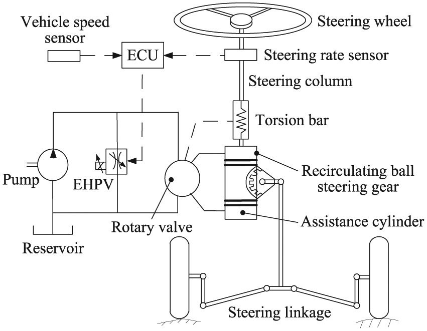
The ECHPS system under consideration is illustrated in Figure 1. It is composed of three subsystems: (1) a mechanical steering subsystem comprising a steering wheel, a steering column, a torsion bar, a recirculating ball steering gear, and steering linkages; (2) a hydraulic assistance subsystem composed of a constant flow pump driven by the engine, an open-center rotary valve, and an assistance cylinder; and (3) an electronic control subsystem consisting of an EHPV, an electronic control unit (ECU), and vehicle speed and steering rate sensors.
ECHPS system.
The rotary valve is mechanically connected to the torsion bar. Moreover, the mechanical part of the recirculating ball steering gear consists of a steering screw, a steering nut, a sector, and recirculating balls. To simplify the structure for manufacturing, the rotary valve and assistance cylinder are integrated into the recirculating ball steering gear to constitute the integral power steering gear, where the steering nut acts as the piston of the assistance cylinder.
It should be noted that the modification to the recirculating ball-type HPS system lies in the electronic control subsystem including the EHPV. The schematic of the EHPV being used is shown in Figure 2. It is made up of a valve body, a valve spool with integrated armature, an amplifier, a spring, an inlet nut, an adjustable bolt, solenoid coils, and magnetic-isolated rings. The EHPV is controlled by the ECU. By varying the input voltage of the amplifier, the current of the solenoid coils is regulated, changing the magnetic force that determines the valve spool displacement, opening area of the EHPV orifice and flow rate through the EHPV. Note that the greater the input voltage of the amplifier, the greater will be the valve spool displacement and flow rate through the EHPV.

Schematic of EHPV.
When the driver applies a steering wheel torque, the twisting of the torsion bar will activate the rotary valve, creating the assistance cylinder pressure that helps the driver steer. As mentioned previously, the cylinder pressure for generating steering assistance is positively correlated to the flow rate through the rotary valve, and the need for steering assistance decreases with vehicle speed. Therefore, considering the factor of steering rate, the flow rate through the rotary valve should be regulated on demand, which gradually decreases with vehicle speed and increases with steering rate at a certain vehicle velocity since more flow is needed to fill the cylinder. Note that the pump’s constant flow rate is equal to the summation of the flow rate through the rotary valve and EHPV. To ensure on-demand flow rate regulation, the desired valve spool displacement gradually increases with vehicle speed and decreases with steering rate at a certain vehicle velocity. In this article, the pump flow rate is 18 L/min and the maximum valve spool displacement is 2.5 mm. To realize the assistance characteristic curve shown in Figure 3, the desired flow rate through the rotary valve and desired valve spool displacement are listed in Tables 1 and 2, respectively.

Assistance characteristic curve.
Desired flow rate through rotary valve.

Desired valve spool displacement.

Mathematical modeling
ECHPS system
The equations of motion for the mechanical steering subsystem can be described as


where Jsw and Bsw are, respectively, the moment of inertia and viscous damping coefficient of the steering wheel and column. Ktb is the torsion bar stiffness. θsw and Tsw are, respectively, the steering wheel angle and torque. Jss, Bss, θss, F, and L are, respectively, the moment of inertia, viscous damping coefficient, angle, axial force, and center distance of the steering screw. Msn, Bsn, and xsn are, respectively, the mass, viscous damping coefficient, and displacement of the steering nut. pac and Ap are, respectively, the pressure and piston area of the assistance cylinder. Js, Bs, θs, Fs, and rs are, respectively, the moment of inertia, viscous damping coefficient, angle, force, and reference radius of the sector. Tp is the steering resistance.
The hydraulic assistance subsystem is illustrated in Figure 4. The rotary valve is modeled as a Wheatstone bridge with opposite orifices assumed to be equal. The flow rate and pressure equations are described as


where Qpump is the pump flow rate. QEHPV, Qrv, and Qi (i = 1, 2, 3, 4) are, respectively, the flow rate through the EHPV, rotary valve, and rotary valve orifices. Qac and vp are, respectively, the flow rate and piston velocity of the assistance cylinder. ωsw is the steering rate, and s is the lead of the steering screw. Cd is the flow coefficient, Ai (i = 1, 2) are the opening areas of rotary valve orifices, and ρ is the oil density. prv is the inlet pressure of the rotary valve. pleft and pright are, respectively, the left and right chamber pressures of the assistance cylinder.

Hydraulic assistance subsystem.
Figure 5 shows the schematic of the EHPV orifice, which is chosen as L-shaped. Based on the working principle of the EHPV, the following mathematical models are obtained


where ku is the amplifier gain, and ue is the input voltage of the amplifier. uc, i, Rs, Ls, and ke denote the voltage, current, resistance, inductance, and back-electromotive force (EMF) coefficient of the solenoid coils, respectively. xv is the valve spool displacement. Fm is the magnetic force, and ki is the ratio of magnetic force to current. Mv is the valve spool mass. Bv is the viscous damping coefficient, Kv is the spring stiffness, and Ff denotes external disturbances. AEHPV denotes the opening area of the EHPV orifice. pEHPV is the inlet pressure of the EHPV that is equal to prv.

Schematic of EHPV orifice.
Vehicle
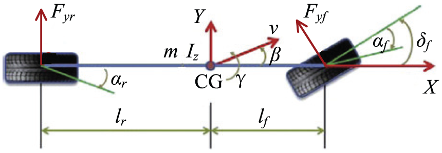
A 2-degree-of-freedom (2-DOF) bicycle model in the yaw plane is adopted for vehicle dynamics, as shown in Figure 6. In the model, vehicle lateral and yaw motions are mainly considered, ignoring the longitudinal, vertical, roll, and pitch motions. The vehicle has the mass m, moment of inertia Iz, sideslip angle β, yaw rate γ, and velocity v at the center of gravity (CG). lf and lr are the distances from the CG to the front and rear axles, respectively. δf is the front wheel steering angle. Fyf and Fyr are the tire lateral forces of the front and rear wheels, respectively. αf and αr are the tire slip angles of the front and rear wheels, respectively. The vehicle motions are modeled as

where vx is the longitudinal velocity that is equal to v.cos β.
Bicycle model for vehicle dynamics.
Given the assumption that the vehicle lateral acceleration is less than 0.4g (acceleration of gravity), the tire lateral force can be modeled in linear form 23


where Cf and Cr are the tire cornering stiffness of the front and rear wheels, respectively. αf and αr can be expressed as


Steering resistance
When the driver steers, the moments generated between the tires and ground are delivered to the driver through the ECHPS system and act as steering resistance. The steering resistance mainly consists of two moments, namely, the self-aligning moment and the moment by king pin inclination. 24 Therefore, the steering resistance can be approximated by

where r is the tire radius. λ1 denotes the caster angle and tp represents the pneumatic trail. Fz is the normal force. λ2 represents the king pin offset at the ground and λ3 denotes the king pin inclination.
Controller design
Problem formulation
Select the state variables as

where
For system (23), the control objective is to design an adaptive feedback control u such that the system output y = x1 tracks the desired valve spool displacement x1d under parameter uncertainties and external disturbances.
The following assumptions are required:
Assumption 1. All state variables of system (23) are measurable.
Assumption 2. The disturbance d is assumed to be bounded by a known positive constant.
Assumption 3. The reference trajectory vector
Adaptive DSC scheme
The adaptive DSC scheme consists of three steps:
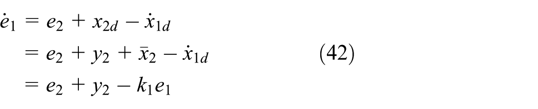
Step 1. Define the first surface error as

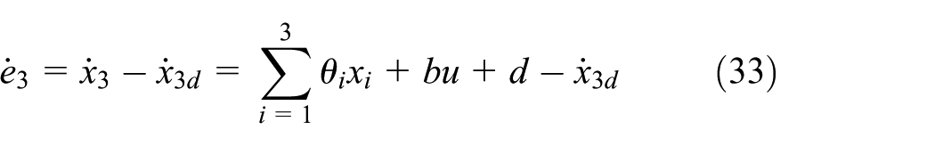
From system (23), we obtain

Choose the virtual control function

where k1 is a positive design parameter.
Let

Step 2. Define the second surface error as

According to system (23), we obtain

Choose the virtual control function

where k2 is a positive design parameter.
Let

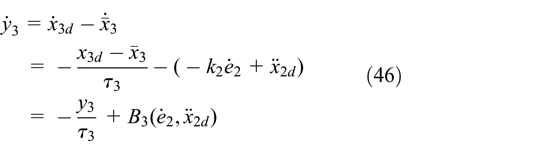
Step 3. Define the third surface error as

Considering system (23), we obtain
Define

where k3 is a positive design parameter, xd is a state variable, and
The adaptation laws of


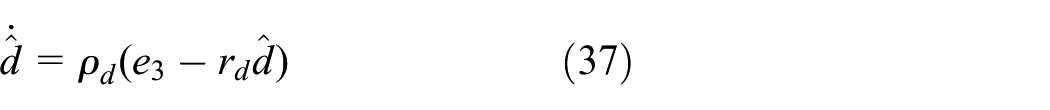
where ρ1, ρ2, ρ3, ρb, ρd, r1, r2, r3, rb, and rd are design parameters.
Stability analysis
The stability analysis of the closed-loop control system is conducted via Lyapunov synthesis.
From equations (27) and (31), the boundary layer errors are defined as

The estimate errors are given as


Considering equations (25) and (26), (28)–(30), (32)–(34), and (38)–(41), the derivatives of the surface errors can be deduced as


From equations (26), (27), (30), (31), and (38), the derivatives of the boundary layer errors can be obtained as

where
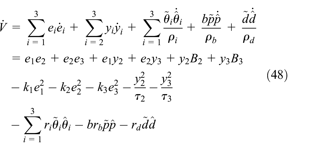
Define the Lyapunov function candidate as

Invoking equations (35)–(37) and (39)–(46), the derivative of V is given by
Employing the following inequalities

The derivative of V can be rewritten as

Let
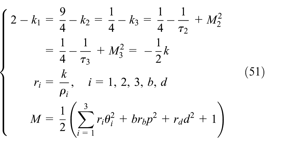
where k is a positive design parameter.
Substituting equation (51) into equation (50), we obtain

Integrating equation (52) over [0, t], we have

Therefore, it is concluded that the closed-loop control system is semi-globally uniformly ultimately bounded.
Simulation
To verify the effectiveness of the ECHPS system, numerical simulations of vehicle handling and stability test are conducted in MATLAB Simulink® environment. Table 3 lists the major parameters used in the numerical simulations.
Simulation parameters.

CG: center of gravity.
The simulation of lemniscate test is performed to check low-speed steering portability. In the lemniscate test, the vehicle moves with a constant speed of 10 km/h. The type of steering wheel angle input is sinusoidal, with a frequency of 0.02 Hz and an amplitude around 800°. Figure 7 shows the curve of steering wheel torque versus steering wheel angle in the lemniscate simulation. For ease of comparison, the steering wheel torque indices using the HPS and ECHPS systems in the lemniscate simulation are listed in Table 4. As can be seen in Table 4, the peak value of steering wheel torque using the ECHPS system is 5.32 N m, which increases by 6.83% compared with 4.98 N m using the HPS system. Moreover, the standard deviation of steering wheel torque using the ECHPS system is 3.08, which increases by 5.48% compared with 2.92 using the HPS system. In conclusion, the ECHPS system achieves nearly the same level of steering portability performance as the HPS system.

Steering wheel torque versus steering wheel angle in lemniscate simulation.
Steering wheel torque indices in lemniscate simulation.

HPS: hydraulic power steering; ECHPS: electronically controlled hydraulic power steering.
The simulation of on-center handling test is conducted to evaluate high-speed steering feel. The on-center handling test simulates the situation when driving a vehicle on a highway under low lateral acceleration without road or wind disturbances. In the test, the vehicle moves at a high speed of 80 km/h, and the steering wheel angle input is sinusoidal with a frequency of 0.2 Hz and a bounded amplitude to ensure the vehicle lateral acceleration under 0.2g. The curve of steering wheel torque versus lateral acceleration in the on-center handling simulation is shown in Figure 8. Table 5 lists the comparison of steering wheel torque gradient at lateral acceleration of 0g, which is an important index to evaluate steering feel. As can be seen in Table 5, the steering wheel torque gradient using the ECHPS system is 30.1 N m/g, which increases by 80.2% compared with 16.7 N m/g using the HPS system. It is concluded that the ECHPS system can significantly improve high-speed steering feel compared with the HPS system.

Steering wheel torque versus lateral acceleration in on-center handling simulation.
Steering wheel torque gradient in on-center handling simulation.

HPS: hydraulic power steering; ECHPS: electronically controlled hydraulic power steering.
Field test
To implement the adaptive DSC scheme, a rapid control prototyping (RCP) system is developed as illustrated in Figure 9. The developed RCP system consists of the MATLAB Simulink for control system modeling, the dSPACE MicroAutoBox as virtual controller for real-time simulation, the dSPACE RapidPro as power drive unit for actuating the EHPV, the linear displacement sensor for measuring valve spool displacement, and the EHPV as controlled plant. Moreover, Figure 10 shows the integration of the EHPV and recirculating ball steering gear.

Rapid control prototyping system.

Integration of EHPV and recirculating ball steering gear.
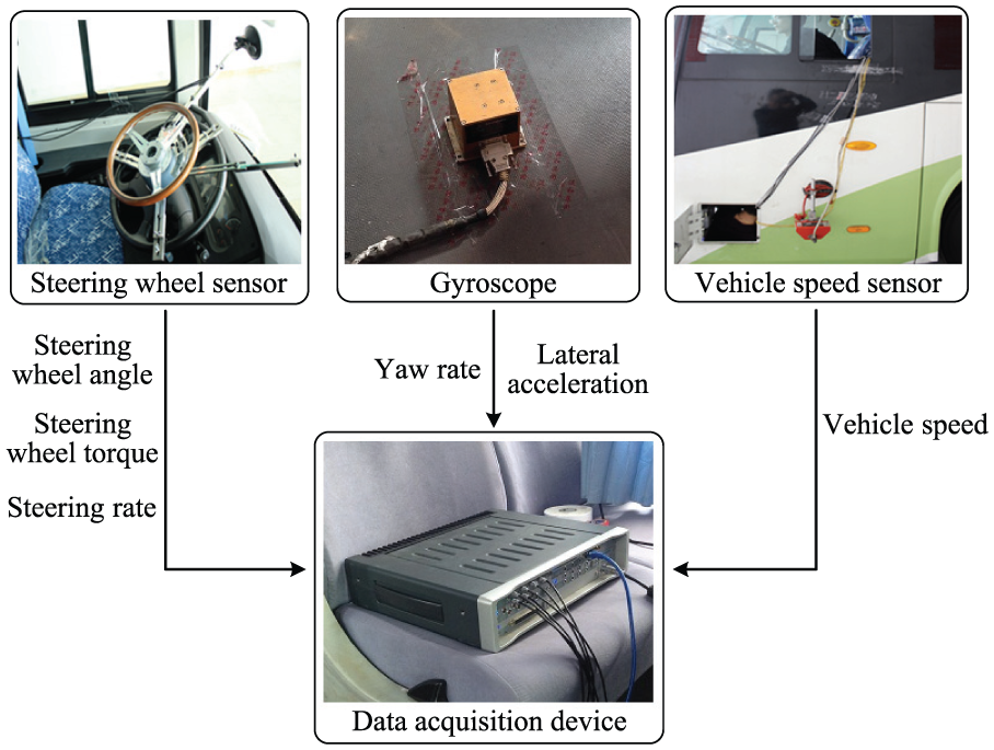
The test vehicle and measuring instruments are shown in Figures 11 and 12, respectively. The test vehicle is SLK6118 bus manufactured by Shanghai Shenlong Bus Company Limited. The measuring instruments include a steering wheel sensor, a gyroscope, a vehicle speed sensor, and an LMS data acquisition device. The steering wheel sensor measures steering wheel angle, steering wheel torque, and steering rate. The gyroscope provides signals of vehicle yaw rate and lateral acceleration, and the vehicle speed sensor measures vehicle speed. The LMS data acquisition device collects and monitors those signals.

Test vehicle.
Measuring instruments.
Figure 13 shows the tracking of valve spool displacement for desired value of 1.5 mm in simulation and experiment. The external disturbances in simulation is set to be 100(1 + sin 10πt) N. As shown in Figure 13, the tracking of valve spool displacement in simulation exhibits an overshoot of 0.6% and the settling time is 0.42 s. Moreover, the valve spool displacement in experiment tracks the desired value with acceptable overshoot of 8.3% and the settling time is 0.7 s, which is basically consistent with that in simulation. It can be seen that the adaptive DSC scheme can realize accurate tracking of valve spool displacement.

Tracking of valve spool displacement.
Field tests are performed to validate the applicability of the ECHPS system. The lemniscate test is conducted to check low-speed steering portability. Figure 14 shows the curve of steering wheel torque versus steering wheel angle in the lemniscate test. Table 6 lists the steering wheel torque indices using the HPS and ECHPS systems in the lemniscate test. As can be seen in Table 6, the peak value of steering wheel torque using the ECHPS system is 5.04 N m, which increases by 4.78% compared with 4.81 N m using the HPS system. The standard deviation of steering wheel torque using the ECHPS system is 2.90, which increases by 4.69% compared with 2.77 using the HPS system. In conclusion, the ECHPS system maintains the similar performance of low-speed steering portability as the HPS system. Moreover, it should be noted that the differences between simulation and experimental results are all within 10%, which indicates the consistency between numerical simulations and field tests.

Steering wheel torque versus steering wheel angle in lemniscate test.
Steering wheel torque indices in lemniscate test.

HPS: hydraulic power steering; ECHPS: electronically controlled hydraulic power steering.
The on-center handling test is performed to evaluate high-speed steering feel. The curve of steering wheel torque versus lateral acceleration in the on-center handling test is shown in Figure 15. Table 7 lists the comparison of steering wheel torque gradient at lateral acceleration of 0g. As can be seen in Table 7, the steering wheel torque gradient using the ECHPS system is 28.9 N m/g, which increases by 80.6% compared with 16 N m/g using the HPS system. It is concluded that the ECHPS system can significantly improve high-speed steering feel compared with the HPS system.

Steering wheel torque versus lateral acceleration in on-center handling test.
Steering wheel torque gradient in on-center handling test.

HPS: hydraulic power steering; ECHPS: electronically controlled hydraulic power steering.
Conclusion
This article has presented an analysis of the ECHPS system that can realize variable assistance characteristics and improve high-speed steering feel for heavy vehicles. A system description is given and mathematical modeling of the ECHPS system, vehicle, and steering resistance is conducted. An adaptive DSC scheme is proposed for the EHPV to realize accurate tracking of valve spool displacement under parameter uncertainty and external disturbance. Numerical simulations and field tests are performed to validate the effectiveness and applicability of the ECHPS system. The simulation and experimental results are consistent, which show that the ECHPS system can significantly improve high-speed steering feel compared with the HPS system while maintaining the similar performance of low-speed steering portability.
Footnotes
Academic Editor: Francesco Mass
Declaration of conflicting interests
The author(s) declared no potential conflicts of interest with respect to the research, authorship, and/or publication of this article.
Funding
The author(s) disclosed receipt of the following financial support for the research, authorship, and/or publication of this article: This work was supported by the National Natural Science Foundation of China (No. 51275211) and the Special Fund of Jiangsu Province for the Transformation of Scientific and Technological Achievements (No. BR2015168).