
Abstract
Numerical analysis is employed to investigate the influence of parting surface and combined thermal factor (rotation) on deformation of split mechanical seal. Parting surface takes little effect on the temperature distribution, verified by comparison experiment. Shaft rotation speed does not much affect the radial temperature gradient of the seal end faces but can raise the temperature when being increased. The simulated model turns to a drum, with the parting surfaces, close to the primary sealing interface presenting a convergent taper, becoming open-shaped. Increasing rotation dramatically intensifies the seal end face deformation of both split stationary and rotating seal rings and slightly increases the convergent taper size of the primary sealing interface. However, it takes little effect on the parting surface deformation. Compared with integral mechanical seal, parting surfaces distinctly reduce the primary sealing interface cone as well as the seal end face deformation of both split seal rings.
Introduction
Mechanical seals have been widely applied in various occasions, such us marine, aeronautical, electric, and petrochemical industries. Friction and wear happen between seal end faces of rotating and stationary rings during operation or when working conditions change. The induced failure, such as leakage and end of operational life, can lead to a long-term shutdown of machinery to repair or replace the damaged mechanical seals. For integral mechanical seals, we have to remove the damaged ones after taking down all impeding parts over the end of shaft and then reinstall with the replaced seals. Such procedure could be both costly and arduous, especially for large equipment. 1 Fortunately, split mechanical seals with parts cut into halves solve the above problems.2–4 Several studies5–7 show that split mechanical seals also have obvious advantages over packing seals, including long life (usually four times longer than packing seals), economic material usage, less pollution, faster maintenance, no requirement for adjustment, no scratch on shaft and sleeve, and higher efficiency due to low friction. The basic working principle of split mechanical seals is almost the same as conventional integral ones, while the corresponding parting surfaces are distinct. Current researches on split mechanical seals are mainly restricted to their geometry, proving the design feasibility with reasonable methods to connect the parting surfaces of all split rings.8–12 However, split mechanical seals have not been widely used because parting surfaces exist. Not only do they break the geometric continuity of integral seal rings, yielding axial leaking paths but also change the deforming form of the rings. Once deformation happens when thermal loads, external forces, and constraints are applied on seal, it will influence the leakage rate, frictional wear between seal end faces, and connecting tightness of parting surfaces. Therefore, learning the deformation law of split mechanical seal is necessary. Generally, there are two thermal impact factors that largely affect the thermal gradients. One of them is the convective heat transfer coefficient on wetted surface of seal ring and the other is the frictional heat generated on sealing interface between two seal end faces. 13 Both of them are significantly correlated with shaft rotation.14,15 However, the former reduces the mechanical seal temperature, but the latter plays an adverse role. It is appropriate to investigate the influence of the combined thermal factor on split mechanical seal deformation instead of considering the two factors separately.
This study estimates convective heat transfer coefficients and frictional heat by expressions16–20 and reasonably presets external forces and constraints. Based on these, simulations for the temperature distribution and thermomechanical coupled deformation of both split and integral mechanical seal models are conducted by ANSYS Workbench. Numerical analysis of the simulation results under different shaft rotational speeds is performed in order to obtain the combined impacts of the convection and frictional heat on the deformation of split mechanical seal. Comparative analysis between the results of split and integral mechanical seals is presented to illustrate the influences of parting surface, and experiments are employed to verify these influences. This research is hopeful to provide theoretical guidance for the design of split mechanical seals.
Analytical model of a split mechanical seal
Figure 1 presents a half-section view of a split mechanical seal. Sealed medium flows into the chamber surrounded by rotating ring, stationary ring, hoops, shaft sleeve, and shell, exchanging heat with seal components. Rotating ring rotates with the shaft sleeve fixed on the shaft, and stationary ring is fixed in the shell. Primary sealing interface is formed by contact of the seal end faces of rotating and stationary rings. Two half rings of each seal ring contact with each other as the secondary sealing interfaces. The split mechanical seal rings and elastic elements make up a sealing system to prevent the fluid from leaking into external environment.

Half-section view of the split mechanical seal.
Geometric model
In this study, the effect of O-ring is approximately replaced by constraints; thus, O-ring model is omitted. Besides, boss, gaskets, and other parts are neglected, and the springs and hoops are replaced by spring and clamping pressures, respectively. Furthermore, we analyze the contact pair of rotating and stationary seal rings rather than simulate them separately, which does not involve the calculation of heat partition. Therefore, the geometric model serving for the object of this study includes three-dimensional stationary half rings and rotating half rings assembled. A two-dimensional diagram is shown in Figure 2.

Geometric model and boundary conditions of the split rotating and stationary rings.
Boundary conditions
Thermal boundary conditions include medium temperature, convection, and heat flux. The known medium temperature acts on the wetted surfaces of seal rings. The computational boundaries of interest for convective heat transfer coefficients are shown in Figure 2. In this figure, ab, cd, ef, and gh are the wetted cylindrical surfaces of rotating ring; ij, kl, and mn are of stationary ring; and bc, fg, hi, and jk are the wetted vertical faces of both seal rings. Other surfaces surrounded by air are considered to be natural convection with air, and the convective heat transfer on each wetted surface is assumed to be uniform. Here, although the oblique surfaces of the trapezoid ring groove contact with hoops, each groove has a large clearance filled with air at the bottom (shown in Figure 1), the size of hoops are large enough, and its conductivity of the stainless material is not good; therefore, the oblique surfaces are also assumed to be adiabatic. With the hypothesis of no effect of parting surfaces on the convection, the existing expressions,17,18 for calculating the convective heat transfer coefficients of integral seal ring, are applied on the present split seal. The heat flux generated on the primary sealing interface is also calculated by empirical expression.16,19,20 The thermal physical properties of seal rings and sealed medium are regarded as constant. Then, the properties of seal rings and medium are listed in Table 1.
The properties of seal rings and sealed medium.

Ignoring the bulk force and inertia force of seal rings, force boundary conditions include medium, spring, and clamping pressures, as shown in Figure 2. p1 (0.5 MPa) refers to medium pressure, and p2 (0.45 MPa) and p3 (0.5 MPa) are, respectively, the clamping pressures on the stationary and rotating rings, selected according to the elastic modulus of the former less than the latter. ps (0.2 MPa) represents spring pressure. The pressures are hypothesized to uniformly act on their corresponding surfaces. Additionally, there should be no axial (X-direction) displacement of the red boundary and no radial and tangential displacement of the blue boundaries, as shown in Figure 2.
Basic settings and loadings
Frictional heat is supposed to transfer through seal rings without considering heat dissipation by fluid leakage and the heat emission by radiation. 21 Deformation is investigated by thermal stress analysis, a coupled method of steady-state thermal dynamic and structural static analysis.
Primary sealing interface is set as the frictional contact, and parting surface contacts are frictionless. Friction coefficient is reasonable to be treated as a constant of 0.07, 16 and it also takes little effect on convective heat transfer. 22 The heat transfer coefficients are applied on each wetted surface of seal rings, and other surfaces are considered to be adiabatic. Then, hex-dominant method is chosen to mesh the model. Body element size of seal rings is 2 mm, and seal end faces and parting surfaces are refined with magnitude of 2. As a consequence, element number is 123107, and node number is 191379. At present, loading and constraint settings can be processed, and the details are shown in Figure 3, where the displacement X = 0 limits the axial displacement of the specific surface (red boundary), and the cylindrical support makes the radial and tangential displacement of the blue boundaries fixed except the free axial.

Temperature distribution on the seal end faces of stationary rings.
Theoretical basis
Heat conduction
For split mechanical seal operating in steady state, heat conduction equation in polar coordinates is as follows

Heat transfer
The frictional heat between the seal end faces is mainly dissipated by convection effect of fluid flow within the chamber and by conduction to adjacent components. Therefore, the convective heat transfer coefficient is one of the main factors affecting the temperature gradient, as mentioned above. These coefficients are calculated by empirical expressions as follows.
For the boundaries ab, cd, ef, and gh17,18
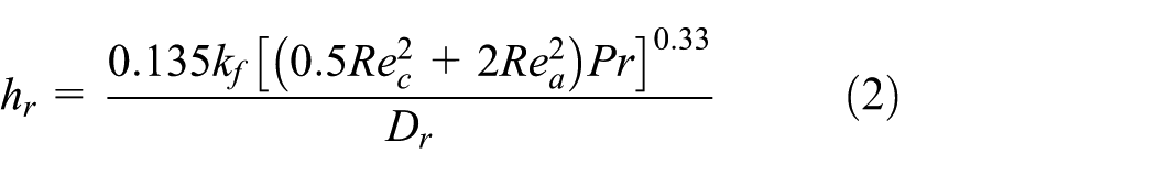
Here, kf is the thermal conductivity coefficient of sealed medium, Pr refers to Prandtl number of sealed medium, and Dr is the periphery equivalent diameter of rotating ring.
For the boundaries ij, kl, and mn18,23

where 2 is preferable to ε1, Ss represents clearance between the peripheral cylinder surface of stationary ring and inner cylinder surface of shell, and Re = 2VSs/v, where V refers to axial velocity of the sealed medium of stationary ring.
For the boundaries bc, fg, hi, and jk 18

In this equation, L is the characteristic length of wetted vertical faces of seal rings, and Rev = VvSv/v, where Vv is the circumferential velocity of medium in the clearance between two adjacent wetted vertical faces of seal rings, and Sv refers to clearance between two adjacent wetted vertical faces of seal rings. At this point, these convective heat transfer coefficients will be determined if the shaft rotation is given.
Heat generation
For simplified calculation, frictional heat is taken to be uniformly distributed on the primary sealing interface. Also, the frictional heat totally comes from contact friction by neglecting the water film between seal end faces. Then, the contact friction is solved by equation (5)16,19,20

where f represents the frictional coefficient, suggested to be a constant. pc is the specific pressure of primary sealing interface, which is considered to be constant and given as 0.15 MPa in the present numerical analysis.
Deformation
Split mechanical seal deformation is the sum of mechanical deformation and thermal deformation. 24 Considering the nonaxisymmetrical split cylindrical rings, the deformation should be solved as a three-dimensional problem. Based on thermoelasticity of homogeneous isotropic solid, 25 equilibrium equations of deformation are as follows

where σ represents node stress, and F is the external force. The stresses and strains are expressed by Hooke’s law as follows

where

In equations (7) and (8), i, j, k = 1, 2, 3.
Results and discussions
Numerical simulation of the thermomechanical deformation under shaft speeds of 2440, 2940, 3440, and 3940 r/min are performed to get general results. Meanwhile, an integral mechanical seal model is analyzed to investigate the effect of parting surfaces. Numerical results of the temperature distribution of the rotating and stationary seal end faces and parting surfaces are depicted in Figures 3–5, and the results of the thermomechanical coupled deformation are depicted in Figures 6–12.

Temperature distribution on the seal end faces of rotating rings.
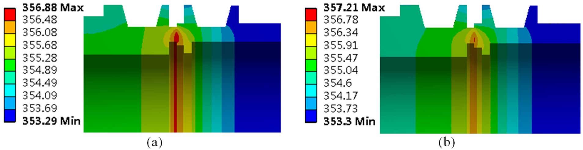
Temperature distribution of seal rings in the axial direction (K): (a) split rings and (b) integral rings.
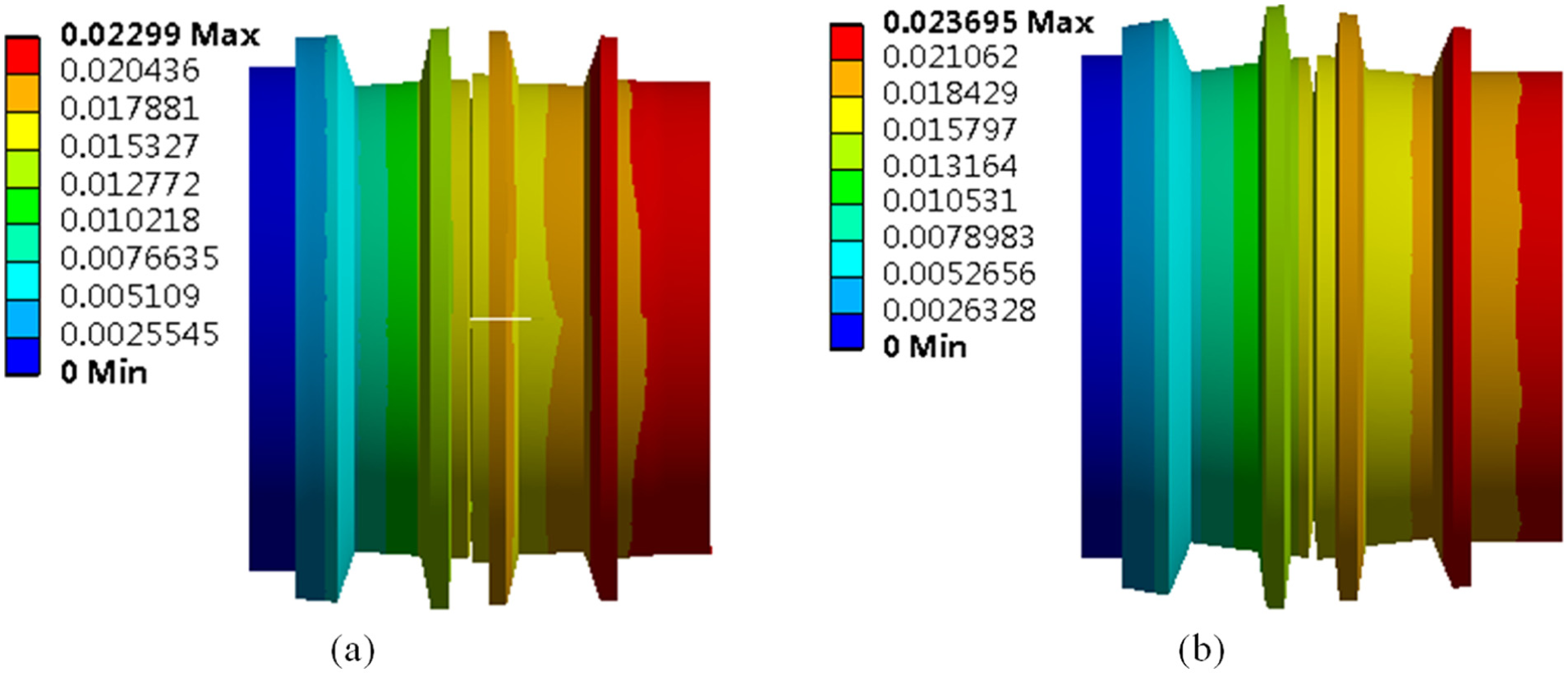
Deformation of seal rings (mm): (a) split rings and (b) integral rings.

Definition of the deformation direction of seal end faces.

Deformation of the seal end faces at different rotation speeds: (a) Deformation under 2440rpm, (b) Deformation under 2940rpm, (c) Deformation under 3440rpm, and (d) Deformation under 3940rpm.

Z-directional deformation of stationary parting surface along the radial direction.

Z-directional deformation of stationary parting surface along the axial direction.

Z-directional deformation of rotating parting surface along the radial direction.

Z-directional deformation of rotating parting surface along the axial direction.
Temperature distribution under different rotations
In Figure 3, temperature results of stationary seal end face are plotted against the dimensionless radius, (r − rsi)/(rso − rsi). r, rsi, and rso are the arbitrary, inner, and outer radii of the stationary seal end face, respectively. The sampling nodes for collecting temperature results are selected along path 1 (see in Figure 2). The reason of such selection is that logic suggests that the apparent differences compared with integral rings should be at parting surfaces. This figure obviously shows the temperature rises with increasing rotation speed, which coincides with Ayadi et al.’s 26 numerical and experimental results. At four rotations, the temperature curves of the integral and split seal rings fit well and present the same trends. They climb from inside in the radial direction, reach the highest points at radial ratio of 0.25 near the inner diameter, and then decrease till the outer diameter, with the maximal temperature differences of about 1.5 K in the radial direction. The radial temperature difference is caused by good convection to sealed medium flowing over peripheral cylindrical surfaces, but poor convection between inner surfaces and air. While the similar difference values are resulting from the convection on stationary ring almost being unaffected by the shaft rotation.
In Figure 4, the parameters, r, rri, and rro, of the dimensionless radius, (r − rri)/(rro − rri), represent the arbitrary, inner, and outer radii of the rotating seal end face, respectively. The sampling nodes for temperature are along path 2, as marked in Figure 2. It shows that the faster the shaft rotates, the higher the temperature is, for both integral and split rotating rings. The temperature curves at four rotations are extremely similar. They climb in the radial direction to the peak close to radial ratio of 0.33 instead of 0.25 for the split stationary ring, because split rotating ring has wider seal end face, leading to poor heat emission. They then drop visibly after these points to the nadirs at the outer diameter due to radial thermal gradient. The maximal temperature difference in the radial direction becomes bigger with increasing rotation, attributed to more heat dissipation with the enhanced convection when rotation is increased. For integral rotating ring, the temperature on seal end face presents the extremely similar characteristics as the split one, which indicates that the parting surface indistinctively affects the temperature distribution of split mechanical seal.
In Figure 5, the temperature of axial cross section axially reduces from the primary sealing interface to both sides, appearing as a parabolic distribution. The difference of the maximum is less than 0.5 K, which indicates that the parting surfaces can slightly reduce the body temperature of seal rings because heat dissipating area are added by parting surfaces. Four cases of different rotations have extremely similar trends as well as the tiny temperature difference under each case; thus, here only the case of 2940 r/min is given.
Thermomechanical coupled deformation under different rotations
Figure 6(a) and (b) shows that the solved models become similar drum-shaped under the same operating condition due to axial and radial positive deformations of seal end faces. Meanwhile, the figures show that deformations of the two models mainly occur in the axial direction, and their close values indicate that parting surface takes little effect on the axial deformation. Figure 7 is the enlarged scale of deformation with undeformed frame. The deformation directions of seal end faces are defined according to Moaveni, 24 as shown in Figure 7, while other directions are according to the Cartesian coordinate, as shown in Figure 2, and so-called axial direction refers to X-direction. From Figure 6, we can see that two positive deformations of stationary seal end face and rotating seal end face form a convergent gap due to the convection with outside sealed medium. Additionally, the parting surface near the primary sealing interface radially deforms into an open shape, resulting from the higher temperature inside producing larger internal deformation. For further details, deformation under four different rotational speeds is simulated, and the results are shown in Figures 8–12.
We select deformation nodes along paths 1–4. Path 1 is for the primary sealing interface deformation and stationary parting surface Z-directional deformation along the radial direction. Path 2 is for the rotating parting surface Z-directional deformation along the radial direction. Path 3 and 4 are, respectively, for the Z-directional deformation of the stator and rotor along the axial direction, as shown in Figure 2.
Axial deformation curves of seal end faces at four rotational speeds are plotted in Figure 8. The curves of stationary ring generally indicate a negative slope along the radial direction in four cases, because the radial temperature gradient produces more inside deformation, further bringing out the positive torsion. Because of facing against the stationary seal end face, the deformation of rotating seal end face, however, linearly increases. Moreover, it is obvious that the split seal deforms less than the integral seal at all rotational speeds because the parting surface can slightly reduce the body temperature of split seal compared to integral one under the same boundary conditions, which is obtained in the temperature distribution section. When carefully analyzing the data on the vertical coordinates, we find the maximal width of open mouth at the outer diameter of split seal increases with rising rotation, with 2.09 µm at 2440 r/min, 2.13 µm at 2940 r/min, 2.15 µm at 3440 r/min, and 2.19 µm at 3940 r/min. Ayadi et al. 26 got the same trend. However, the primary sealing gap insensitively changes with given shaft rotations. The reason is that the almost constant temperature gradient on split stationary seal end face makes its positive deformation keeping steady; meanwhile, the increasing temperature gradient on split rotating seal end face leads to its positive deformation increasing but roughly resulting from the large elastic modulus of the rotating ring.
Figure 9 depicts the Z-directional deformation curves of selected nodes along path 1, showing the Z-directional deformation of stationary parting surface along the radial direction. Here, it should be noted that only one half ring deformation is presented considering the symmetry. These curves of each corresponding parting surface are similar, presenting radially open shapes with quadratic edges from radial ratio of 0 to 1 attributed to radial temperature gradient. When reaching radial ratio of 0.5, the open shape size remains steady. Additionally, with rising rotational speed, the open shape increases until 2940, then almost keeping a constant with the largest open mouth of 0.34 µm at the outer diameter.
The Z-directional deformations of the stationary parting surface at four rotational speeds are drawn in Figure 10 showing similar trends. It can be figured out that the gap between two contact stationary parting surfaces axially decreases from the primary sealing interface and turns to less than 0.025 nm after −2.5 mm position. Also, the maximum gap at 0 position (the primary sealing interface) is no more than 0.27 µm, accounting for good contacting tightness of stationary parting surfaces. It is clear that the largest changes in temperature occur close to the primary sealing interface with frictional heat, and the temperature gradient axially decreases, which causes the above axial deformation of parting surface.
Figure 11 provides the Z-directional deformation of the rotating parting surface along the radial direction. It presents a radial open gap, which linearly increases from the ratio of 0 to 1, attributed to more expansion inside resulting from intense convection outside. The conditions at four rotation speeds have almost the same curves, indicating the insignificant effect of rotation speed on this deformation. From these curves, we find the largest open mouths at the outer diameter of about 2.72 µm and the smallest at the inner diameter of about 2.1 µm. This large gap will lead to serious leakage and therefore needs to be reduced. Otherwise, the two deformation values of split rotating ring are, respectively, larger than those of split stationary one of around 0.34 and 0 µm, which is possibly attributed to their different materials, temperature distribution, 27 and geometric structure, or maybe the insufficient clamping pressure is the main reason. For making sure, the effect of clamping pressure is also investigated, which is shown below.
The Z-directional deformation of the rotating parting surface along the axial direction can be seen from Figure 12. It presents similar results under four conditions. The gap between the two parting surfaces diminishes axially from 0 position, becomes nil after 11 mm position, and generates a maximal open mouth of 2.4 µm at 0 position. Same with the axial deformation of the stationary secondary sealing interface, this phenomenon can be explained by considering the axial temperature gradient.
Further investigation
This section is to investigate the effect of clamping pressure on thermomechanical coupled deformation to verify the speculation of the reason for the rotating parting surface deformation above. Clamping pressure of 0.5, 0.6, and 0.7 MPa for rotating ring and with the determined conditions of 0.45 MPa clamping pressure for split stationary ring, 3440 r/min shaft rotation, and 0.5 MPa media pressure are simulated. The results are shown in Figure 13.
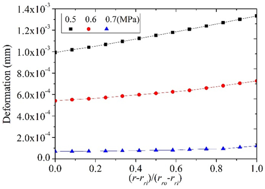
Z-directional deformation of rotating parting surface along the radial direction under different clamping pressures.
Figure 13 shows that the Z-directional deformations of parting surfaces of split rotating seal rings affected by four groups of different clamping pressures are plotted against dimensional radius. It can be seen that the radial parting surface gap dramatically decreases from the maximum of 2.72 to 0.24 µm when increasing the clamping pressure from 0 to 0.7 MPa. This accounts that clamping pressure does much affect the deformation of rotating parting surfaces, and the speculation above is reasonable. Furthermore, it can be inferred that increasing clamping pressure could effectively keep good contact of both stationary and rotating parting surfaces. Note that all results are based on each maximal internal stress being in safe limit.
Experimental verification
Experimental apparatus
Experiments are conducted to verify the effect of split seal ring parting surfaces on seal end face temperature. The apparatus shown in Figure 14 is for testing mechanical seal performance, including 1: motor, 2: coupling, 3: speed torque sensor, 4: bearing support, 5: bearing, 6: shaft, 7: seal chamber, 8: rotating ring, 9: stationary ring, and 10: leakage chamber. Figure 15 shows the experimental control system, where the medium temperature in surge tank is tested by heating rod and temperature controller, keeping the temperature steady by cooling system, and measured by temperature sensor 1. In this cooling system, the heated medium in the seal chamber is pumped into the surge tank, and then back to the chamber; meanwhile, the cooling water from reservoir continuously flows around the medium coil pipe to take away heat of the medium and flows back to the reservoir. Medium pressure is controlled by nitrogen container and measured by pressure sensor 2. The little leakage of nitrogen relative to the volume of the container is ignored, and the outlet pressure of the reducing value is constant; thus, the medium pressure is kept steady. Rotation speed is decided by HLP-NV frequency transformer and measured by revolution speed sensor 3. Two mechanical seal friction pairs can be, respectively, installed on the shaft at the two ends of the seal chamber, and the temperature of two stationary seal rings is measured by temperature sensors 4 and 5, respectively, then acquired by data acquisition box, and finally shown in the PC.

Mechanical seal performance testing apparatus.
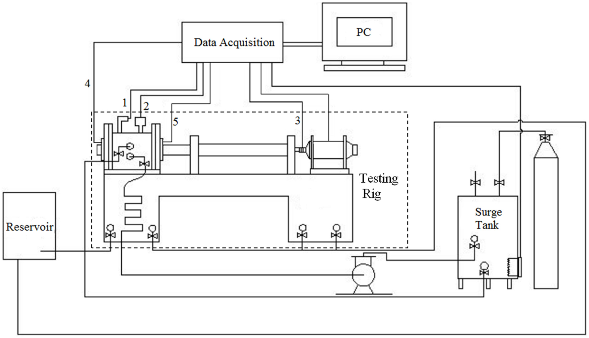
Schematic representation of mechanical seal experimental control system.
Figure 16 is a center cross-sectional view of the mechanical seal performance testing apparatus for an installation and accommodation of two same mechanical seals (respectively, on the left and right sides of the shaft) under test. Due to the shaft sleeve 2 on the main shaft 1 without axial positioning, the shaft sleeve 2 is rotated to drive the two nuts 4 which are screwed and jointed with the shaft sleeve 2 to move back-to-back; the rotating ring seats 5 of the two mechanical seals are driven to, respectively, press toward the rotating O-shaped circles 8 and the rotating rings 9 via the springs 6 and the support rings 7, when an initial position of a center cross section of the shaft sleeve 2 is not coincident with a center cross section of the working chamber 10, namely, when a distance between the initial position of the center cross section of the shaft sleeve 2 and an end face of a stationary ring 3 on one end cover is not equal to a distance between that of the shaft sleeve 2 and the stationary ring on the other end cover; one mechanical seal which first presses the stationary ring 3 pushes the shaft sleeve 2 to move toward the other mechanical seal till the rotating ring 9 and the stationary ring 3 of the other group of mechanical seal contact with each other; and then the end face–specific pressure of the two mechanical seals is increased simultaneously. Therefore, the shaft sleeve 2 is rotated for automatically centering and for allowing the two mechanical seals to obtain a same initial end face–specific pressure. The rotating O-shaped circle 8 between the support ring 5 and the rotating ring 9 ensures the sealing between the rotating ring and the shaft sleeve. 28

The center cross-sectional view of the mechanical seal performance testing apparatus.
Seal ring design
Two same mechanical seals except the parting surface feature are symmetrically installed at opposite ends of the seal chamber (Figure 15), but one is with split stationary ring and the other with both integral rings for comparison considering the same operating conditions. Rotating ring is SiC, and the stationary ring is M106 K. The split stationary ring segment and integral stationary ring are shown in Figure 17(a) and (b), respectively. Here, split stationary ring is made by breaking one integral stationary ring into two segments with natural fractures in order to assure no material wastage on parting surface, which makes the two segments fit into a complete circle. Five thermocouples holes are drilled through the stationary ring from back at the depth of 0.3 mm away from the primary sealing interface. Thermocouples are circumferentially distributed along 86 mm outer diameter of stationary ring and have diameter of 56, 64, 72, 78, and 82 mm for No. 1, No. 2, No. 3, No. 4, and No. 5, respectively (see Figure 18). It is 5° between the circumferential position of No. 5 and parting surface. Temperature sensors 4 and 5 shown in Figure 15 are, respectively, for split and integral stationary rings.

Stationary ring: (a) split ring segment and (b) integral ring.
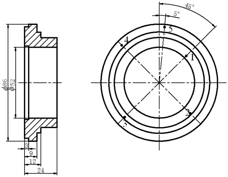
Drawing of stationary ring.
Experimental procedure
Medium temperature, medium pressure, and rotation speed, respectively, are 80°C, 0.5 MPa, and 2440 r/min for this experiment. Spring pressure of 0.15 MPa was exerted on the primary sealing interface. Finally, associated with medium pressure, specific pressure of 0.3 MPa was generated on the primary sealing interface. It took 30 min to run-in, when the temperature of stationary ring became almost steady, and all temperature data were collected by collection card for temperature in data acquisition box (shown in Figure 14) and output to the PC. The compared results are shown in Figure 19.

Comparison of experimental results.
Experimental results
Figure 17 shows similar trend with the numerical simulated results shown in Figure 3, and also, the highest temperature seemingly appears near the radial ratio of 0.25 despite different models used. Besides, it obviously shows that the temperature of split stationary ring is a little lower than the integral one, verifying parting surface can exactly slightly reduce ring body temperature and agree with the numerical simulated results shown in Figure 5. The temperature is much higher than the simulated one under 2440 r/min because the frictional area of the experimental model is much larger than the simulated one.
Conclusion
For the split mechanical seal with inward leakage simulated, the temperature on seal end faces of the split mechanical seal increases from the inner diameter but begins to decrease after reaching one point, the radial ratio of 0.25 for stationary ring and 0.33 for rotating ring. The lowest temperature of both seal rings is at the outer diameter. The axial temperature decreases from the primary sealing interface to both sides, similar to a parabolic distribution. Parting surface takes little effect on the temperature distribution through numerical and experimental comparisons with integral mechanical seal. Shaft rotation speed does not much affect the radial temperature gradient of the seal end faces but can make higher temperature when being increased. If the temperature of the primary sealing interface is so high that needs to be cooled, then the self-pumping structure could be applied on the split rotating ring, which can be cooled by itself without other auxiliary cooling systems. 29
When subjected to given constraints, thermal loads and external forces, the primary sealing interface appears a positive cone in the leakage direction. Meanwhile, the secondary sealing interfaces of both split stationary and rotating seal rings form open gaps near the primary sealing interface. In the radial direction, the open gaps of split mechanical seal rings is enlarged from inner to outer radius, presenting quadratic gap edges for the stationary ring and linear for the rotating ring. In the axial direction, they decrease from the primary sealing interface, close to zero after the axial length ratio of 0.1 for the stator and 0.42 for the rotor. However, the parting surface gaps can be dramatically reduced by increasing clamping pressure. For this present model, 0.5 MPa for split stationary ring and 0.7 MPa for the rotating one are optimal. Parting surface can distinctly reduce the seal end face deformation, especially for split rotating ring, and diminish the primary sealing interface cone. The increasing combined thermal factor, rotation, dramatically increases the seal end face deformation of both split seal rings and slightly enlarges the primary sealing interface cone but hardly influences the parting surface deformation. Therefore, it is meaningful to study split mechanical seal further not only for its convenient assembling and disassembling but also for its theoretical feasibility concluded by this research.
Footnotes
Academic Editor: Jose Ramon Serrano
Declaration of conflicting interests
The author(s) declared no potential conflicts of interest with respect to the research, authorship, and/or publication of this article.
Funding
The author(s) disclosed receipt of the following financial support for the research, authorship, and/or publication of this article: The study is supported by the project funded by the Priority Academic Program Development of Jiangsu Higher Education Institutions, the project of National Natural Science Foundation of China (nos 51375245 and 51505230), the project of Natural Science Foundation of Jiangsu Province (BK20130976), and Doctorate Fellowship Foundation of Nanjing Forestry University.