
Abstract
In this work, the residual stress state of a human common carotid artery is predicted using the so-called thermomechanical analogy approach. The purpose of the approach is to enable consistent mapping of residual stresses and the respective configuration from a circular arterial segment to a patient-specific arterial geometry. This is achieved by applying proper volumetric dilatations to the actual arterial stress-free in vivo geometry, which makes use of the analogy that states that the bending stresses can be obtained on an equivalent manner by applying proper thermal dilatations. The common carotid artery data are obtained in vivo from a healthy 28-year-old man using non-invasive methods. The predicted residual stresses of the common carotid artery are in good quantitative agreement with the data from prior work in this field. The approach is validated by predicting the common carotid artery zero-stress state configuration, where a sector-like (cut-open) state is obtained. With this approach, it is thus possible to predict the residual stresses as well as the configuration of patient-specific arterial geometry without the need to model its cut-open zero-stress configuration.
Keywords
Introduction
The mechanical environment and the properties of arteries play an important role in the origin and progression of vascular diseases. 1 Numerical simulations of arterial mechanical response can therefore help us to understand the role of the arterial in vivo mechanical response in vascular pathogenesis. Additionally, it can aid in the improvement of (non)surgical procedures and the development of prosthetic materials and tissue equivalents. 1 However, one of the major challenges in vascular biomechanics that has not yet been solved sufficiently is the prediction of a patient-specific arterial stress-free state (or any intermediate arterial stress state and its corresponding configuration).
Experimental observations show that the geometry of the arterial zero-stress state assumes a sector-like shape.2–4 This phenomenon is associated with the fact that the arterial unloaded state, that is, a state when the artery is removed from the body, is pre-stressed. It is believed that these stresses, known as residual stresses, homogenise the circumferential stress when the artery is under physiological pressure.5,6 Residual stresses can be measured experimentally with the so-called opening angle method, introduced by Chuong and Fung. 5 In the experiment, a longitudinal cut is performed on a dissected arterial ring. Because the ring is pre-stressed, it opens up, and the amount of the opening is then used as a measure of residual stress. For an in vivo assessment of residual stresses, an approach proposed by Takamizawa and Hayashi 7 is normally used. They assumed that the intraluminal distribution of circumferential stresses under a physiological loading condition is uniform, which can be achieved only with the existence of (bending) residual stresses. However, the approach, known as the uniform strain hypothesis, appears to be applicable only for idealised (circular) arterial rings 8 and can hardly be used for a complex three-dimensional (3D) arterial geometry.
Several approaches can be found in the literature for predicting the arterial residual stress state. Alastrué et al. 6 used a multiplicative split of the deformation gradient tensor into a non-compatible tensor, which takes into account the initial strain field, and an elastic compatible tensor, which results from the compatibility enforcement. The first is obtained from the opening angle experiment by computing the residual stress of a circular arterial ring, whereas the latter basically maps the obtained state onto an equilibrium state. In Polzer et al., 8 an algorithm is proposed that leads to the prediction of residual stresses through volumetric tissue growth. Residual strains are iteratively applied to an arterial configuration with the aim of satisfying the homogeneous stress hypothesis at the mean arterial pressure load. However, the arterial configuration used, based on which the residual stresses are applied to, needs to be initially given. Zhou and Lu 9 proposed an inverse elastostatic formulation approach to predict the open stress-free arterial configuration inversely. This is achieved by assuming that the in vivo arterial state is under a uniform homeostatic stress throughout the thickness of the entire arterial wall. The value of the applied stress is obtained by analysing a circular arterial segment and using the opening angle as a measure of residual stress. By solving an inverse boundary value problem, the open arterial configuration can then be predicted. Schröder and Brinkhues 10 analysed gradients of suitable invariant stress measures in the thickness direction of the arterial wall. By smoothing these gradients between the inner and outer margins of individual arterial layers using their volumetric mean values, the residual stresses are obtained. This is performed by dividing the artery into suitable radial sections on which the smoothing condition is enforced independently. Additionally, different growth theories have been introduced to predict how residual stresses develop over time and, also, at different length scales.11–13 However, they have been mostly presented by treating an idealised arterial ring.
In this work, the residual stress state of a human common carotid artery (CCA) is numerically predicted using the thermomechanical analogy (TMA) approach. The approach, which was recently proposed by the authors 14 and is, in this work, applied to model the response of a human CCA for the first time, predicts the arterial residual stress state by applying proper volumetric dilatations to the arterial in vivo stress-free configuration. The amount of dilatation required is obtained by characterising the mechanical response of an idealised (circular) arterial ring, and the opening angle method is used to quantify the residual stress. The CCA data are obtained from a 28-year-old healthy male using non-invasive methods. The mechanical response of the artery is, in this work, treated in a simplified manner as hyperelastic and isotropic. The approach is validated by comparing the predicted CCA residual stresses with the data of residual stresses available in the literature and by predicting the CCA cut-open zero-stress state.
The structure of this article is as follows. First, the TMA approach is presented in a general manner in order to highlight its main steps and their purposes. The experimental data and their acquisition are then briefly presented in section ‘Experimental data’. In section ‘Modelling the CCA mechanical response’, the TMA approach is then applied to the analysed CCA, whereas sections ‘Results and discussion’ and ‘Conclusion’ give the results and conclusions, respectively.
The general concept of using the TMA approach
Let us first present the general concept of the TMA approach using a case of treating a bended and axially stretched cantilever beam, presented in Figure 1(a). Although this example is in no direct relation with the problem of observing an arterial section per se, it will highlight all the key steps of the methodology in a somewhat simple and easy-to-understand example.
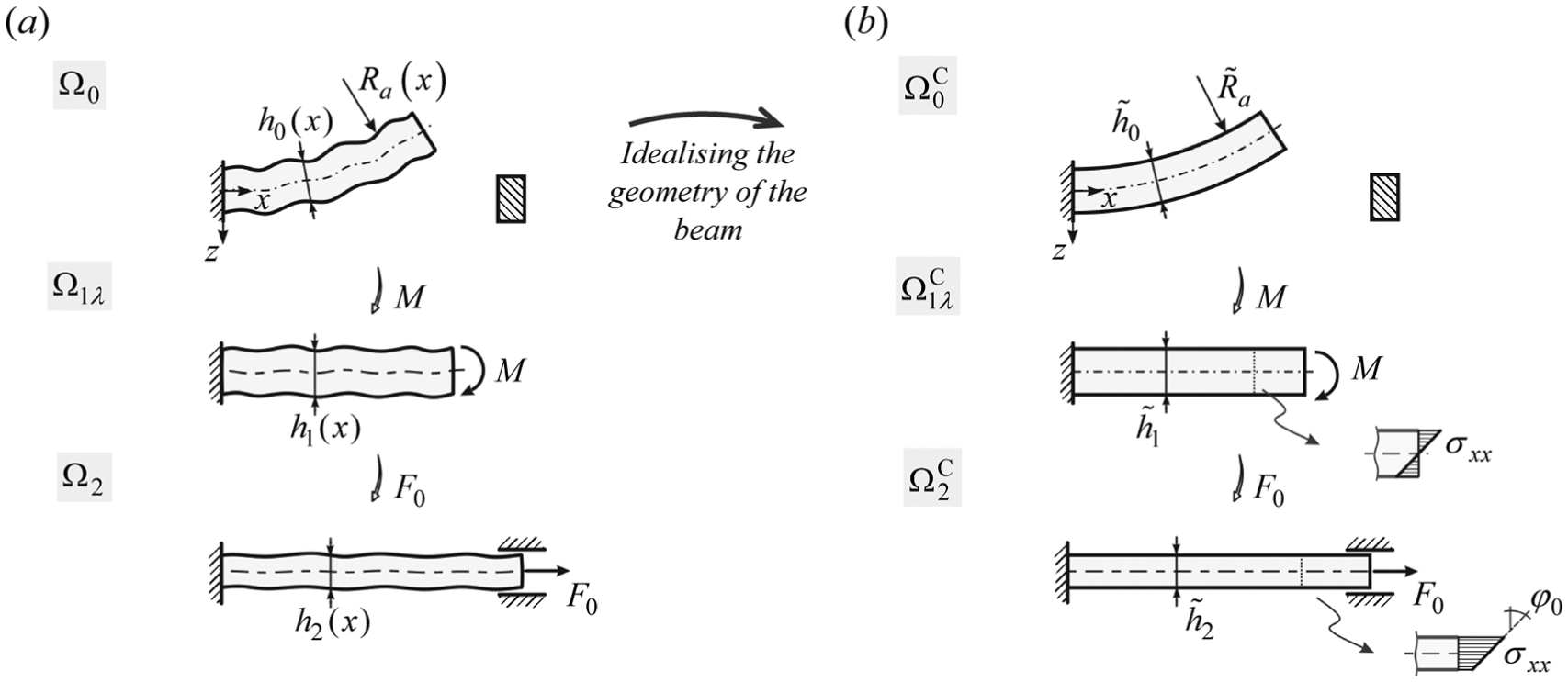
Bended and axially stretched beam example: (a) the observed problem and (b) beam with idealised geometry.
Additionally, this example demonstrates the purpose of using TMA more clearly. The general concept of applying TMA to treat an arterial segment is then presented in section ‘Applying the TMA approach to predict the mechanical response of an arterial segment’.
Bended and axially stretched beam example
We can observe the beam in Figure 1(a) in its final configuration
The strategy for solving the presented problem is as follows. The problem is treated, first, by simplifying (idealising) the geometry of the beam into a beam with a constant height
However, this mapping is not trivial and has to be done accordingly. If the stresses are simply scaled from the idealised to the real geometry, the real beam might not be in static equilibrium. In this work, the TMA approach is used for the consistent mapping of stresses (step 3).
Based on the above-stated steps, we divide the process of using the TMA approach to determine the stresses in the real beam into the following three steps:
Step 1: establish the ideal case problem from the original real case problem.
Step 2: solve the corresponding ideal case problem.
Step 3: determine the mechanical response for the original real case problem by mapping the solution for the ideal case problem onto it.
Although step 3 is simply referred to as ‘mapping of the ideal case problem solution’, several specific activities are performed, which can be further divided into three main parts:
Sub-step 3.1: build a thermomechanical analogue (TMA) (or mapping) model for the ideal case.
Sub-step 3.2: assess the stress state on the real case geometry using the derived TMA model.
Sub-step 3.3: assess the original problem solution based on the stress state obtained in sub-step 3.2.
In the following sub-sections, the individual steps of the methodology for solving the beam problem are presented in more detail. The emphasis is mostly placed on presenting step 3.
Introduction and assumptions of the beam example
As stated, let us observe the beam in Figure 1(a). The goal is to predict the stresses and geometry for all the configurations of the beam in Figure 1(a). We know that in the loaded state
To summarise, the mechanical response of the observed beam cannot be determined (computed) because the initial zero-stress configuration and the residual stresses of the beam are not known.
Idealising the geometry of the beam, steps 1 and 2
In order to obtain an approximate estimation of the mechanical response of the beam, the geometry of the beam is idealised, step 1 (Figure 1(b)). This assumes that the longitudinal axis of the beam in its loaded state
From the elastic beam theory, it is known that the stress distribution is linear. Radius
The problem that arises now is how to map the mechanical response of an idealised beam (i.e. from states
TMA for obtaining bending stresses, step 3
The purpose of the analogy is to determine the state of the beam
The stresses in the beam configuration
There are two benefits to such an approach. First, the bending procedure is avoided and replaced by enforcing volumetric dilatations. Second, the TM model is a fictitious model, and therefore, its initial geometry can be chosen arbitrarily. However, the material properties and the thermal loading need to be determined accordingly, as will be presented in the following sub-section.
Since we can define the initial geometry of the TM model
Determining the properties of the TM beam model, sub-step 3.1
As mentioned, in order to apply the TMA approach, the properties of the fictitious TM model need to be determined first. Since the mechanical response of the idealised beam in Figure 1(b) has already been determined (section ‘Idealising the geometry of the beam, steps 1 and 2’), we will use its
So, the aim now is to determine the properties of the idealised TM model
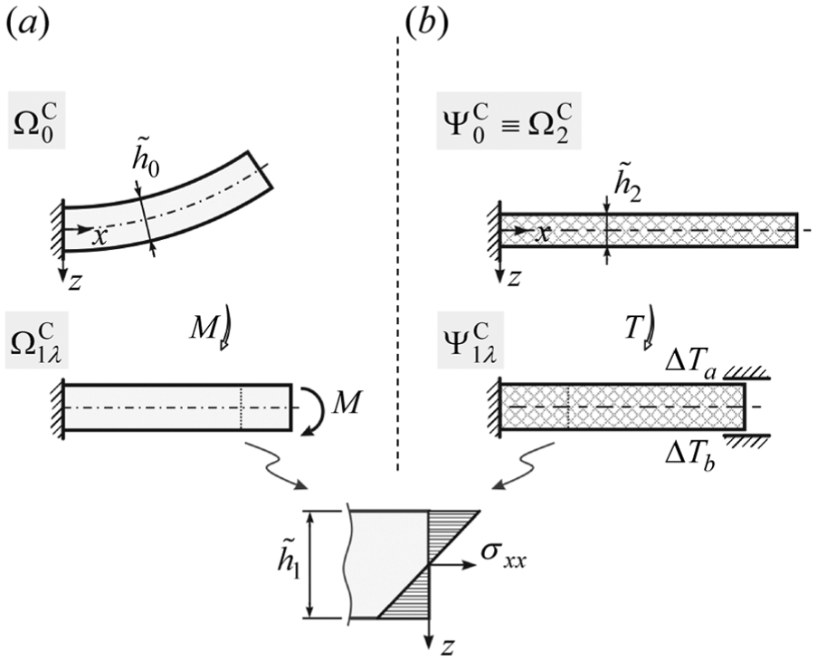
The parameters that define the TMA beam are the thermal loadings ΔTa and ΔTb and the material properties, which are Young’s modulus EΨ and the coefficients of thermal expansion in the axial αx and transverse αz directions of the beam (Figure 3(a)). Because the initial

The TMA approach: (a) TM model of the idealised beam, (b) TM model of the real beam and (c) mechanical response of the original real beam (Figure 1(a)).
Altogether, this defines up to five unknown parameters (ΔTa, ΔTb, EΨ, αx and αz). They follow from the mathematical solution of the problem, which is briefly presented in the following.
Since the initial

where
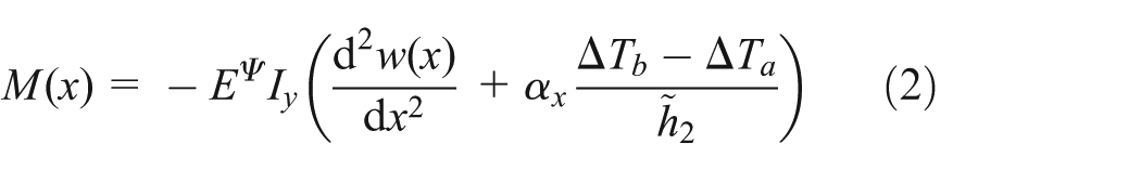
where Iy is the second moment of area. Because the beam does not deflect
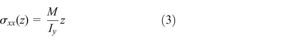
Since the distribution of stresses in the targeting configuration

The system of equations (1) and (4) represents the conditions of the problem which have to be satisfied. Since we have five unknowns (ΔTa, ΔTb, EΨ, αx and αz) and three equations, two parameters can be chosen arbitrarily, whereas the remaining three follow from the presented equations. Note that, in general, it cannot be evident which variables are (or could be) dependent on each other. In this particular case, however, that not all combinations of parameters are possible, for example, from equation (1), we can see that αx and αz together cannot be chosen arbitrarily.
The purpose of the section was to determine such properties and loadings of the TM beam
TM model of the real beam and the stresses in the real beam, sub-steps 3.2 and 3.3
So far, we have shown that the idealised beam configuration
The activities performed in sub-step 3.1 now enable us to construct a new TM model
To summarise, we have managed to obtain the residual stresses and the respective configuration of the real beam based on its loaded state configuration
Applying the TMA approach to predict the mechanical response of an arterial segment
The purpose of this section is to present how the mechanical response of a real arterial segment can be predicted using the TMA approach. For the sake of brevity, we will treat the arterial segment as single-layered, isotropic and hyperelastic. In addition, the material properties of the segment are assumed to be known.
Let us observe the arterial segment in Figure 4(a) in its loaded state

Predicting the mechanical response of a patient-specific arterial segment
This problem is treated, first, by simplifying (idealising) the geometry of the arterial segment (Figure 4(b)), performed, for instance, on area equivalence principle. For such an arterial segment, as will be shown, stresses for all of the configurations in Figure 4(b) can be determined. Next (step 3), the TMA approach is used to map the stresses of the idealised arterial segment (Figure 4(b)) onto the patient-specific arterial geometry (Figure 4(a)). Let us emphasise again that the properties of the TM model (i.e. its material behaviour and loadings) have no relation with the properties of the artery. As will be presented and clarified in the following, the behaviour of the artery is non-linear (and undergoing large deformations), whereas the behaviour of the TM model is linearised.
In the following, the same steps will be followed as presented in the beam example. Therefore, to avoid presenting the TMA approach again in detail, parallels between the problems will be drawn throughout this section.
The initial (input) data of the problem, step 1
Similar to the beam example, the data that can be obtained when treating a patient-specific artery are the loaded (in vivo) configuration of the artery
However, because we do not know the initial cut-open geometry of the arterial segment (Figure 4(a)), the stresses in its in vivo state cannot be computed. To estimate the mechanical response of the arterial segment, its shape is idealised into a circular one.
Idealised (circular) arterial segment, step 2
In this case, we know that the initial zero-stress state geometry
The key datum is the consideration of the uniform strain hypothesis.
7
Because the in vivo geometry
Furthermore, with the mechanical response of the idealised arterial segment being known, the TMA approach is performed in order to transfer the idealised configuration
TM model of the idealised arterial segment, sub-step 3.1
The purpose of this section is to obtain the residual stresses in the idealised arterial segment using an alternative approach, the idealised TM model
The remaining properties of the TM model that need to be properly determined are the temperature loadings ΔTo and ΔTi, which need to be applied to the outer and inner surfaces, and the material properties, which need to be different in the transverse (r − ϕ) and longitudinal (z) directions of the segment. This is required in order for the TM model to match the targeting configuration and the corresponding stresses.
The cross-sectional temperature distribution of the TM model is obtained by solving a steady-state heat exchange problem. During thermal loading, the TM segment is fixed in the axial direction (z) in order to obtain the proper value of axial stresses σz and to preserve the segment’s axial dimension. Additionally, because the residual stresses in
Approximation of the original (patient-specific) arterial segment’s stretched state
, sub-step 3
2. Finally, the material properties and thermal loadings of the idealised TM segment are transferred to the stress-free geometry of the patient-specific in vivo geometry
Furthermore, to obtain the state of the artery
Summary of the TMA approach
For clarity, let us once again summarise the key steps of the TMA approach in the case of treating an arterial segment (Figure 5):
From the experimental data of a patient-specific arterial segment (Figure 4(a)), that is the in vivo configuration
By adopting the uniform strain hypothesis, all of the configurations for the circular arterial segment can be computed (Figure 4(b)).
Based on the obtained stress state and configuration
The TM model of the patient-specific arterial segment
By switching the material properties and loadings of

Steps of the TMA approach for treating a patient-specific arterial segment.
Experimental data
CCA was examined in a healthy 28-year-old and non-smoking male. Prior to taking measurements, the subject was asked to rest for 15 min.
CCA geometry
The CCA in vivo configuration was obtained through the use of a high-resolution echo-tracking device, Philips iU22 (Philips Healthcare), and a L9-3 linear probe by an experienced cardiovascular surgeon. While recording the ultrasound (US) signals of the CCA transversal view, the US probe was moved from approximately 60 mm proximal to the carotid bulb to 30 mm distal to the bulb. The time of the recording was approximately 2 min, and the speed of the probe was kept nearly constant. In order to obtain the spatial position of the probe, its longitudinal movement was recorded with a camera. Throughout the measurement, the subject was monitored via electrocardiogram (ECG).
Segmentation of the artery
The US recording was first segmented into time frames. Based on the ECG data, the frames that corresponded to the CCA systolic state were selected, and points on the outer (media) wall contour of the CCA were manually picked. Since the shape of the arterial cross section is roughly elliptic,
16
we designed an algorithm that placed a best-fitting ellipse to the selected points. The longitudinal positions of the ellipses along the CCA were obtained by synchronising the US recording of the arterial transversal view and the recording of the US probe with time. Finally, by interpolating a surface through the positioned ellipses, the outer (o) systolic state (s) surface of the analysed CCA was obtained and designated as
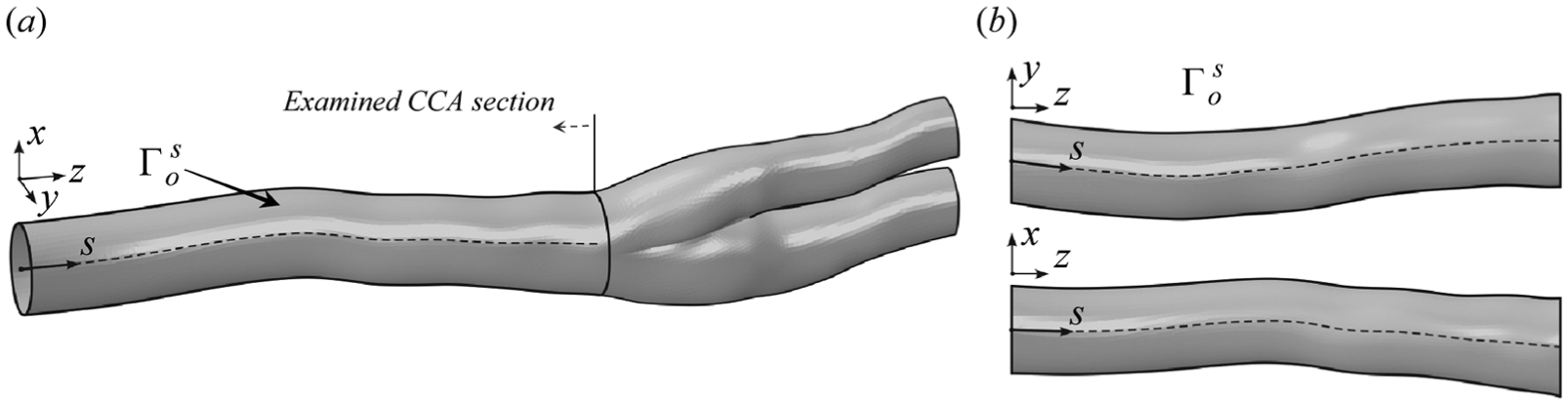
The reconstructed outer systolic surface of the CCA
CCA pressure–radii waveform
For the characterisation of a circular arterial segment based on the in vivo measured data, pressure distention data of a CCA section are needed. However, in contrast to section ‘Applying the TMA approach to predict the mechanical response of an arterial segment’, when a single arterial cross section was observed, the cross section of the CCA is variable. In this case, therefore, at least two sections along the CCA need to be observed, which are designated as sections (m) and (M). Their location along the CCA is shown in Figure 7(a), where the variation of the CCA cross-sectional area A(s) along the centreline coordinate s is presented. In the following, the aim is to obtain the pressure distension waveform for both observed sections – (m) and (M) – along the CCA.

Variation of the cross-sectional area of the surface
The CCA distension waveform
The CCA pressure waveform
Modelling the CCA mechanical response
Mechanical behaviour of the CCA
In this section, the TMA approach is applied to the observed CCA with the purpose of predicting its residual stress state. As already mentioned, in contrast to characterising a single arterial section, as was presented in section ‘Applying the TMA approach to predict the mechanical response of an arterial segment’, the cross section of the CCA is variable. This means that, in general, any number of CCA sections could be observed to define their corresponding TM segments. In this work, for the sake of brevity, two locations along the CCA are observed: locations (m) and (M), as shown in Figure 7(a).
The CCA is modelled as hyperelastic, isotropic and incompressible. For the material behaviour, the following strain energy density function is assumed 2
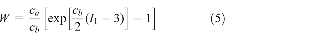
where
In this work, we will determine the values of CCA material parameters based on the in vivo data obtained. The feasibility of characterising the arterial material properties based on the in vivo clinical data was demonstrated by Masson et al., 20 Schulze-Bauer and Holzapfel 22 and Stålhand et al. 23 This is performed by treating an idealised (circular) arterial segment. In addition to obtaining the geometry of the segment’s initial configuration, the material parameters are identified as well.
Using the TMA approach, the CCA residual stress state is predicted by applying the properties of the circular TM CCA segment to the in vivo measured CCA geometry, as presented in section ‘Applying the TMA approach to predict the mechanical response of an arterial segment’. First, a circular segment of the CCA needs to be fully characterised. Then, the TMA approach is applied to ‘transfer’ the residual stresses and configuration(s) from a circular CCA segment to a patient-specific CCA geometry. Because the cross-sectional area of the CCA changes, two sections along the CCA need to be observed. For these two segments, by idealising their geometry, the material properties and the zero-stress state geometry are determined. To ‘transfer’ their mechanical response to the patient-specific CCA, two circular TM segments are then defined, each corresponding to individual circular CCA segment. Finally, to obtain an approximation of the CCA residual stress state, the properties of both TM segments (i.e. their loadings and material properties) are interpolated/extrapolated along the CCA and applied to the CCA stress-free in vivo geometry
Circular CCA segments
The purpose of this section is to characterise the two circular CCA segments. The segments correspond to positions (M) and (m) along the CCA. Luminal (inner) diameter of segments is obtained from the luminal cross-sectional area of the CCA (measured at its corresponding locations, Figure 7(a)). Segments are treated with the purpose, on one hand, of obtaining the material properties of the CCA and, on the other hand, of obtaining the referential residual stress state(s), based on which the TM model will then be calibrated.
First, the segment (M) is treated, and its initial geometry and CCA material properties are identified. Afterwards, by adopting the obtained material properties, the segment (m) is characterised in order to determine its initial zero-stress geometry.
The parameters that need to be determined for the circular arterial segment (M) are the zero-stress state radius
The identified properties of the circular arterial segments (M) and (m).

After adopting the obtained material parameters, the segment (m) is treated next in order to identify its zero-stress state radius
Circular TM segments
With circular CCA segments (M) and (m) completely defined, the properties and loadings of their corresponding TM segments, (M) and (m), can be determined next. First, the segment (M) is treated. Its initial geometry is defined based on the in vivo (systolic) stress-free geometry of the CCA segment (M), whereas its properties are determined in such a way that its loaded state matches the CCA segment’s stretched state
The properties of TM segments that are common for both segments are
In computing the mechanical response of the TM model, we can treat the problem as a sequentially coupled steady-state thermal-stress problem. This means that, first, the steady-state heat conduction problem must be solved, where the temperature distribution over the thickness of the segment is obtained based on the applied thermal loadings. The obtained temperature field is then applied as the loading to the stress analysis in order to obtain the mechanical response of the TM model. The mathematical relations that are needed to compute the steady-state thermomechanical response of the circular TM segment are given in Appendix 3.
The values of the unknowns defining both circular TM segments are obtained by solving a minimisation problem, as shown in Appendix 3. The obtained best-fit values are presented in Table 2.
The identified properties of the TM circular segments.

TM: thermomechanical.
In the following, the obtained parameters of both TM segments are applied to the in vivo stress-free geometry of the CCA. However, since some parameters refer to each TM segment individually, their values first have to be properly interpolated/extrapolated in order to be applied to the CCA in vivo geometry.
Generalising the properties of the TM segments
In order to apply the properties of the circular TM segment to the in vivo CCA geometry, the properties that refer to the individual TM segment (
A linear interpolation of a variable, say,

where
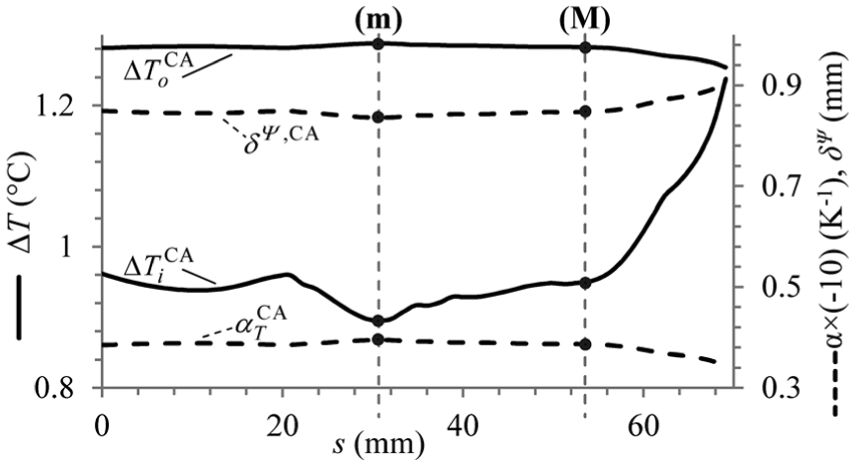
Variations of the fictitious CCA model properties:
The parameters that are assumed the same for both TM segments (m) and (M) are also assumed to be constant along the CCA.
TM model of the CCA
To obtain the approximation of the CCA residual stress state (i.e. stresses and geometry), we apply the parameters and loadings that were obtained for the circular TM segments to the in vivo CCA stress-free geometry
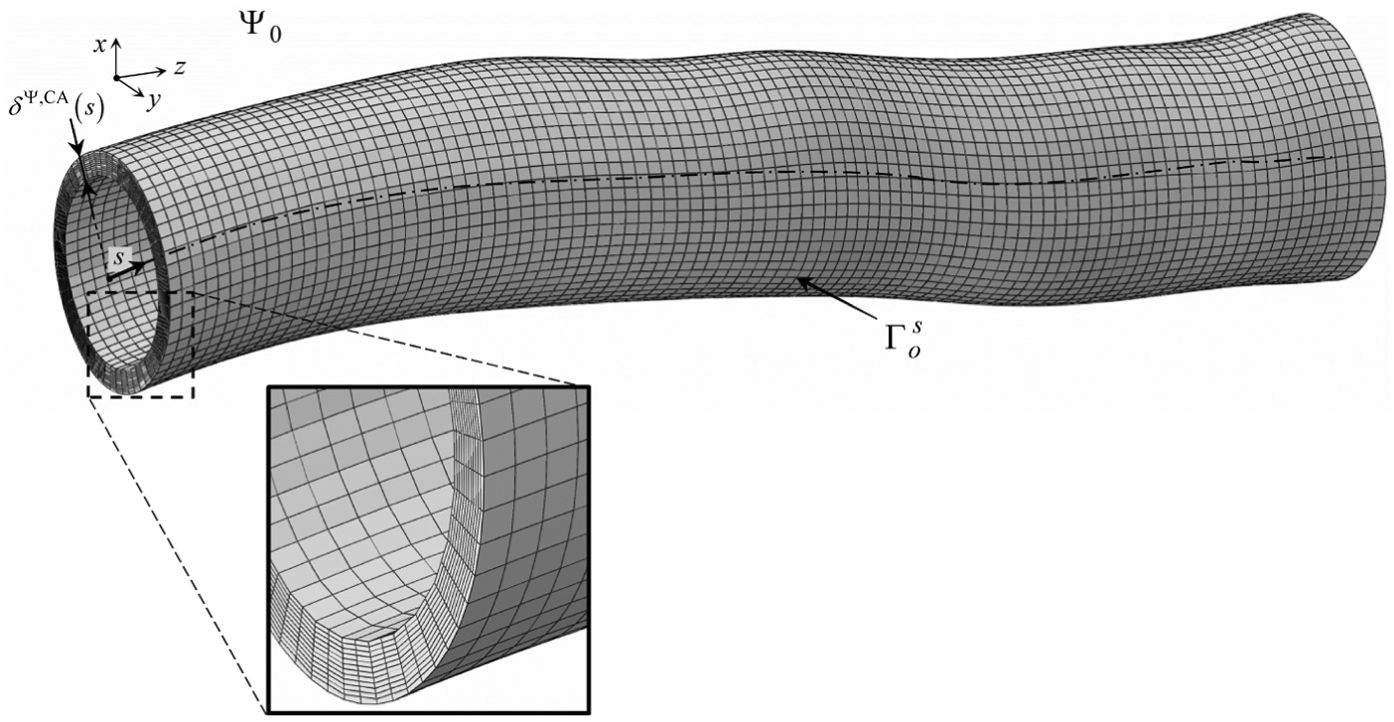
Finite element model of the TMA CCA model
Note that the thickness of the model
Results and discussion
Numerical computations of the TMA and the arterial CCA model were performed with ABAQUS/Standard. In the following, the predicted CCA stretched state
Stretched state of the CCA
The predicted CCA stretched state
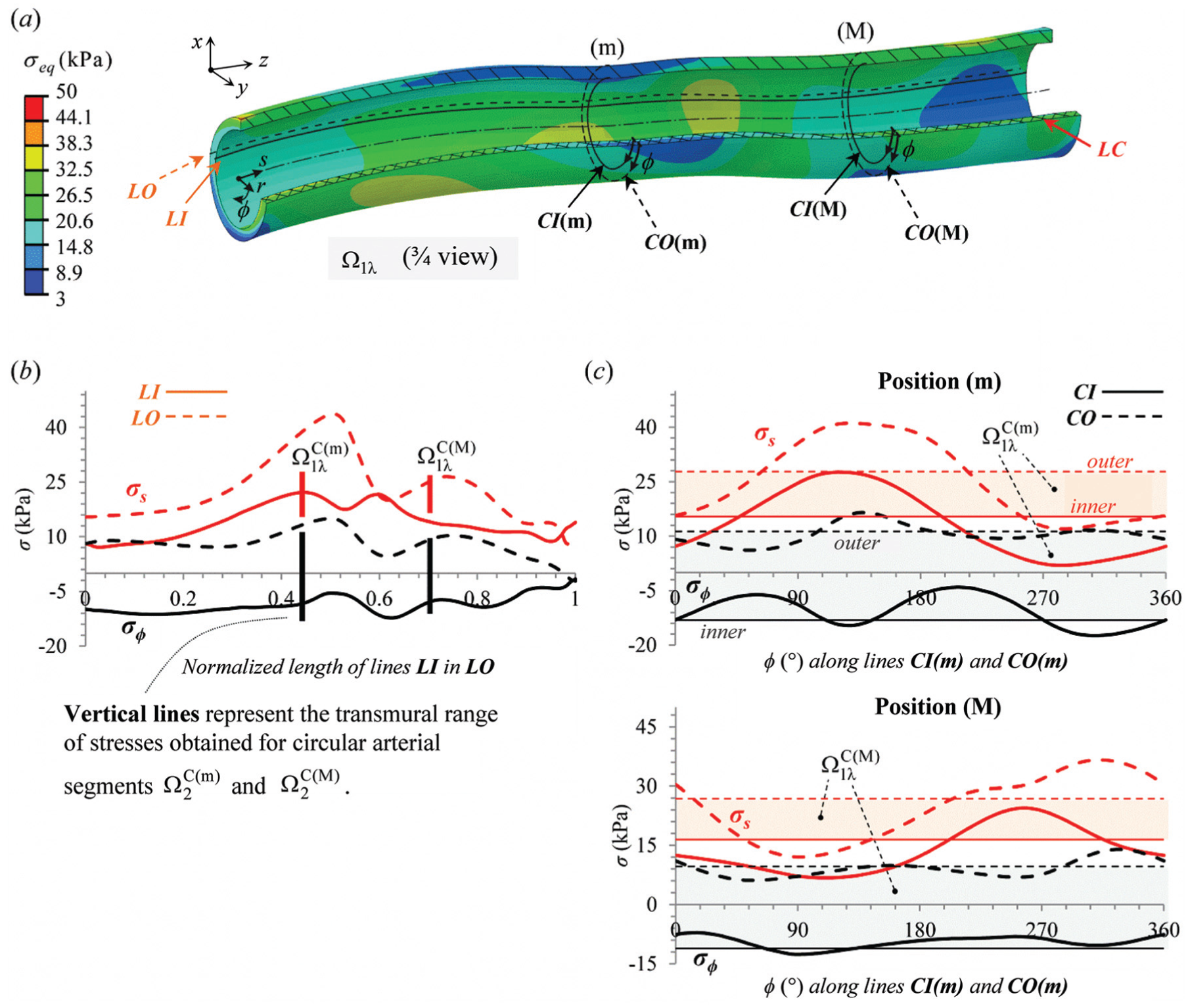
The predicted CCA stretched state (
The comparison of our results with the data from the literature serves as a quantitative validation of the approach. We need to emphasise that the validation of the predicted residual stress of the CCA could be performed only experimentally, which is beyond the scope of this work.
Furthermore, let us compare the stresses predicted for the CCA stretched state with the stresses predicted by the circular arterial segments (M) and (m), designated as
The variations of CCA stresses along lines
Loaded state of the CCA
The predicted CCA systolic state (
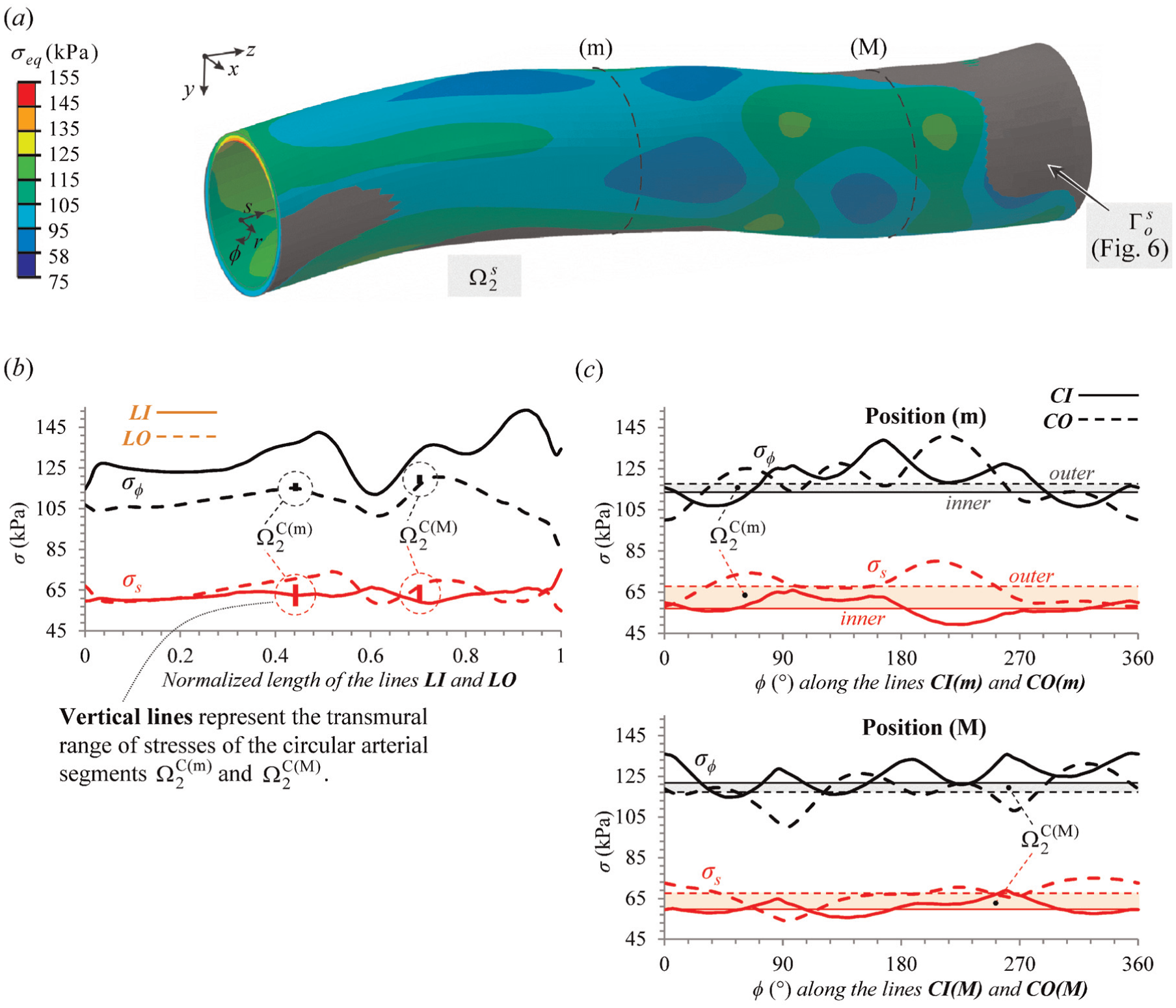
The predicted CCA systolic state (
Moreover, the transmural range of
The variation of the CCA stresses along lines
In Figure 11(a), the comparison between the predicted CCA configuration and the measured CCA surface in vivo
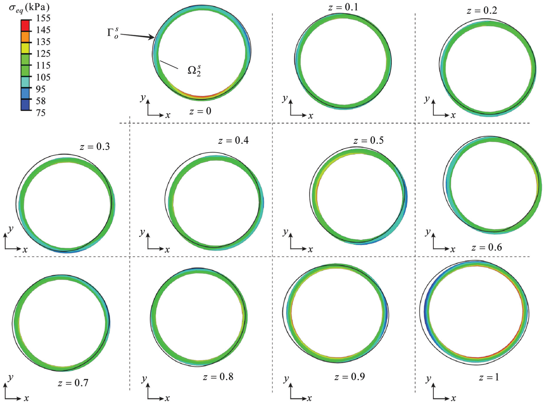
Individual cross sections of the model presented in Figure 11(a), obtained by dividing the model in Figure 11(a) into 10 equidistant parts along the coordinate z– note that the cross sections of the surface
Zero-stress state of the CCA
The appropriateness of the TMA approach for predicting the CCA residual stress state can be validated by predicting the CCA zero-stress state configuration
An approximation of the CCA zero-stress state
The peak value of the von Mises equivalent stress in

Predictions of the CCA zero-stress state: (a) the cut-open state of the CCA
Conclusion
Many soft biological tissues show volumetric growth which results in the development of residual stresses in their load-free configuration.8,27,28 In this work, the residual stress state of a human CCA is predicted using the TMA approach. The approach is used in order to perform kinematically and statically consistent mapping of the residual stress state obtained for a circular arterial segment (i.e. its stresses and the corresponding configuration) onto the patient-specific arterial geometry.
CCA is examined on a healthy 28-year-old male using non-invasive methods, where an isotropic and hyperelastic material model was used to account for the CCA’s mechanical behaviour. With TMA approach, the CCA’s residual stress state is obtained by applying proper volumetric dilatations to the actual stress-free in vivo CCA geometry. The amount of the applied dilatation is obtained by observing two individual CCA sections and predicting their mechanical responses by idealising their geometry into a circular one. The predicted CCA residual stresses are in good quantitative agreement with the data of residual stresses in arteries found in the literature. Additionally, in order to validate the approach, first, the predicted CCA loaded state geometry was computed to the measured CCA geometry. The agreement between both data was found to be satisfactory. Second, the zero-stress state of the CCA is predicted. As known in the literature, a cut-open state is obtained with the residual stresses almost vanishing.
A limitation of this work is that the artery is treated in a rather simplified manner by adopting an isotropic material behaviour and a one-layer structure. However, since the TMA approach performs or affects only the mapping from a circular arterial segment to patient-specific arterial geometry, considering a multi-layered structure and an anisotropic material behaviour does not represent a limitation for the approach.
In applying the approach to an artery of a variable thickness, as occurs in the case of atherosclerotic arteries, the uniform strain hypothesis is questionable. Still the presented approach is applicable with a new assumption adopted that would have to be identified based on experimental data of atherosclerotic arteries.
The benefit of the approach is that it enables the use of medical image acquisition techniques (such as magnetic resonance imaging (MRI), computed tomography (CT) or US) to model the artery’s residual stresses and its respective configuration. The inability to predict the arterial residual stress state configuration represents a major drawback of most of the existing methods in the literature. Although these methods predict the residual stresses, the prediction of the corresponding arterial geometry is not that trivial and iterative approaches need to be used, as for instance presented in Sellier. 29 Along with the non-invasive medical imaging techniques, we believe that the TMA approach could serve as a useful tool to develop a better understanding of the in vivo stress state of patient-specific arterial geometry.
Footnotes
Appendix 1
Appendix 2
Appendix 3
Academic Editor: Ruey-Jen Yang
Declaration of conflicting interests
The author(s) declared no potential conflicts of interest with respect to the research, authorship, and/or publication of this article.
Funding
The author(s) received no financial support for the research, authorship and/or publication of this article.