
Abstract
In this contribution, a four-bar linkage having a variable input velocity is studied, traditionally it is assumed to be constant. The advantages of a variable input velocity mechanism, in contrast to a mechanism driven by constant velocity, are the flexibility of the output motion (and/or improved kinematic and dynamic characteristics). The velocity of the crank is controlled in order to obtain the desired output motion at the coupler point. The input velocity trajectory and the controller parameters are considered as design variables, such that the kinematic and dynamic requirements are fulfilled. Two numerical examples are provided to corroborate the result.
Introduction
Traditionally, the dimensional synthesis of first-order mechanisms comprises the problems of path, function, and motion generation which is known as finite synthesis. However, under certain conditions, it is required to consider in the design of mechanisms the velocity and/or acceleration as requirements to be met. 1 When velocities and/or accelerations are considered in the design problem, the synthesis is known as higher-order synthesis. 2 There are many situations in the design of mechanical devices in which it is necessary to deal with constraints of velocity. For example, there is a real need for straight-line motions in machinery of all kinds, especially in automated production machinery. Economic considerations continually demand higher production rates, requiring higher speeds or additional expensive machines. When the product is in continuous motion in a straight line and at constant velocity, every workhead that operates on the product must be articulated to chase the product and match both its straight-line path and its constant velocity while performing the task. 3 Several works have been published dealing with the mechanism design with velocity targets.
In particular, the higher-order synthesis for function generation has been studied in Ángeles Álvarez, 1 Erdman and Sandor, 2 and Sandor et al. 4 The optimal design of a four-bar linkage for path generation task where a coupler point must satisfy certain conditions for position and velocity was performed in Norton, 3 Schaefer and Kramer, 5 Holte et al., 6 Robson and McCarthy, 7 Ureña et al., 8 De-Juan et al., 9 and Russell and Shen. 10 One of the basic assumptions in both the synthesis and analysis of the four-bar mechanism in many design cases is that the angular velocity of the input link is constant. This assumption is essential for the design of a mechanism in which timing requirements are involved. However, this assumption may not be valid if an electric motor is connected to drive the mechanism. 11 Moreover, in all above works, the problem of fulfilling the desired velocity profile was addressed from a dimensional synthesis point of view; this solution fulfills the velocity requirements only at the designs points and not in all the trajectory. If the desired velocity profile is changed and we are in an early stage of design mechanisms, like kinematic synthesis, it is relatively easy to calculate the new parameters of the mechanism that meet the requirements of the desired task. However, if the mechanism is already operational and it is imperative to work with a new operating speed, for example, the required parameters of production speed vary, a complete redesign of the mechanism would be necessary.
Recently, an alternative approach for achieving this purpose without modifying the geometric dimensions of the existing mechanism was presented in Yang et al., 12 where was developed and designed a model of variable input speed of a compound mechanism with a slider-crank and a screw mechanism for improving the kinematic and dynamic characteristics. Here, Bezier functions are used as the desired velocity profile. Also, a novel concept of a four-bar mechanism equipped with a continuously variable transmission (CVT) has been proposed to obtain variable input speeds is presented in Yildiz et al. 13 Thus, different manufacturing operations and transportations can be performed with the same mechanism without using an electrical inverter or changing the electrical motor. But in these approaches above was employed another mechanism to drive an existing mechanism to improve it.
In the present work, we are interested in moving the coupler point with a constant velocity, avoiding the mechanism redesign or using another mechanism to drive the existing mechanism, by controlling the angular velocity of the input link. This input desired velocity profile is achieved using a proportional–integral–derivative (PID) controller.
The equation of motion and mathematical model for the motor and PID controller are established to analyze the dynamic response of a servo-motor-driven four-bar linkage for a variable input speed. In this way, a constant speed in the coupler point over the complete cycle or range of motion can be reached.
This article is organized as follows: in section “Input speed profile,” the input profile angular velocity function is presented in order to fulfill the velocity target. The mathematical model of the motor-driven mechanism system is presented in section “Mathematical model of the system.” In section “Velocity controller,” we analyze the stability of the closed-loop system consisting of the PID controller. Illustrative examples for the problem of velocity tracking, to demonstrate the effectiveness of the control scheme, are shown in section “Simulation results.” Finally, some conclusions and future developments are exposed in section “Conclusion.”
Input speed profile
The advantages of a variable input speed mechanism, in contrast to a mechanism that is driven with constant speed, are the flexibility of the output motion and improved kinematic and dynamic characteristics. 14 In what follows, the representation of the input speed trajectory is derived.
Coupler point velocity
The position of point P (see Figure 1) viewed from the inertial frame is given in equation (1)

where


General four-bar linkage.
Now, replacing equation (2) in equation (1) results in

The linear velocity for the point P can be derived by continuously differentiating equation (3) with respect to time as follows

where

and
Desired angular velocity profile function
From equation (4), we can obtain the linear velocity magnitude for the point P as follows
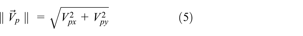
As can be noted, if

Mathematical model of the system
Dynamics of the four-bar linkages
Figure 1 represents a general four-bar linkage. Link 2 (crank) is driven by an electrical motor, and it is able to perform a complete rotation. Link 3 (coupler) performs a general motion in the plane, and it transmits the movement to link 4 (rocker), which executes an oscillatory motion. In Figure 2, the center of mass for each body is denoted by a dark circle, and their locations are described by

Four-bar mechanism.
The Lagrange’s equation can be written to obtain the equations of motion for the mechanism as
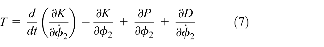
where

where

with

After an algebraic manipulation, equation (8) can be written as

where

with

The potential energy of the four-bar mechanism is due to the gravity, and it can be expressed as

The dissipative energy for the four-bar mechanism can be neglected, because there is no viscous torque present.
Replacing energy equations (8) and (11) in equation (7), the mechanical torque of the system is obtained as

Mathematical model for the mechatronic system
A schematic diagram of the electric motor is demonstrated in Figure 3. The gear ratio is given as

where

Schematic diagram of a motor and a gearbox.
Using Kirchoff’s voltage law and Newtonian’s equation for the mechanism load, we have


where
Equation (13) and


Now, the torque produced by the motor should be equal to the torque needed for the mechanical system, yielding this to the nonlinear equation of motion. In order to determine this equation, one can match equation (12) with equation (17), neglecting the terms related with the potential energy in equation (12) due to the orientation of operation of the mechanism, the resulting expression is

In order to obtain a dynamical system including the mechanical and electrical dynamic, let us define the change of variables


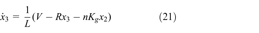
where

Note that the control input to the system is now the voltage v and the output variable is the angular velocity of the crank (
Velocity controller
The control scheme described in this work consists of two loops. The first one obtains the current reference (
The control synthesis begins defining the current tracking error as

From equation (22), a linearizing PID control signal can be proposed as

where

Introducing the control law (23) into the error dynamics (22), this is reduced to
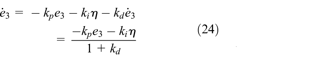
where the error dynamics can be globally and asymptotically stable if the gains
As can be noted, if the control law (23) includes the current reference (

Replacing

Taking into account that the first control loop quickly assures

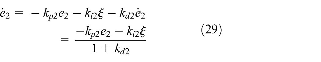
As

where

Then, replacing the control law (28) into the velocity error dynamics (27), we can obtain
In order to verify the stability of the complete closed-loop system, a Lyapunov candidate function is proposed as

where

and

where
Then, if

The above result satisfies the stability condition that if
It is important to remark that in the stability proof, the error

Complete control scheme.
Simulation results
In order to verify the performance of the proposed control law, simulations for two different four-bar linkages, each one with its own path, were conducted. The two mechanisms and their respective paths are presented in Figure 5. For convenience, from now on, they are appointed as mechanism 1 and mechanism 2. The test consists of regulating the coupler point linear velocity

Four-bar mechanisms with coupler point paths: (a) mechanism 1 and (b) mechanism 2.
Mechanism parameters.

Motor parameters.

Controller gains.

Mechanism 1 simulation
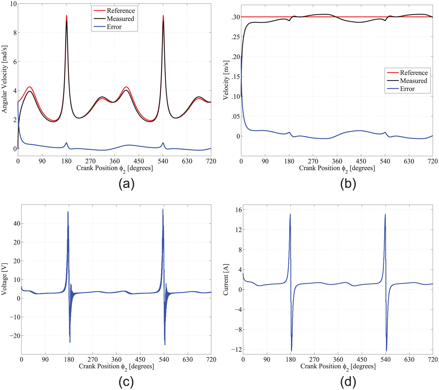
The path generated by the coupler point mechanism 1 is presented in Figure 6(a). So as to ensure that the coupler point travels its path at desired speed, the Crank of the mechanism must follow the angular velocity profile shown in Figure 6(b). In Figure 7(a), it can be observed that maximum error in the profile tracking is about 0.33 rad/s. Consequently, the obtained linear velocity of the coupler point error is over 0.017 m/s. Figure 7(b) evidences this fact. Figure 7(c) and (d) present both voltage and current requirements needed to complete the task. It can be noted that the magnitude of this variables is bounded, so the control is realizable, because power consumption is finite. As can be observed, the imposed speed for the path of mechanism 1 is reached without drawbacks. So, a test under more severe conditions is necessary to verify the performance of the proposed control scheme; by this motive, mechanism 2 was selected. Where mechanical architecture is of the same type, with slightly different dimensions and inertial properties, the path generated to a point of the coupler link has an abrupt change in direction in an instant of time very small.
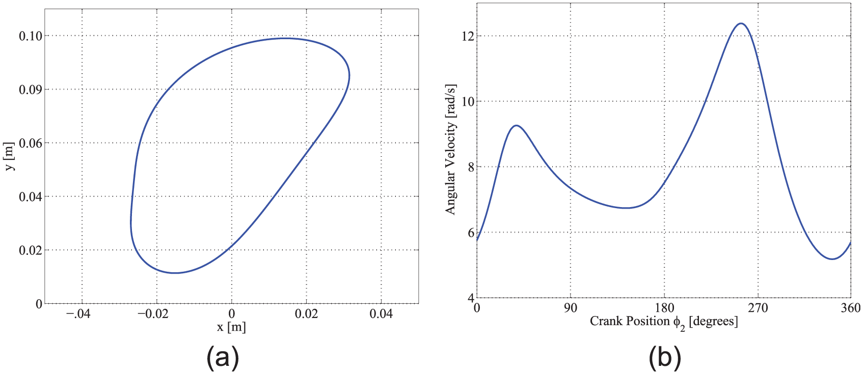
(a) Mechanism 1 path and (b)

Mechanism 1 behavior: (a)
Mechanism 2 simulation
In this case, the path of the coupler point of mechanism 2 is shown in Figure 8(a), and the angular velocity profile is shown in Figure 8(b). The profile tracking is described in Figure 9(a), where the maximum error is about 0.39 rad/s. Thus, the linear velocity of the coupler point error is over 0.013 m/s. This result verifies that the control objective satisfactorily complies. However, it can be seen that there are voltage peaks and current peaks at 180° of the crank, corresponding to the inflection point of the trajectory, as it is exhibited in Figure 9(c) and (d). Despite these peaks, it is important to mention that the feasibility of using the proposed control is because the peak voltage and current values are bounded.

(a) Mechanism 2 path and (b)
Mechanism 2 behavior: (a)
Conclusion
The PID controller used in this work for the motor-mechanism coupling, with the target to control the linear velocity coupler point (
Footnotes
Acknowledgements
The authors thank PRODEP, Conacyt, and SNI for their support.
Academic Editor: Yangmin Li
Declaration of conflicting interests
The author(s) declared no potential conflicts of interest with respect to the research, authorship, and/or publication of this article.
Funding
The author(s) disclosed receipt of the following financial support for the research, authorship, and/or publication of this article: They received financial support by part of PRODEP for publication of this article.