
Abstract
Accurate position control of pneumatic artificial muscle actuated systems has always been difficult due to their inherent nonlinear hysteresis characteristics. This article designs a bio-inspired semi-active robotic joint that is synergistically driven by a pneumatic artificial muscle and an extension spring by imitating the mechanism of energy storage and return in animals and then studies its position tracking control with hysteresis compensation. To simplify the derivation of the inverse hysteresis model which functions as hysteresis compensator, a novel approach termed as direct inverse hysteresis modeling is adopted. With this method, the inversion of the asymmetric angle–pressure hysteresis of the semi-active joint is modeled directly from experimental measurements by a modified Prandtl–Ishlinskii model. On the basis, a closed-loop position tracking controller composed of forward hysteresis compensation and conventional proportional–integral–derivative control is designed for the joint. Experimental results indicate that the proposed controller can track the reference position signals with high accuracy.
Keywords
Introduction
Pneumatic artificial muscles are a kind of non-traditional and compliant actuators which can simulate the behavior of biological muscles. In contrast to electric motors and hydraulic actuators, pneumatic artificial muscles have high power-to-weight ratio, low cost, and inherent compliance. 1 These unique advantages have promoted increasingly broad applications of pneumatic artificial muscles in bionic robots,2–4 rehabilitation robots,5,6 prostheses and orthoses,7,8 and other areas where safe human–machine interactions are required.
However, there still exist some problems and difficulties with regard to pneumatic artificial muscles acting as joint actuators in practice. On one hand, only being able to generate contraction force, two pneumatic artificial muscles are usually arranged in antagonistic pair to achieve bidirectional motion for a single-degree-of-freedom joint.9,10 Unfortunately, this arrangement makes the joint over-actuated, meanwhile, results in bulky mechanical and electrical structures if fist-sized proportional valves are adopted as pressure regulators. 11 On the other hand, pneumatic artificial muscles exhibit strong inherent hysteretic behavior, which is caused by many perplexing factors. This makes it complicated to understand and handle the characterization of pneumatic artificial muscles, bringing about many difficulties in designing controllers for high-performance positioning systems. These above issues need to be addressed as they have affected further application of pneumatic artificial muscles.
Up to present, extensive researches have been conducted aiming at the control of nonlinear systems such as active suspension systems, multilateral teleoperation systems, systems with friction, and systems with non-symmetric dead-zone.12–16 For pneumatic artificial muscle actuated systems, to improve position tracking performance, many intelligent controllers are proposed: from nonlinear proportional–integral–derivative (PID) controller 17 to fuzzy controller, 18 from neural network controller 19 to adaptive robust controller, 20 and from sliding mode controller21,22 to hybrid controller.23,24 However, these controllers have some shortcomings such as dependence on model accuracy and heavy computation load. Moreover, they increase the control complexity since there are many parameters that are difficult to quantify.
The originality of our research consists in dealing with the position tracking control of a semi-active pneumatic-driven robotic joint. Our main contributions lie in the following aspects. First, a bio-inspired semi-active joint that is synergistically driven by a pneumatic artificial muscle and an extension spring is designed by imitating the mechanism of energy storage and return in animals. Second, the idea of hysteresis compensation is further extended to the pneumatic-driven joint from some hysteretic systems such as electromagnetic actuators, 25 magnetostrictive actuators, 26 as well as piezoceramic actuators.27,28 Third, to facilitate the derivation of the inverse hysteresis model of pneumatic artificial muscles, a much more straightforward method is proposed, termed as the direct inverse hysteresis modeling approach. More specifically, with the joint taken as a gray box, the input–output relationship, that is, the relationship between the supplied pressure and joint angle that exhibits hysteresis is measured, and then, the inverse hysteresis model which maps the joint angle to the pressure is built from experimental measurements by a modified Prandtl–Ishlinskii model. The modified Prandtl–Ishlinskii model utilizes two asymmetric play operators to describe the ascending branch and descending branch of the hysteresis loops, respectively. And fourth, a simple but effective closed-loop position controller composed of forward hysteresis compensation and PID feedback control is designed for the joint.
The remaining content of this article is organized as follows. Section “The bio-inspired semi-active joint” introduces the bio-inspired semi-active joint including its mechanical structure and hysteresis characteristics. Section “Direct inverse hysteresis modeling” presents the direct inverse hysteresis modeling approach and the modified Prandtl–Ishlinskii hysteresis model in detail. The position tracking control scheme of the joint is presented in section “Position control of the semi-active joint,” with its validity verified through experiments. Finally, some discussion and conclusion are given in section “Conclusion.”
The bio-inspired semi-active joint
Design of the bio-inspired semi-active joint
Pneumatic artificial muscle is an appropriate compliant actuator for robotic joints. But antagonistically arranged muscles for achieving bidirectional joint motion often result in over-actuation and bulky mechanical and electrical structure. Besides, in some self-contained robots, compressed air is supplied to the muscles from an air tank. The limited amount of air inside the tank definitely affects the system operating time. There is no doubt that it will be beneficial to realize bidirectional joint movement with less pneumatic artificial muscles. Through research, biologists found that distal limbs of many animals including humans, horses, and wallabies could store and return energy in their spring-like tendons, functioning like a pogo stick throughout the cyclical locomotion. The elastic energy stored in and recovered from tendons could help reduce the metabolic cost of locomotion. 29 Inspired by animals, the mechanism of energy storage and release which may be a possible solution to the previous issues is incorporated into the design of the robotic joint.
Figure 1 depicts the schematic diagram and physical structure of the bio-inspired joint with single degree of freedom designed in this article. Rather than two antagonistic muscles, the joint is actuated by a pneumatic artificial muscle and a passive extension spring in parallel, of which the spring is used for energy storage and return. The pneumatic artificial muscle and the spring are connected by steel cable wrapping on the pulley, making the direction of the pulling force always along the steel cable. Thus, the control of the joint is facilitated due to the simple geometrical relationship between muscle contraction and joint angle. 30 The pneumatic artificial muscle is manufactured by Festo, with a working length of 180 mm and a diameter of 20 mm. The stiffness and initial tension of the spring are 1.47 N/mm and 19.61 N, respectively. The rotation of the joint in the anticlockwise direction is driven by a passive spring, hence, the joint is called a “semi-active joint” (or “semi-passive joint”, if you like). This semi-active joint has several benefits including active position controllability, passive joint compliance, as well as low energy consumption.
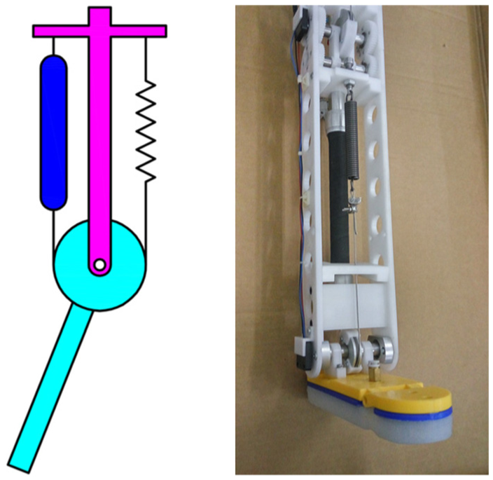
Schematic diagram and physical structure of the bio-inspired semi-active joint.
Angle–pressure hysteresis of the semi-active joint
Pneumatic artificial muscles possess inherent hysteresis characteristics. The same effects causing hysteresis in a single pneumatic artificial muscle will also result in hysteresis behavior in the semi-active joint. In order to facilitate further study, the hysteresis behavior the joint shows should be obtained. Therefore, by regarding the whole joint as a gray box, the relationship between the input, that is, the supplied pressure, and the output, that is, the joint angle, is measured through experiment.
To reduce the impact of the acceleration of joint links, the experiment was carried out under the assumption of a quasi-static process. Compressed air was supplied to and exhausted from the pneumatic artificial muscle through a proportional pressure regulator. The pressure inside the muscle and the joint angle were measured by a pressure transducer and an angular potentiometer, respectively. The process of the experiment is described as follows. In the initial state, the muscle and the spring were at their nominal length with zero gauge pressure inside the muscle. Then, the muscle was pressurized and depressurized following a reference pressure signal in the form of triangle wave with various amplitudes. The amplitudes decreased from 0.4 to 0.2 MPa at a constant interval of 0.05 MPa. The measured angle–pressure curves are shown in Figure 2, which exhibit asymmetric hysteresis loops including major loop and minor loops.
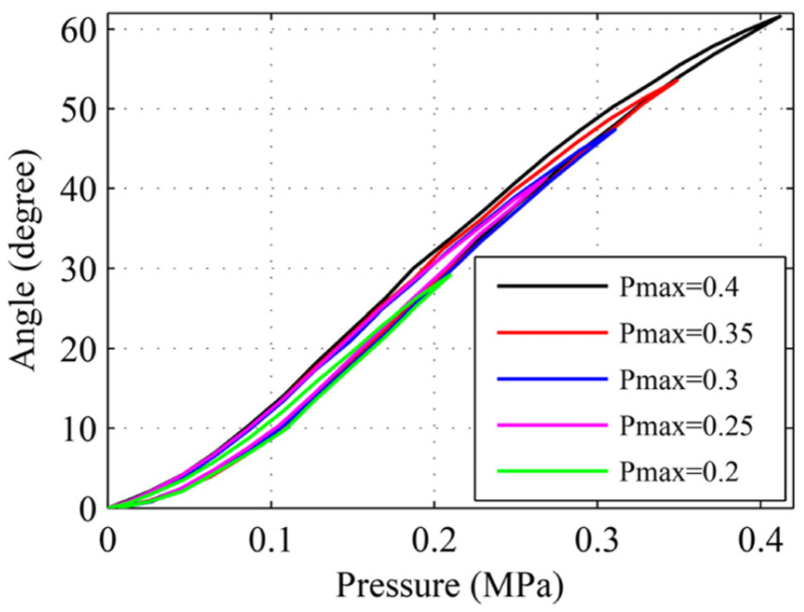
The measured angle–pressure hysteresis behavior.
Direct inverse hysteresis modeling
The direct inverse hysteresis modeling approach
Hysteresis compensation is widely used in the control of nonlinear hysteretic systems. The main concept of hysteresis compensation is that putting the inverse hysteresis model in cascade with the physical hysteretic system, thereupon, the hysteresis of the system and its inversion can cancel out each other, achieving a pseudo-linear system. The most critical process of this method is to obtain the exact inverse hysteresis model. At present, the inverse hysteresis model is usually mathematically calculated from the forward hysteresis model of the system which is built from the measured hysteresis behavior. But the derivation of the analytic inversion often requires massive calculation. Even worse, sometimes it is quite difficult or somehow impossible to get the analytic inverse model.
As to the semi-active joint, since the angle–pressure hysteresis maps the input of the joint, that is, the pressure, into the output, that is, the joint angle, its inversion is on the contrary, mapping the joint angle into the pressure. In fact, it is clear from the illustrations in Figure 3 that the ideal inverse hysteresis is the reflection of the measured angle–pressure hysteresis about the 45° line. Therefore, an idea naturally comes to mind that whether it is possible to model the ideal inversion directly from the measured data to avoid complex calculation. As an attempt, a novel inverse hysteresis modeling method is adopted in this article, namely, direct inverse hysteresis modeling approach. In practical terms, treating the joint angle and pressure as the input and output, respectively, the inversion of angle–pressure hysteresis is directly modeled from the experimental measurements.

Angle–pressure hysteresis and its ideal inversion.
The modified Prandtl–Ishlinskii hysteresis model
The classical Prandtl–Ishlinskii hysteresis model is a powerful tool for hysteresis modeling. It uses the summation of a finite number of weighted backlash operators with different thresholds to characterize hysteresis behavior in the continuous space, as presented in Figure 4.31,32 But it only works well for symmetric hysteresis, unable to model the inverse angle–pressure hysteresis of the semi-active joint which is shown to be asymmetric. For this reason, a modified Prandtl–Ishlinskii model is proposed based on the classical Prandtl–Ishlinskii model. This model utilizes two modified asymmetric play operators to describe the ascending branch and descending branch of the hysteresis loops, respectively.
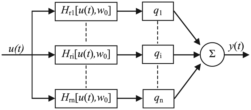
Block diagram of the classical Prandtl–Ishlinskii model.
Analytically, suppose that Cm represents the space of the piecewise monotone and continuous functions, and 0 = t0 < t1 < ··· < tN = tE are subintervals in [0, tE]. For any piecewise monotone input function u(t) ∈ Cm[0, tE] → [0, 1], and a given threshold value ri which satisfies 0 ≤ ri < 1, the elementary play operator of the ascending branch is defined as

Similarly, the elementary play operator of the descending branch is defined as

The input–output relationships of the play operator of the ascending branch and of the descending branch are presented in Figures 5 and 6, respectively.

Play operators of the ascending branch.

Play operators of the descending branch.
Calculating the weighted sum of the two play operators, the output of the modified Prandtl–Ishlinskii hysteresis model can be written as
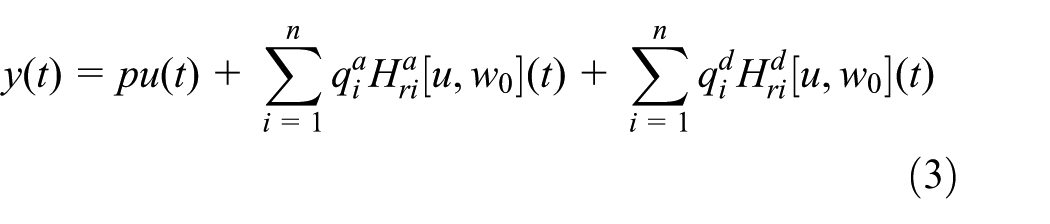
where p is a constant parameter, n is the number of play operators,
The two play operators are subject to the following constraints
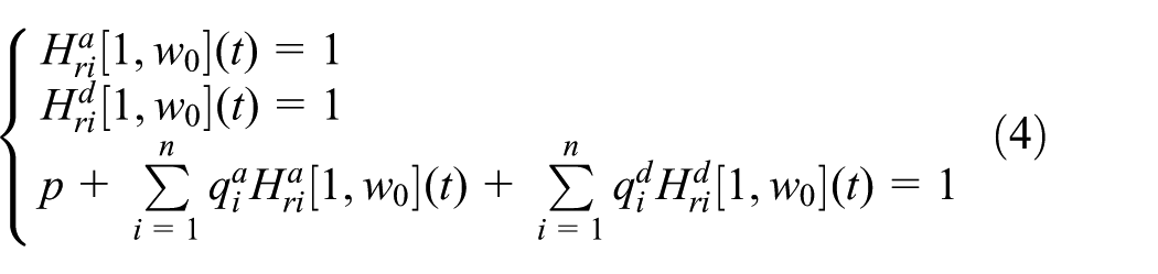
Substituting equation (4) into equation (3), the output of the hysteresis model can be rewritten as

The identified modeling results
The parameters of the modified Prandtl–Ishlinskii hysteresis model were identified using recursive least mean square algorithm. Under the premise of the iteration law, the parameters could converge to stable values within a few steps of iteration. Figure 7 shows the comparisons between the measured data and the identified modeling result. These approximately overlapping loops suggest that the direct inverse hysteresis model is feasible to characterize the inverse angle–pressure hysteresis of the semi-active joint with sufficient accuracy, allowing it to be used for hysteresis compensation.

Modeling result of direct inverse hysteresis model.
Position control of the semi-active joint
The control scheme
In order to achieve better position tracking performance, a closed-loop controller which combines a forward hysteresis compensator and PID feedback controller is designed for the semi-active joint. The block diagram of the control scheme is presented in Figure 8. The control scheme works as follows. The target value denoted as θd is the desired angular displacement of the semi-active joint. The hysteresis compensator generates the predictions of the control pressure signal Uh. According to the error between the desired angle and the feedback of the measured angle, the pressure controller which adopts PID control scheme gives a proper additional value to the total pressure signal for correcting the discrepancy of hysteresis model errors. The controller adjusts the pressure inside the pneumatic artificial muscle by sending varying analog voltages to a proportional pressure regulator. Theoretically, the output of the joint should follow the reference input.

The position control scheme of the semi-active joint.
Experiment
The proposed control scheme is applied on the physical joint to evaluate its performance. For comparison purposes, an open-loop controller which only consists of hysteresis compensator and in the same time without feedback is also tested. In the experiments, two waveforms are adopted as reference contraction signals: one is a triangle waveform signal and the other is a sinusoidal signal, both with a period of 5 s and variable amplitudes.
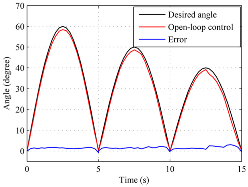
Figures 9 and 10 present the position tracking performance of the open-loop controller and the closed-loop controller, respectively, in the case of the triangle waveform signal. From Figure 9, it can be easily seen that the open-loop controller can basically track the reference signal. But relatively large tracking errors exist, and the maximal value reaches 3.68°. The factors producing these errors may include inverse hysteresis model errors, assembly errors, and uncertainty of measurements. Some errors can be eliminated at some degree using a closed-loop PID controller. In this experiment, the PID pressure controller generates an additional value to the total pressure signal according to the errors between the measured and desired joint angels. As shown in Figure 10, the tracking errors of the closed-loop controller are significantly decreased, with the maximal tracking error of 0.89° which is only about 1/4 of the open-loop controller.

Experimental result of the open-loop controller in the case of triangle waveform signal.

Experimental result of the closed-loop controller in the case of triangle waveform signal.
The experimental results of the open-loop controller and the closed-loop controller obtained under the sinusoidal signal are shown in Figures 11 and 12, respectively. From Figures 11 and 12, some conclusions similar to those outlined above can be obtained. Taken together, all experimental outcomes suggest that the proposed closed-loop control scheme can accurately track the reference position signals.
Experimental result of the open-loop controller in the case of sinusoidal signal.

Experimental result of the closed-loop controller in the case of sinusoidal signal.
Conclusion
Inspired by the mechanism of energy storage and return in animals, a semi-active robotic joint actuated by a pneumatic artificial muscle and an extension spring is designed in this article. The nonlinear hysteresis characteristics of pneumatic artificial muscles cause many difficulties in achieving accurate position control for the proposed joint. Therefore, the hysteresis modeling and compensation is a very important issue that must be resolved. However, most current hysteresis models cannot reproduce the hysteresis behavior of pneumatic artificial muscles with enough accuracy and require a lot of computation to derive the inverse hysteresis models. In this article, an effective solution to the problem is provided, termed as direct inverse hysteresis modeling and compensation approach, which considerably facilitates the derivation of inverse hysteresis model and its application in hysteresis compensation. Using this method, the inversion of the asymmetric angle–pressure hysteresis of the semi-active joint is modeled directly from experimental measurements by a modified Prandtl–Ishlinskii model. Then, the obtained inverse model is utilized for forward hysteresis compensation in combination with a closed-loop PID pressure controller for the semi-active joint. Although the controller has very simple structure and ease of implementation, it exhibits sufficient accuracy in position tracking which is verified by experiments.
This article only accounts for the hysteretic nonlinearities of pneumatic artificial muscles. For pneumatic-driven systems, it is also quite important to guarantee asymptotic tracking performance in the presence of various uncertainties and external disturbances. 33 In the future, we will focus on the study of more intelligent control methods such as nonlinear adaptive control and nonlinear robust control to deal with the above issue.34,35
Footnotes
Academic Editor: Zheng Chen
Declaration of conflicting interests
The author(s) declared no potential conflicts of interest with respect to the research, authorship, and/or publication of this article.
Funding
The author(s) disclosed receipt of the following financial support for the research, authorship, and/or publication of this article: This research is funded and supported by the National Natural Science Foundation of China (grant no. 51675116).