
Abstract
Product design was a repetitive process. Given that product structure was closely related to functions, function change was vital to the final design and core of design change. The effect of predicting function change during conceptual design on the final product structure was important to improve the design quality. A model was proposed to predict the propagation path of function change during conceptual design. Based on function–behavior relationship and behavior–structure relationship, a function–behavior–structure model of product design history was established. The propagation scope of function change in the functional layer was determined by analyzing input/output streams of functions. Function change was mapped onto behavior structure. The propagation scope of behavior change in the behavior layer was determined by analyzing the input/output state consistency of behavior. The changed parts were identified through behavior–structure relationship. Finally, the propagation path of function change was represented completely. The proposed propagation model of function change can provide a reference for quick product design. The feasibility and validity of the proposed model were verified through a case study, particularly the function change of monocular ice crusher.
Introduction
Product design refers to creating products according to customer needs. Product design realizes functions and performances of a product through various interactions, changes, and improvements. Therefore, engineering change is an important research content of product design. Given the close relationship in properties, assembly, and functions between product parts and subsystems, any design change of one part or subsystem often causes a chain reaction to the other parts or subsystems, which produce unpredictable consequences. This occurrence is known as the “snowslide” effect of changes. 1 Particularly, function changes during conceptual design significantly affect the final design. Therefore, exploring the propagation path of function change during conceptual design is necessary.
The numerous existing researches on engineering change can be divided into two classes. One is the comprehensive research on engineering change management. Second is the research on the propagation of engineering changes in terms of engineering design. The first class focuses on production activities of enterprises. This class perfects the management system of engineering changes through various techniques. Wang and Hu 2 and Li et al. 3 have optimized the control system of engineering change management through workflows. Tavcar and Duhovnik 4 have optimized engineering change management by controlling the key influencing factors of change management quality. Rouibah and Caskey 5 have developed a management system of engineering changes for companies involved in the same complicated product development. The second class mainly studies the propagation of engineering changes from the details and propagation techniques of engineering changes. Melink 6 is the first to mathematically define change propagation. Weber et al. 7 have proposed a property-driven method to analyze the effect of product changes. Edwin et al. 8 have established the relationship between functions and parts based on the house of quality model. Giffin 9 has suggested predicting the effect of changes by combining graph theory and modal analysis. By analyzing changes, Clarkson et al. 10 have developed a mathematical model that can calculate product-related information and predict change propagation risks. He et al. 11 and Tang et al. 12 have predicted the possible risks and effect of engineering changes based on the design structure matrix method. Given that engineering change covers various aspects, Pasqual and De Weck 13 have proposed a multilayer network model that integrates social, change, and part layers. Naveed et al. 14 have analyzed the four-layer requirements, functions, components, and detail design process and proposed a cross-domain but independent design for these four information domains. This design can help engineers understand the propagation of specific changes. Liu 15 has explored change propagation among parts based on the degree of freedom, constraints, and position changes in an assembly joint. Based on the relationship of product features, Yang and Duan 16 have established a feature network model and used this model to discuss the method of searching for the propagation path of changes. Eckert et al. 17 and Gong et al. 18 have studied the function–structure dependence of products when the product design is changed. Flanagan et al. 19 have established an accurate model to predict the propagation path of changes according to the proportion of changes in the functional connection matrix. Numerous researches on managing engineering changes have been reported. Some researchers have studied solutions to engineering changes. Some have explored the propagation and tracing tools of design changes, which can highly support the change propagation among part structures. However, only few of these studies have investigated changes during conceptual design. Moreover, the interaction of functions and the effect of function change on the final design have not been analyzed yet. This study emphasizes the effect of propagation path of existing designs’ partial function change during conceptual design and how the partial function change influences the final structure. Aiming to provide early considerations for change propagation and improve product design quality effectively, Table 1 shows existing design change propagation solving methods. Most methods only support to product detail design process.
Existing design change propagation solving method.

Propagation model of function change
With some functions changed, many innovative products are improved from existing mature products. Therefore, the propagation of function change includes reverse acquisition of functional structure from production design history and propagation path analysis of function change (Figure 1). First, the part structural layer of design history based on the design history of products is established. Second, the behavior structure of design history is built according to the activity chain of design history structure. Third, the behavior structure of design history is analyzed, function library is retrieved, and the functional structure of the original design history is built. Fourth, the input and output streams of changed functions are analyzed, and functional structures are matched to determine the scope of functional structure changes. Fifth, input and output states for function change are analyzed to determine the scope of the behavior of structure changes. Finally, the scope of structure changes is determined through behavior–structure mapping relation and part connections in the structure layer. The influenced parts can be identified using the propagation model of function change.
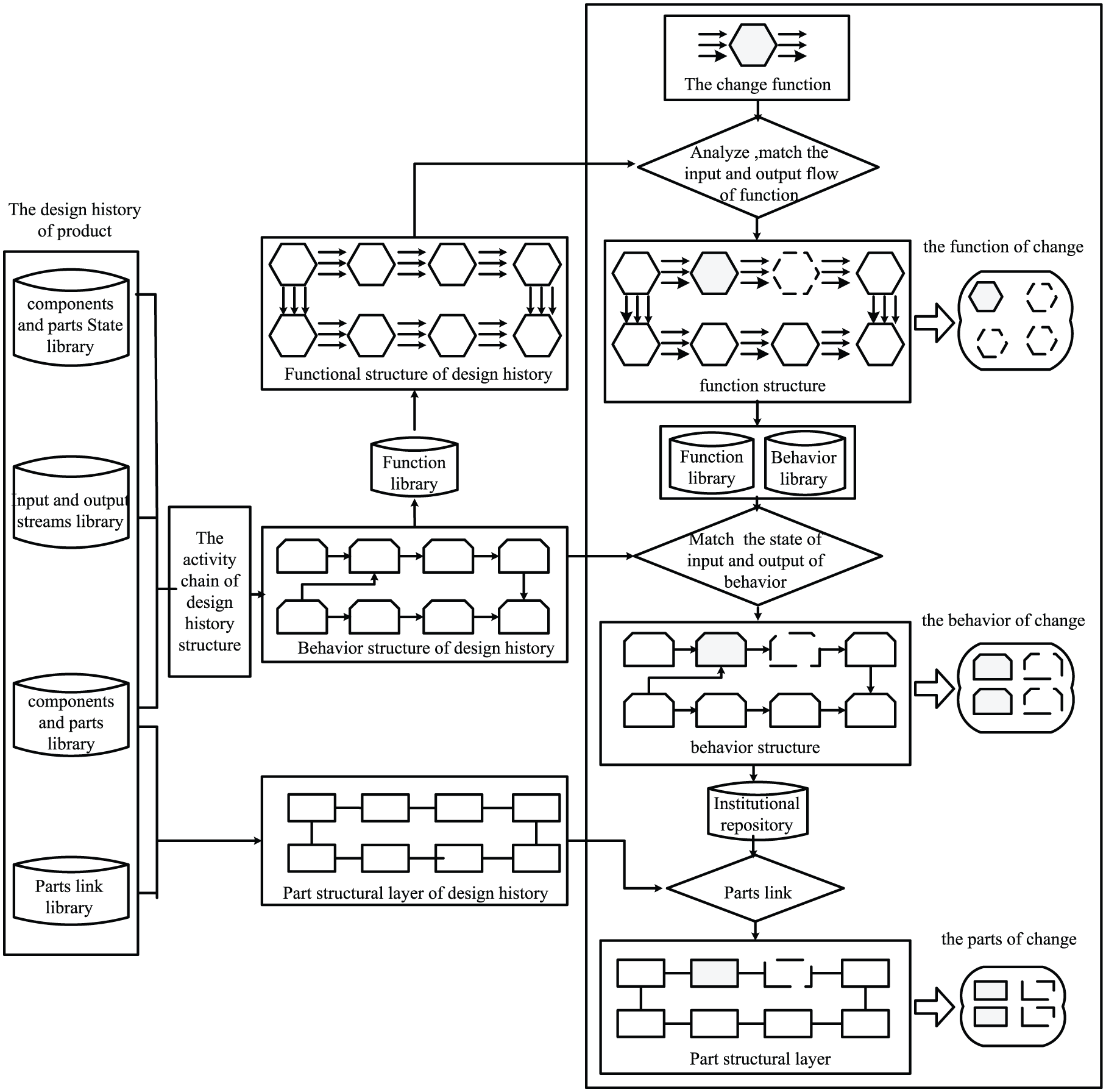
Propagation model of function change.
Function–behavior–structure model of product design history
The function–behavior–structure (FBS) model of product design history is the basis to analyze the propagation path of function change during conceptual design. Product design information history is classified and integrated to establish the FBS model of product design history inversely. This study suggests constructing a product behavioral process using product actions and then building a structure–function relationship using behavior (Figure 2). The FBS model of product design history includes the structural relationship of parts, behavior layer, and functional structure of products.

Design history information model.
Structural relationship of parts in design history
The structural relationship of parts describes the connection and assembly relationship among mechanical structures. This relationship expresses the topological structure of parts. The mechanical–structural relationship of products established from the connections among mechanical systems is shown in Figure 3. The quadrangle in Figure 3 represents the product structure and lines that connect the product structures that represent the connection and assembly relationships among parts.

Structural relationship of parts.
Behavior layer
Behavior refers to the action state changes of product parts in the function realization. Behavior can materialize function realization. Mechanical systems exchange substances, energies, and information mutually through various devices. These exchanges are mainly manifested by behavior transmissions of parts and are achieved through multiple behaviors. The action state of a product refers to the inherent properties of each structural element of a product. Action state represents the structural state at function implementation. Each structure of a product makes designed actions in the different system operation stages, but the action state of each structure changes differently as production operation continues. A structure has many action states, such as rotation, shrinkage, and straight movements. The construction steps of the behavior layer are as follows:
Step 1. The activity chain diagram of parts is constructed. First, parts are connected with action states using the deformed Petri network to obtain the action expressions of each part. The action states of the parts or shapes and locations of materials are changed under the effect of input/output streams. The activity chain diagram is constructed according to the order of actions (Figure 4). In Figure 4, p1, p2, p3, and p4 are the product structures, while A1, A2, A3, and A4 are the respective states of these product structures. Starting from the known part state, p1 produces the A1 action under the effect of input stream, whereas p2 makes the A2 action.
Step 2. The behavior chain is constructed. Behavior element is the minimum behavior unit, which only represents a single state of the part determined by structure + state. Behavior element is the specific state of each structure in function realization. One structure may produce several behavior elements under different input streams. Many behavior elements form one sub-behavior, and many sub-behaviors form one behavior. Based on the retrieval of common institutional repository, minimum behavior elements are integrated to set up a sub-behavior. For example, two behavior elements of gear rotation can be obtained by retrieving behavior library and by integrating into a sub-behavior of gear drive torque. In Figure 4, the behavior element of P1 under the input stream is P1A1.
Step 3. Static behavior is imported into the behavior chain. Static behavior refers to behavior with a constant action state during function realization. Static behavior is usually an imperceptible behavior that realizes functions through specific shape features. Material properties (e.g. stress and support force) are common static behaviors. Static behavior perfects the behavior layer; thus, the behavior layer becomes more complete. In Figure 4, static behavior is added into existing behavior according to connections between the part structures of static behavior and those of sub-behavior.

Behavior layer of products.
Functional structure
As an abstract expression of input–output transformational relation in the system, function is generally expressed by the input–output relationship of materials, energies, and signals. In product design, functional structure is combining sub-functions compatibly under the premise of overall function realization. 23 Function is expressed by verb + noun, such as input torque, display signal, transfer torque, and store energy. Input/output function streams are expressed by energy, material, and signal flows, such as speed, torque, force, voltage, current, and specific material.
Gero and Kannengiesser 24 have investigated input–output correlation according to changes in category, numerical value, quantity, location, and time. According to the division of Gero’s general function and based on the information stored in behavior elements, we have retrieved the function library to determine the functions of each behavior. The functional structure of product design history is established according to the logical relations of the behavior layer (Figure 5).

Functional structure of products.
Analysis on the propagation path of function change
After determining the functions that should be changed according to product demand, function change is reflected in the structural relationship of the parts. This occurrence is known as the propagation of function change (Figure 6). The propagation path of function change can be recognized through FBS mapping, input–output stream matching of functions, and inspecting the input–output state consistency of behavior layer.
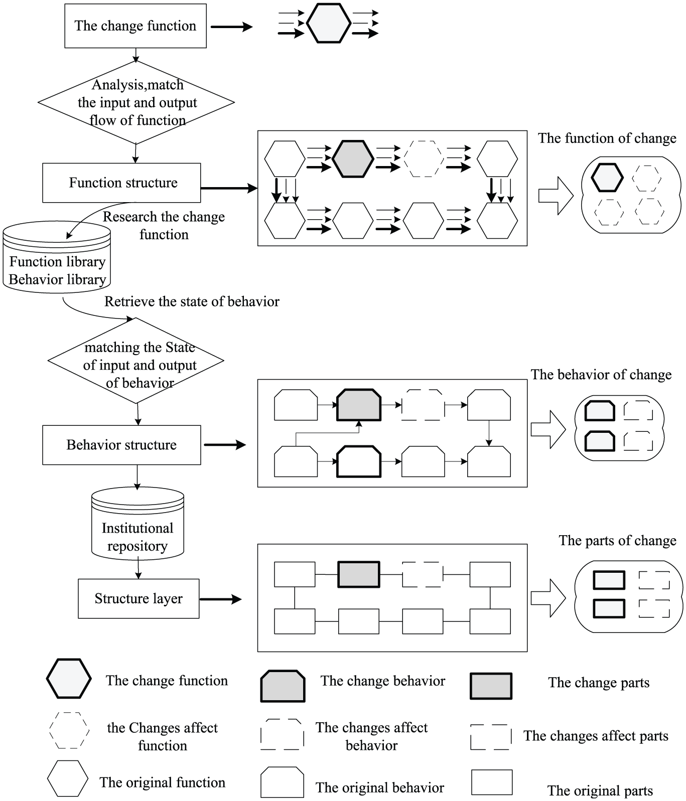
Propagation of function change.
Initialization of function change
Functional structure reveals logical relations and physical relations of functions. Series connection, parallel connection, and series–parallel connection of function elements are guaranteed order changes of input/output streams among different functions. Function change destroys the integrity of the original functional layer. Therefore, this study uses energy–physics–signal exchange relations of functions to protect the integrity of the functional layer. Function change is initialized through the following steps:
Step 1. Input/output stream parameters for function change are analyzed and determined whether these parameters are auxiliary functions.
Step 2. The function chain and positions of the changing function and the behavior and structures to change this function are determined in the established function change model.
Step 3. The specific operations of function change, such as adding, deleting, or changing, are determined.
Changes of functional structure
Functional structure involves three function changes: adding, deleting, and changing functions. If the changed function has the same input/output stream parameters with the original function, the function change does not change the other functions in the functional layer. If the input/output streams of the changed function cannot integrate with those of the original function, the changed function or the functional layer is modified accordingly to protect the integrity of the functional layer.
The changed functional structure can be solved according to the function analysis and specific operations of function change. The changed functions in the functional layer include both changed function and influenced functions. Changed function is the function whose operation has to be changed, whereas influenced functions are functions changed by the propagation of function change.
Adding functions
A product generally has various functions that can be divided into basic and auxiliary functions according to usage. Basic functions are indispensable efficiencies to meet some product demands. Such functions are directly related to the main goal of the product design. Auxiliary functions are secondary or additional functions of a product; such functions are designed to further perfect product functions and increase the characteristics of the product:
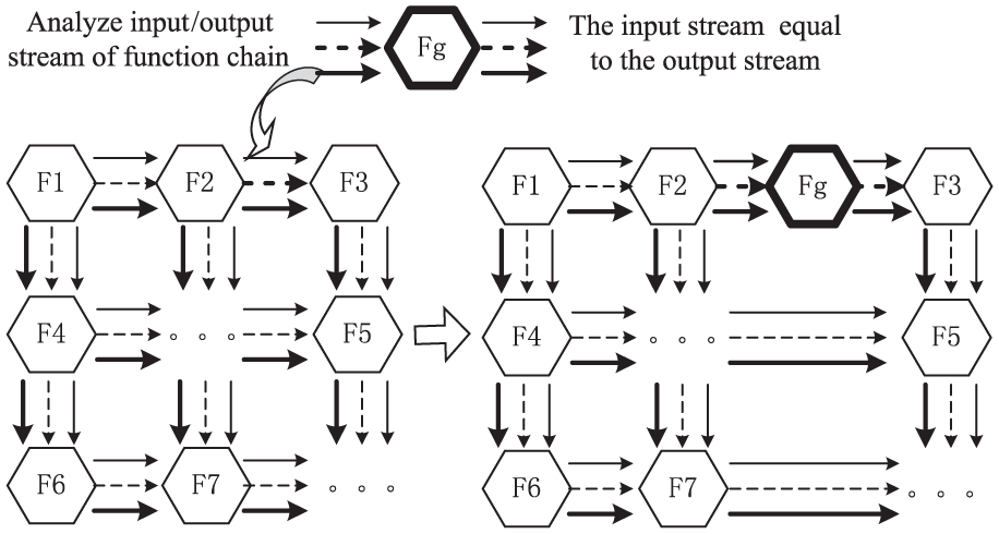
An added function has completely consistent input and output streams. In the functional structure, the added function with the same input/output parameters (e.g. both input and output of transfer torques are regarded as torques) can determine matching functional streams in the known functional chain and can be directly inserted to a corresponding position of the functional structure. For example, Fg in Figure 7 has similar input/output streams. Determining the functional chain where Fg should be added is primarily required to add Fg into the functional layer. Second, the functional stream should be determined to be completely consistent with the Fg input/output stream in the functional chain, and then, Fg should be inserted directly. Under this circumstance, function change would not spread around the whole functional layer.
An added function has partially matching input–output streams. If the input and output streams of an added function are different, the insertion point is determined by matching the input or output stream with the input/output streams in the functional structure. Moreover, other functions are changed according to actual situations to protect the integrity of the functional layer. For example, Fg in Figure 8 has different input and output streams. By matching the input stream with the functional layer in the figure, the insertion point is determined to be between P2 and P3. To maintain the integrity of the functional layer, F3 is changed after Fg is added to ensure that the input and output streams of F3 are consistent with the output stream of Fg and the input stream of F4, respectively. F4 is changed if the output stream of F3 cannot match with the input stream of F4. This process is repeated until the input and output streams of the functions match.
The added function has completely different input and output streams. If neither input stream nor output stream of the added function can match with the input/output streams in the functional structure, this function is determined as an auxiliary function. The insertion point for this auxiliary function is analyzed, and local functions are changed accordingly to realize the auxiliary function. For example, the efficiency of Fg in Figure 9 is analyzed first. The insertion point of Fg in the functional layer is found in F3. Next, F3 is changed to obtain the Fg output stream.
Addition of completely matching functions.

Addition of partial matching functions.

Added mismatching functions.
Deleting functions
Functional structure is an integral body. Function deletion maintains a reasonable logical relationship of the functional layer:
Functions are deleted directly. If a function has completely similar input and output streams, this function can be deleted directly without influencing other functions. The input stream of F3 (I3) in Figure 10 is equal to the output stream (O3) of F3. After F3 is deleted, the output stream of F2 (O2) becomes the input stream of F3 (I3). Therefore, other functions remain uninfluenced.
If the deleted function has different input and output streams, other functions should be changed accordingly to maintain the smooth circulation of functional streams in the functional layer. In Figure 11, the input stream of F3 (I3) is different from the output stream (O3) of F3. The input stream of F3 (I3) is the output stream of F2 (O2), while the output stream of F2 is the input stream of F4 (I4). If F3 is deleted, F3 and F4 should be changed according to the relationship between the input and output streams to maintain the smooth flow of the input and output streams.

Deletion of functions with similar input and output streams.

Deletion of functions with different input and output streams.
Changing functions
Function change is the replacement of the functional elements in the functional layer:
If the original function has similar input/output streams with the altered function, other functions in the functional layer remain uninfluenced.
If the original function has different input/output streams with the altered function, the other functions are influenced and those with input/output streams related to the altered function are changed accordingly. In Figure 12, F3 should be changed according to the function analysis. The input/output streams of Fg are different from those of F3. When replacing F3 with Fg, F2 and F4 are changed to make the output stream of F2 and the input stream of F4 equal to the input and output streams of Fg, respectively.

Changing functions with different input/output streams.
Calculation of function–behavior mapping
Function–behavior mapping is calculated after the change analysis of the functional structure. The behavior for function change is determined by retrieving the function library (Table 2) according to the name, input stream, and output stream of changed functions.
Function library.

Changes in the behavior layer
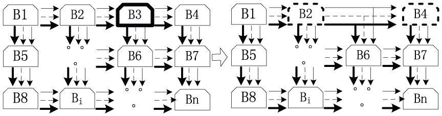
Function change can guide behavior changes through the function–behavior mapping relationship. Relations in the behavior layer are reflected by the input/output states of the behavior. The propagation terminal of behavior changes is determined based on the compatibility of the input and output states of the behavior. Behavior compatibility means that the output state of one behavior is consistent with the input state of the next behavior in the behavior chain. Behavior compatibility is the precondition of the behavior layer integrity. As shown in Figure 13, the output state of B1 is consistent with the input state of B2. The input/output states of the behavior are determined by retrieving the behavior library (Table 3). Changes in the behavior layer include adding, deleting, and changing behaviors.
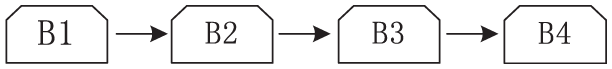
Behavior chain.
Behavior library.

Added behavior
If the input/output states of the function change behavior are compatible with those of the insertion point, adding this behavior would not influence the other behavior.
If the input state of the behavior for function change is incompatible with the output state of the behavior before the insertion point, and if the output state of the behavior is incompatible with the input state of the behavior after the insertion point, adding this behavior affects the other behavior. These two behaviors next to the insertion point are changed correspondingly. Based on Figure 14, F2 is realized by B2, and F3 is realized by B3. To change Fg, Bj would be added between B2 and B3. However, the input state of Bj is incompatible with the output state of B2, and the output state of Bj is incompatible with the input state of B3. Hence, other behaviors are required to match the input/output states. If no behavior exists in Fg which are compatible with the added Bj, B2 or B3 would be changed. B2 would be replaced by the available behavior of F2, and B3 would be replaced by the available behavior of F3. The behavior would be changed continuously until the whole behavior layer is compatible.

Added behavior with incompatible input/output states.
Deleting behavior
If a behavior has compatible input and output states, this behavior can be deleted directly. For example, both input and output states of the gear deceleration of speed change are axial rotations. After the function speed change is deleted, the behavior of gear deceleration can be deleted directly without influencing the other behavior in the behavior layer.
If a behavior has incompatible input and output states, deleting this behavior affects the other behavior. Therefore, the behavior surrounding the deleted behavior would be changed to maintain the compatibility of the behavior layer. In Figure 15, B3 would be deleted considering the function change. However, the input and output states of B3 are incompatible. Therefore, the output state of B2 is incompatible with the input state of B4. Hence, B2 and B4 would be changed to be compatible based on the retrieval results of the behavior library.
Deletion of behavior with incompatible input/output states.
Changing behavior
If a behavior can maintain similar input/output states after being changed, this behavior can be changed directly without influencing other behavior.
If a behavior cannot maintain the same input/output states after being changed, changing this behavior affects the related behavior. Therefore, related behavior shall be changed to make the input and output states of the whole behavior chain compatible. In Figure 16, B3 is changed into Bg. The input and output states of Bg are different from those of B3. Therefore, B4 would be changed subsequently to ensure that the input state of B4 is equal to the output state of B3. B4 is an influenced behavior.

Changing behavior with incompatible input/output states.
After the behavior layer is modified, the changed and influenced behaviors are determined and recorded in the behavior change list.
Changes in the structural relationship
The transmission and conversion of materials, energies, information, and movement behaviors in the mechanical system are finally reflected by the correlation among the mechanical structures. After determining the changed and influenced behaviors in the behavior layer, the structures of these behaviors are retrieved from the behavior–part library.
The retrieved parts in the structural layer are modified directly in the corresponding position in the structural relationship of parts according to behavior changes. In Figure 17, Pg should be changed. To obtain an excellent feature integration, P2 and P3 which are connected to Pg should be changed accordingly.

Changes in the structural relationship of parts.
In terms of the structural relationship of parts, the changed parts are divided into two classes according to the characteristics of changes:
Changed parts. These parts are used to add, delete, or change functions. Completely changed parts are redesigned fully according to changed functions and behavior, such as Pg. Changed parts have no historical information for reference.
Partially changed parts. These parts are connected with the completely changed parts in the structural layer, such as P1 and P2. Some features of partially changed parts can be acquired from the design history information of the product. However, features connected to the completely changed parts should be redesigned.
Changed and influenced parts are recorded in Table 4 of change propagation path. During continuous function changes, parts influenced by such function changes are determined and represented individually.
Behavior–part library.

Case study
Crushed ice is often used for food preservation. However, ice plants make ice blocks that still needs to be crushed. Existing monocular ice crushers 25 have a simple structure (Figure 18). To maintain an excellent fresh-care effect, different situations require various sizes of crushed ice. Therefore, ice crushers should be equipped with a size adjustment feature, except for ice crushing. This work has studied the function change of ice crushers to verify the feasibility of the propagation model of function change. Table 5 shows the main structure of monocular ice crusher.
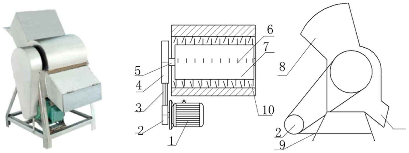
Structure of monocular ice crusher.
Design history of monocular ice crusher.

An ice crusher is composed of the following: (1) motor, (2) driving pulley, (3) trapezoidal belt, (4) driven pulley, (5) transmission shaft, (6) ice-crushing blades, (7) ice-crushing drum, (8) shell, (9) support frame, and (10) fence plate. The motor, driving pulley, and driven pulley cause the ice-crushing drum to rotate. The ice-crushing blades work with the fence plate in a spiral uniform. Ice blocks enter from the shell inlet and then slide down to the ice-crushing drum because of the dead load. The ice-crushing drum rotates counterclockwise at a constant speed, and the ice-crushing blades crush the ice blocks into crushed ice with uniform sizes. The crushed ice then slips off from the outlet:
The structural relationship of the monocular ice crusher parts is established according to the connections among these parts (Figure 19).
The energy and material flow chains of monocular ice crusher are created according to the energy, material, and signal flows in the design history. Next, the parts and states of these chains are combined in the behavior element chain. Subsequently, we retrieve the behavior library and then combine the behavior elements into the behavior chain. Finally, static behavior is added according to the connections to complete the behavioral structure of the monocular ice crusher (Figure 20).
Based on the behavior structure of the monocular ice crusher, we retrieve the function library to determine the functional structure of the ice crusher (Figure 21).
Size adjustment function is added into the original functional structure. According to the size adjustment analysis, the size of crushed ice can be controlled by adjusting the distance between the fence plate and the ice-crushing drum. Both input and output streams of adjust distance are crushed ice. Next, the matching input/output streams in the functional layer are searched (Figure 22).
The insertion point in the behavior layer is determined according to changes in the functional structure, and the corresponding behavior is retrieved from the function library. An ice crusher is similar to a stone crusher and a coal crusher. A jaw crusher can adjust sizes of stone crushes by changing the distance between the fixed jaw and the movable jaw. Therefore, the size of crushed ice can be controlled by adjusting similar distances in the ice crusher. Particularly, the static behavior of the fence plate should be changed for the fence plate to become movable. The corresponding behavior structure is shown in Figure 23.
The change in the behavior layer is mapped onto the structural layer. The structural relationship of parts is rebuilt by retrieving the behavior–part library to implement such behavior change. The parts that should be changed are determined based on this library (Figure 24).
A new ice crusher is designed according to the changes in the behavior layer and the structural relationship of the parts (Figure 25). The new ice crusher design is composed of the following: (1) ice block, (2) shell, (3) ice-crushing blades, (4) ice-crushing drum, (5) fence plate, (6) adjustment lever, and (7) adjustment pin. According to the new structural relationship of the parts, the adjustment lever and adjustment pin are completely changed parts, whereas the fence plate is an influenced part.
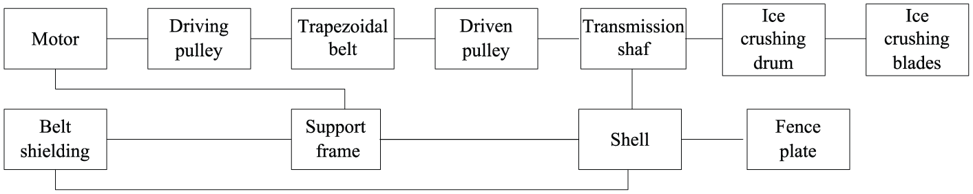
Structural relationship of monocular ice crusher parts.

Behavior structure of the monocular ice crusher.

Functional structure of monocular ice crusher.

Change in the functional structure.

Behavior structure of monocular ice crusher with size adjustment function.

Changed structural relationship of parts.
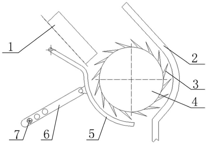
New ice crusher design.
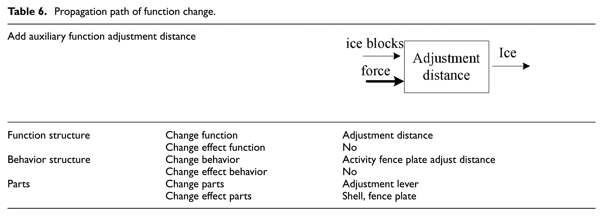
The adjust distance is implemented through the movable fence plate. The input and output streams of the functional layer are still compatible after the adjust distance is added, which does not influence the other functions. The input and output states of the behavior layer remain compatible after the distances of the fence plate are adjusted, which does not influence the other behaviors. In the structural layer, the adjustment lever is a completely changed part. In contrast, a fence plate and a shell exist in the original design, and only some changes are required. The original features of the rest of the parts can be maintained. The propagation path of the function change is shown in Table 6. Based on the analysis of the function changes during conceptual design, further perfecting parts that may be changed is focused on, but the rest of the parts can use original designs. Using original designs can increase the product design efficiency significantly.
Propagation path of function change.

Also, a prototype system for conceptual design–oriented function change propagation solving is built based on VB.net and SQL Server2000 (Figures 26 and 27). This prototype system can assist designers to predict and analyze the impact of functional changes on the product in the design stage. Solution results of monocular ice crushers show validity of the proposed model.

Conceptual design–oriented function change propagation solving prototype system.

Solution results of monocular ice crushers.
Conclusion
Based on the input/output streams of the functions and the input/output states of the behavior in the propagation model of function change, the propagation path of function change during conceptual design is analyzed. It suggests constructing behavior elements from the action states of the parts and analyzing the integrity of the behavior layer based on the input/output state consistency of the behavior. First, after the FBS model of the product design history is established, functions are added, deleted, or changed. Influenced functions are determined according to the input/output streams of the functions. Second, behaviors are added, deleted, or changed based on the function–behavior mapping relation. Influenced behaviors are identified by analyzing the input/output state consistency among the behaviors. Third, the structural relationship of parts is changed according to behavior changes. Through the function change analysis based on the propagation model of function change, the propagation path of function change can be determined and predicted.
Compared with the existing methods (as shown in Table 1), the advantage of the proposed method in this article is that it can support product conceptual design. The insertion and deletion operations of the function change are realized through the matching of the input and output flows. The method is able to assist designers to predict and analyze the impact of functional changes on the product in the design stage.
To provide more effective design references, future research will focus on perfecting the function library, behavior library, and behavior–part library for the propagation model of function change.
Footnotes
Academic Editor: Teen-Hang Meen
Declaration of conflicting interests
The author(s) declared no potential conflicts of interest with respect to the research, authorship, and/or publication of this article.
Funding
The author(s) disclosed receipt of the following financial support for the research, authorship, and/or publication of this article: This research work was supported by the National Natural Science Foundation of China (51375451).