
Abstract
With more axles for multi-axle vehicles, conventional steering trapeziums are unable to let every tire fit Ackermann steering which cause tire wear increasingly more serious. To alleviate this problem, an original mechanic-hydraulic servo steering system with a controllable tie rod is designed. By controlling the angle of one wheel and the length of tie rod, both wheels can be controlled as per default trajectory which implemented Ackermann steering. This article utilized mechanic-hydraulic servo feedback to design a mechanic-hydraulic servo valve which controlled the tie rod accurately. It ensured dynamic characteristics of steering wheels and driving force. To understand inherent characteristics of system, the mathematical model was established. The transfer function was derived, and this high-order system was reduced by Routh approximation. Analyzed natural frequency and the main parameter (the gain coefficient of displacement) which influences the dynamic characteristics had been found out. Analysis shows that the lower the gain coefficient, the higher the speed of response. Moreover, the accurate simulation model of servo system is built on AMESim. Contrasting five groups of simulation results, it is obtained that the influence rule of the gain coefficient is consistent with theoretical analysis. This research provides a useful reference for future nonlinear control.
Introduction
Multi-axle vehicles have been widely used in infrastructure, heavy industry, military equipment, and other fields, such as the large crane, mining vehicles, and missile transporter vehicle. Steering performance of multi-axle vehicles is an important capability index because it has direct effect on vehicle agility, manipulate stability, and use economy. Steering trapezoid mechanism has been used in most of the steering systems, but the inherent defects of four-bar linkage can only fully meet Ackermann principle on one side of Ackermann steering; on the other side, tire cannot do pure rolling. So the tire wear is a serious problem.
In recent years, pure rolling of multi-axle vehicle has been widely discussed. For example, S Pramanik 1 designed a kinematic synthesis of a six-member mechanism for automotive steering, it has high precision and the range of steering angle is limited by structure. J-S Zhao et al.2,3 used noncircular gears to design a kind of steering mechanism, it made use of noncircular gear engagement to properly distribute steering angle. Yunchao Wang et al. 4 established a 3-degree-of-freedom (DOF) multi-axle steering vehicle model using Lagrangian analysis method which can offer helps to others in multi-axle steering research. Xiachun Huang 5 modified steering trapezoid mechanism by adding length adjustment device (nut, spout, or cam); the length of lateral connecting rod is variable.
All of these studies achieved pure rolling by improving steering mechanism. However, structure improvement is not very superior in regulatory, regulatory, saving space. There is still room for further refinement. Meanwhile, for heavy vehicles, its steering load is bigger (especially the pivot steering resistance moment is great). If the plan is purely dependent on the optimization of mechanical structure, it is difficult to achieve high-precision steering control under overload condition. And electro-hydraulic control is small size-to-power ratios, high response, high stiffness, and high load capability, 6 which combines the dynamic performance of hydraulic and the flexibility electronic control. Electro-hydraulic control technology is applied to conventional steering system, which is based on satisfying pure rolling kinematic relations by mechanism design; system obtains large torque and high response by utilizing electro-hydraulic serve to control hydraulic actuator. Hence, the steering system of heavy vehicle can realize high-precision pure roll through the combination of machinery, hydraulic and control, and the performance of steering system is improved obviously.
This comprehensive drive control actually belongs to the hydraulic servo system. If the traditional linear control is applied in hydraulic systems, it is difficult to attain eminent control characteristics because of highly nonlinear of hydraulic. And researchers usually design nonlinear controller to obtain high precision and high response. At present, the nonlinear control strategy has been widely applied in hydraulic servo system. For example, Janne Koivumäki 7 presented the Cartesian free-space control of hydraulic manipulators based on the virtual decomposition control and the experiments proved that the control strategy improved the control performance. Salvatore Strano 8 designed an SDRE-based tracking control for a hydraulic actuator which contained a feedback term based on the state-dependent Riccati equation (SDRE) technique and a feed forward term obtained by the system dynamics inversion. In addition, hydraulic servo system is affected by the external load disturbance and model uncertainty. 9 Based on Fourier series approximation, Jianyong Yao 10 proposed a practical nonlinear adaptive repetitive controller for motion control of hydraulic servomechanisms to compensate the periodic modeling uncertainties. This controller has lower noise sensitivity and less memory requirement. And there are other different nonlinear control strategies, such as robust control, 11 adaptive control,12,13 and adaptive robust control.14,15
The above results show that the performance of hydraulic serve system which used nonlinear control strategy is much better than systems that used linear control strategy. And nonlinear control can restrain interference and compensate the error of model uncertainty which is not achieved by linear control. However, nonlinear control methods mainly focus on the stabilization and tracking problem and are unable to further ascertain the inner characteristics of systems. The inner characteristics are internal physical properties, such as inherent frequency and damping ratio, which determine the performance limit of the control system. Therefore, utilizing classical control theory to analyze the characteristics of the system can set foundation and provide the important reference for the future accurate nonlinear control. Several steering electro-hydraulic servo systems are involved in this article, and their mathematical models are all higher order system (order ≥ 5). Classical control theory cannot be used to analyze their properties directly, but it can obtain their properties after doing model reduction. For the steering system, they also require that stability is ensured and low-frequency characteristics need not be changed after reducing order. Among the numerous order reduction methods,16–19 Routh approximation is suitable for a transfer function with unknown parameters and can keep the stability and the low-frequency characteristics of the system.
Therefore, this paper is based on the above-mentioned research frame. Firstly, combined with mechanical optimization design and electro-hydraulic control, a new mechanical-hydraulic servo valve is designed. It guarantees pure roll steering by through direct position servo control. Then, its mathematical model is established and the system transfer function is obtained based on the classical control theory. After that, the transfer function is simplified by Routh approximation. Finally, it is concluded that the key parameters affect the control characteristics and rules of influence are discussed. This article sets a foundation for subsequent parameters optimization design and provides the reference for the future electro-hydraulic servo nonlinear control based on pure rolling.
The principle of steering system for pure rolling
The traditional steering systems of multi-axle vehicle adopt steering trapezoidal mechanism for driving as shown in Figure 1. But there is only one degree of freedom in steering trapezoidal mechanism which can guarantee only one steering angle is the same as target angle. And the other steering angle can only be fitted by steering trapezoidal mechanism which makes both the wheels meet Ackermann conditions as far as possible. Obviously, the traditional steering trapezoidal mechanism cannot strictly achieve both sides pure rolling.
The sketch of steering mechanism.
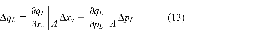
Aimed at the above disadvantage, if the tie rod is adjustable, that is, its length can be changed, both steering angles would be controlled. We can calculate both angles
In order to make wheels meet Ackermann conditions, this article presents a new type of steering system for pure rolling. The design of this system mainly includes the hydraulic principle and hydraulic components. The design of hydraulic principle: first, system drives one wheel steering and changes the length of lateral connecting rod; then, the signal of length is fed back to control valve, so mechanic-hydraulic servo steering system (MHSSS) for pure rolling has the characteristic of mechanic-hydraulic servo; through accurately controlling the rod length so as to accurately control the angle of the other wheel. The design of hydraulic component: to achieve the above functions, design a new type tie rod and mechanical-hydraulic servo valve; the tie rod is a telescopic cylinder which has feedback fluid chambers. Mechanic-hydraulic servo valve is combined with cam structure which can change the signal of steering angle to the displacement of valve element. The two hydraulic components are the core components of the system. And both of them are closely related. According to different vehicle models design a tie rod and then design the control valve based on the parameter of the tie rod.
Hydraulic principle of MHSSS
MHSSS mainly includes the switch valve, relief valve, check valve, tie rod, and mechanic-hydraulic servo valve, which are shown in Figure 2. The tie rod is servo controlled by mechanic-hydraulic servo valve so that effective guarantee that left and right wheels can meet Ackermann principle. The high-precision dynamic pure roll of vehicle is realized by the feedback between the tie rod with control valve. In addition, there are machining error and wear in the telescopic cylinder. Thus, internal leakage and external leakage are inevitable in the cylinder. And the control precision of tie rod is reducing with the accumulation of leakage. In order to improve the accuracy and eliminate the generation of negative pressure, we design oil-addition circuit which includes switch valve, pressure reducing valve, and check valve.

Schematic diagram of steering hydraulic system: 1, hydraulic oil tank; 2, pump; 3, switch valve; 4, reducing valve; 5, check valve; 6, wheel; 7, tie rod; 8, mechanic-hydraulic servo valve; and 9, relief valve.
Steering condition: first vehicle steering signal is transferred to mechanic-hydraulic servo valve and then valve control the length of tie rod which command the angle of wheel. Feedback fluid chambers of tie rod send feedback signal to feedback fluid chambers of servo valve when the length of tie rod is changing and then reduce the relative displacement of servo valve that has a tendency to end working. Thereby the output displacement can follow the input signal.
Filling oil condition: the switch valve is a two-way reversing valve which is normally closed. Cam makes switch valve turn on state when the vehicle is not steering. And then system feedback chambers are compensated with the high pressure oil sequentially flowing from a pressure reducing valve and a check valve. The system fills oil one time when the servo valve is in the median. So the system can reduce the error caused by the closed chamber and eliminate the negative pressure.
The design of mechanic-hydraulic servo valve
Mechanic-hydraulic servo valve is a key component of MHSSS. It is a four-way mechanic-hydraulic reversing valve whose structure is shown in Figure 3. The servo valve is different from other ordinary servo valves because of the cam mechanism, and cam curve is the key to drive the servo valve. Cam mechanism changes the rotary motion of steering wheel to the reciprocating motion of valve element and then control the servo valve to open or close. In other words, the change of steering angle can directly control the length of tie rod. The valve can remove the disturbance which is caused by electrical system fault, so improve the reliability of multi-axis vehicle steering. What’s more, the segmented cam curve used in the mechanical-hydraulic servo control device can make the tie rod telescopic hydraulic cylinder locked in a corresponding position, which guarantees the pure rolling steering performance and simultaneously reduces the risk in high speed driving.

The structure drawing of mechanic-hydraulic servo valve: 1, cam; 2, valve element; 3, valve pocket; and 4, valve body.
As shown below, the servo valve has three-layer structure: valve element, valve pocket, and valve body. The valve element is pushed to the right by the left spring when cam spins clockwise. And high pressure oil flows into the left chamber of tie rod through port P and port B. At this time, the left chamber becomes a high pressure chamber which pushes the piston of tie rod to the right. The hydraulic oil of right chamber flows back to the fuel tank through port A and port
As we know, servo valves have good response characteristics. How does the mechanic-hydraulic servo valve we designed achieve the servo? As shown in Figure 4, both the tie rod and servo valve have feedback cavities. The left feedback cavity of tie rod and the right feedback cavity of servo valve are connected together by a pipe. Two other feedback cavities are also connected together. When the valve receives a steering signal, it executes actions immediately. Then, the cylinder performs the operation. At the same time, feedback cavity sends feedback signal to valve and the steering signal is decreasing continuously. The valve will be closed straight away, once the signal reaches zero. Thus, this hydraulic valve has good response characteristics.

Simplified physical model.
The modeling of MHSSS
The tie rod and servo valve need to be modeled and analyzed, getting the influence of the key parameters to the performance, and providing theoretical reference for subsequent actual design, because they are new parts of MHSSS.
As shown in Figure 2, system has two important and special components: the tie rod and mechanical-hydraulic servo valve. The tie rod is connected with the valve by feedback circuit, so it cannot be separately processed in modeling and greatly increases the difficulty of modeling. The mathematics model of valve control cylinder is common; the most difficulty of modeling is to change the model of valve control cylinder which is an open-loop system to a close-loop system based on feedback circuit.20,21 They meet the energy conservation that is the outflow rate of tie rod’s feedback cavity is equal to the inflow rate of control valve’s feedback cavity and vice versa. Therefore, establish the relationship of the output displacement and the input signal by flow continuity equations. Meanwhile, the effects of feedback cavity should be considered in the stress analysis.
Simplify model
MHSSS is a very complex system in Figure 2. It is very difficult to achieve the mathematical modeling directly. Therefore, the complex model in Figure 2 is simplified as a simple physical model in Figure 4. The simplified model keeps the important parameters of the system and clearly shows the connection between the various physical quantities, which greatly reduce the difficulty of modeling and also assist later theoretical analysis.
Basic equation
Mathematical modeling is built according to the model in Figure 4. Set modeling condition and ignore the secondary factor before modeling, and they can reduce the difficulty of modeling.22,23
Modeling condition:
The pipes which connect valve with hydraulic cylinder are symmetrical, short, and thick;
The pipeline pressure loss and the dynamics of pipeline can be ignored;
Each pressure of hydraulic cylinder’s work cavity is equal everywhere;
Oil temperature and bulk modulus of elasticity are constant;
Regardless of the hydraulic cylinder of internal and external leakage;
Several fundamental equations based on the above modeling conditions can be obtained.
The force balance equation of the tie rod
The force balance equation of the servo valve

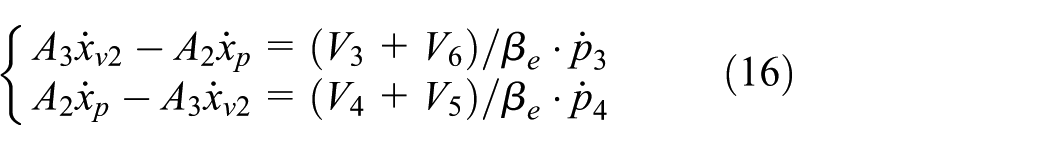
Flow continuity equations of the tie rod

Flow continuity equations of the servo valve
Equations of orifice outflow

Simultaneous equations (2)–(6)

Simplify equations
There are so many equations and nonlinear equations in equation (7), and it is hard to calculate transfer function. Therefore, equations should be consolidated and simplified based on the relationship between the various physical quantities. And the nonlinear equations are linearized.
The servo valve is a zero opening and four-way valve in this system

Combined with equation (4)

And

So equation (9) can be simplified to

Rearranging equation (6) presents

Equation (11) is nonlinear, and doing Taylor series expansion at point

The higher order infinitesimal of expansion (12) is ignored
And

And hence equation (11) can be simplified to

There are conclusions that
There is a new equation
where

Equation (16) is a nonlinear equation and can be linearized by neglecting
Rearranging equation (16) presents

So equation (7) can be simplified to

Simplifying equations can significantly reduce the number of equations which all equations are linear, and they ensure that the system transfer function can be solved.
Transfer function
To do Laplace transform according to equation (19)

The block diagram can be drawn based on equation (20).
Figure 5 expresses this system has two inputs. Because

where

The block diagram of system.
Rearranging equation (21) presents

where
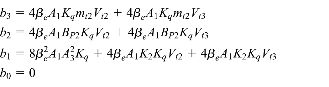

In order to simplify the transfer function, equation (22) ignores the influence of
And hence

The order reduction and characteristic analysis of system based on Routh approximation and simulation
According to equation (22), the transfer function is a higher order system whose coefficients are complex. And high-order system is difficult to directly analyze its characteristics, so they need to be reduced order before analysis. The methods of reducing order are many, selecting different methods according to different requirements. There are many ways to reduce order, such as predominant pole, Padé approximation, and Routh approximation. The method of predominant pole which calculates all pole of the transfer function is suitable for the analysis of the exact high-order system; 17 Padé approximation 18 can cause the system to appear instable, so this article simplify transfer function by Routh approximation 19 which can reserve the low-frequency characteristic and stability. And it can provide the beneficial reference to design and analyze multi-axle vehicles for pure rolling. For the steering system, its stability and low-frequency characteristics cannot be changed after the order reduction. Thus, this article uses the Routh approximation method; the Routh approximation is suitable for a transfer function with unknown parameters and can keep the stability and the low-frequency characteristics of the system.
System order reduction
If H(s) is the transfer function of an asymptotically stable system, then each Routh approximant is asymptotically stable. 24 As a system, its stability just depends on the denominator of transfer function. Routh approximation first determines the denominator of reduced transfer function which is computed by Routh table as shown in Table 1. And the new denominator can keep the stability of system. The process of proof is introduced clearly in Zou et al. 25

In Routh approximation, the Routh convergent is an approximation to H(s) which tends to preserve high-frequency behavior.
24
However, for the practical applications of control system, the most importance of them is the performance of low frequency area, so makes use of a transfer function


It is merely the operation of reversing the order of the polynomial coefficients. After doing above transformation,
Parameters

Equation (24) is changed to the second-order Routh approximate

And

So

Rearranging equation (26) presents

Characteristic analysis
Equation (27) can be rearranged to a general form as

And

Assume
Rearranging equation (29) presents
Due to
Hence
Due to
Hence
Due to
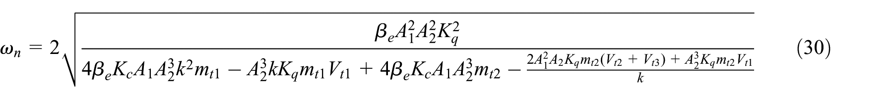
Hence
Rearranging equation (30) presents

Now proving that
Due to
And
Due to
And
Due to
And
Assuming
Due to
And
Hence
According to the change rule of
In conclusion,
Simulation on AMESim
In the above theoretical analysis, do more linear simplification and approximation processing. In order to obtain an accurate model that can be using to guide practice, build a simulation model on AMESim as shown in Figure 6.26,27
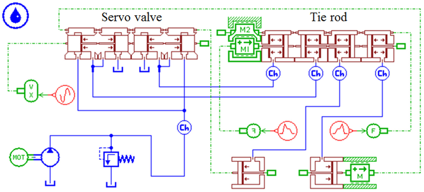
Simulation model.
Its main parameters are shown in Table 2.
Main parameters.

According to Table 2,
As shown in Figures 7 and 8, the displacement of tie rod is controlled without overshoot, tracking error is among

Aim curve and simulated curve of output displacement.

Tracking error curve.
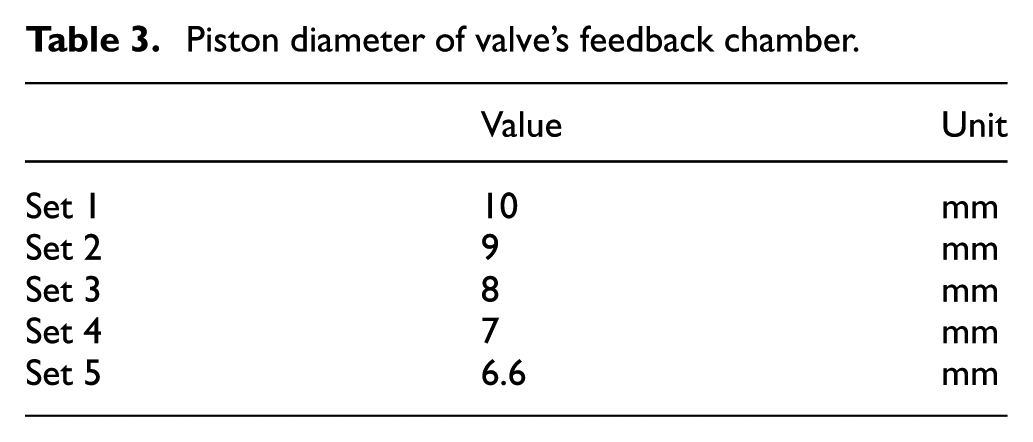
Piston diameter of valve’s feedback chamber.
Different curves of output displacement were obtained under different parameters by batch running of AMESim. And the results are as shown in below figures.
According to Figures 9 and 10, displacement amplitude of tie rod is increasing with increasing k, and the position of passing zero point is further away from expected passing zero point that is the response speed coming down.

Curves of output displacement.
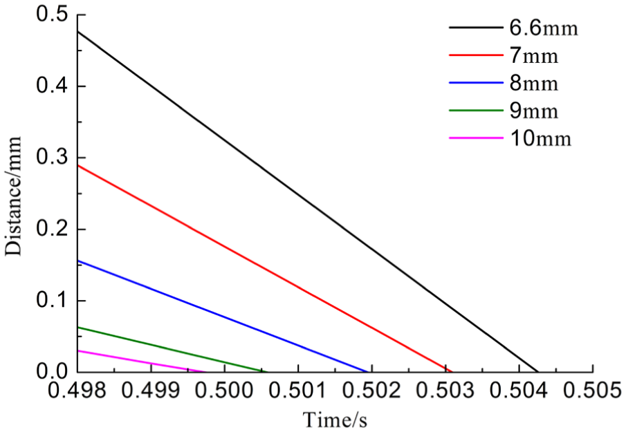
Magnification of passing through zero point.
Conclusion
This article puts forward a type of MHSSS which contents a new type of servo valve combined with cam structure to realize the precise control of steering angle; it reduces tire wear by satisfying the needs of Ackermann turning geometry.
The mathematical model of the part steering system is set up; the influence of gain coefficient for the system response speed is understood. The results show that the Routh approximation can effectively handle control system transfer function problem which is high order and do not break the low-frequency characteristics; the natural frequency of the steering system is inversely proportional to the gain coefficient, and the natural frequency limits the response speed, thus the response speed of system is inversely proportional to the gain coefficient.
A simulation model of steering system is built to prove the results of theoretical analysis. Results show that tie rod has good tracking characteristics and the tracking error is small and not overshoot. Verify the system response speed is inversely proportional to the gain coefficient.
Footnotes
Appendix 1
Academic Editor: Zheng Chen
Declaration of conflicting interests
The author(s) declared no potential conflicts of interest with respect to the research, authorship, and/or publication of this article.
Funding
The author(s) disclosed receipt of the following financial support for the research, authorship, and/or publication of this article: This research was financially supported by the National Natural Science Foundation of China (No. 51405084) and Educational commission of Fujian Province, China (No. JA13051) through Multi-actuator driving and electro-hydraulic servo control with novel metamorphic trapezoid achieving pure rolling steering in multi-axle vehicles.