
Abstract
Many multi-axle applications use electro-hydraulic control systems with proportional valves. The proportional steering system can satisfy common engineering requirements, but it is likely to fail if the steering angle or load changes drastically because of poor dynamic characteristics, including dead zones, hysteresis, and frequency response. An electro-hydraulic servo steering system with servo solenoid valve is proposed to guarantee a precise dynamic response and good price–performance ratio of the closed-loop system. A co-simulation model based on ADAMS and AMESim was established to analyze the influence of the main parameters on steering performance. The mechanical model includes tire and ground parts, and the steering load can be simulated accurately. The simulation results show that dead zones, hysteresis, and frequency response of control valve have great influence on the steering performance, and the servo solenoid valve is proper for this system. The servo steering system was applied to the actual seven-axle all-terrain crane, and the system performance was extensively tested. The experiment results show that the system has good accuracy and tracking response performance in several real situations, including parking and high-speed transport.
Introduction
Multi-axle vehicles have been widely used in the fields of industrial equipment, such as large machine parts installation and bridge.1,2 Their competitiveness arises from well-known advantages of good trafficability and maneuverability. The multi-axle steering system is one of the core components for multi-axle vehicles, particularly for all-terrain cranes and transporting girders. Multi-axle steering performance directly determines the maneuverability at low speed and handling stability at high speed and has become an important indicator to measure the development level of large vehicles.
The steering system includes a variety of structural types, such as mechanical, hydraulic, electronic, and electro-hydraulic power steering systems (EHPSS).3–5 Mechanical and conventional hydraulic steering systems are unable to meet the requirements of flexibility and stability in multi-axle vehicles very well. Electronic power steering systems cannot effectively control large loads in heavy vehicles due to their relatively small driving power. EHPSSs are a combination of traditional hydraulic power steering system with modern electronics and allow using fluid drives in the most demanding applications, that is, good drive capacity with large loads and the flexibility of electronic controlling. Therefore, EHPSSs are widely used for large multi-axle vehicles, guaranteeing maneuverability and stability.
The superior dynamic behavior of the electro-hydraulic power system is determined by the valve controller performance, such as frequency response and tracking accuracy. However, proportional valve control, applied in the vast majority of EHPSSs, has insufficient dynamic responses for sudden direction changes with large angles.
The pursuit of high steering performance is an unending demand. Since the late 1990s, EHPSS research has had wide attention worldwide.6–8 There are two common hydraulic driving types: single-acting or double-acting cylinders. Haggag et al. 9 designed, modeled, and tested an electro-hydraulic steer by wire system, which included a solenoid-controlled two-stage proportional control valve and a pair of single-acting hydraulic cylinders, for an articulated vehicle, achieving proportional control characteristics. Kemmetmüeller et al. 5 proposed a novel electro-hydraulic closed-center power steering system with a double-acting cylinder and two proportional steering valves, and a nonlinear controller was designed to simultaneously meet the demands for high dynamic performance and energy efficiency.
Many engineering solutions have been proposed for multi-axle steering applications. Zhao et al. 10 utilized an electro-hydraulic proportional control system to obtain coordinated steering for the TLC900 girder transport vehicle used for constructing high-speed railroads. Li et al. 11 proposed a network control steering system with proportional valves for large-scale transportation vehicles to achieve smooth and accurate steering motion without slipping or sliding. Tian et al. 12 used a similar electro-hydraulic proportional steering system for elevated platform trucks.
A generalized model has also been developed to produce dynamic equations of motion for vehicles with an arbitrary number of steerable and non-steerable axles. 1 Many control strategies have been studied to improve maneuverability and stability, such as zero vehicle sideslip angle dispatching control, H2/H∞ optimization control, and adaptive robust control.13–19 These multi-axle steering systems can achieve better performance than conventional hydraulic power steering system. However, all these steering systems use proportional valves in the hydraulic control systems, and proportional components limit steering performance due to poor inherent characteristics, such as dead zones, hysteresis, and frequency response.
Single-axle performance is a key determinant of multi-axle steering systems. Consequently, the higher demand for more precise, more rapid, and easily implemented EHPSS is a strong motivation for investigating multi-axle steering.
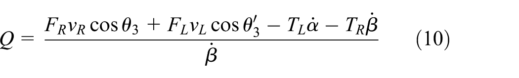
In this article, a new system incorporating a servo solenoid valve, called electro-hydraulic servo steering system (EHSSS), is proposed, where the control valve directly drives two hydraulic actuators precisely and quickly. Compared to proportional valves, the servo solenoid valve has many advantages: no dead zone, higher frequency response, and smaller hysteresis. 20 It also has lower pollution requirements and higher price–performance ratio in comparison with servo valve. Thus, the adoption of servo solenoid valves supports superior EHSSS performance. However, the optimal choice of design structure and control parameters remains problematic because of the complicated models required (mechanical, hydraulic, control, and tire–ground loading). Therefore, extensive simulations and experiments were performed to identify suitable parameters and verify the performance of the proposed EHSSS, particularly for complex road conditions with frequent steering changes, where the input steering command produces sudden changes, and for motion control of single-axle steering systems in multi-axle vehicles.
Working profile of the EHSSS
EHSSS design
To balance maneuverability at low speed and handling stability at high speed, mechanical–hydraulic steering systems usually use the front axles, whereas EHSSS is typically applied to the rear axles. A particular example is the seven-axle all-terrain crane, including three front axles with mechanical–hydraulic steering system and four rear axles with EHSSS. Thus, vehicle safety can be guaranteed by the front axles, and dynamic steering characteristics can be improved by EHSSS on the rear axles. In this article, the seventh axle was selected as the research object, and the dynamic characteristics were studied.
Function
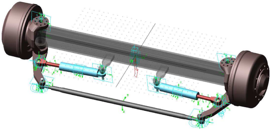
Unlike traditional passenger cars, heavy vehicles utilize the trapezoidal steering mechanism, including a dual actuator, as shown in Figure 1. The dual actuator has the advantage of greater driving power, which is essential for heavy vehicles, for example, the all-terrain crane in Figure 1 weighs 84 tons, each of the seven axles bearing (nominally) 12 tons. It is essential to use electro-hydraulic steering systems to guarantee driving capacity and tuning performance.
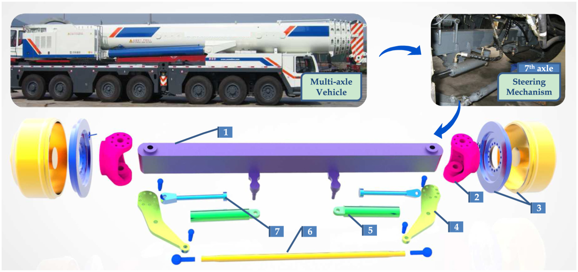
Multi-axle steering vehicle and diagram of the steering mechanism.
Therefore, we designed the hydraulic steering system, as shown in Figure 2, with several functions, including servo steering, hydraulic lock, emergency manual operation, and overload protection: 21
Servo steering. In Figure 2, the servo solenoid valve 1 is the key component to control the steering system, and its characteristics determine the system dynamic performance. When steering, directional valve 3 is in the normal position to allow pilot check valves 4 and 5 bidirectional operation, and valve 2 is also in the normal position. Relief valves 6 and 7 are safety valves. Valve 1 could be a proportional, servo solenoid, or servo valve. We have discussed the choice of valve type below. Valve 1 is adjusted by a closed-loop control system according to the steering error between command and actual angles, measured by the angle sensor. Thus, the steering wheels can be controlled accurately by the system.
Hydraulic lock. The wheels should be locked at their required positions in steering mode. For example, the middle rear axle in heavy vehicles should be locked to prevent the vehicle from going into a snap. For this case, valve 3 is energized to make valves 4 and 5 check the oil from the cylinders, while the valve is power-off to make valves 4 and 5 open. So, valve 3 controls whether the hydraulic cylinders should be locked.
Emergency manual operation. It is dangerous to continue driving when the rear axles are in the wrong position due to failed electronic control; for example, if valve 1 is out of control, the servo steering system cannot operate. In this case, emergency manual operation is useful. Directional valve 2 can be used to move the wheels left or right by manual operation. The wheels on each axle can be regulated easily and smoothly and then locked in their correct position. This is convenient to move the vehicle for maintenance or roadside repair at very low speed. This function is very effective in actual use.
Overload protection. Relief valves 6 and 7 are installed to avoid damage from high pressure impact.

Electro-hydraulic servo steering system for a single axle.
Control system
To guarantee good steering performance, heavy vehicles also need an appropriate control system. We designed the EHSSS control system as shown in Figure 3. The control system consists of two sections: command generation and closed-loop control, including power oil source, steering trapezoidal mechanism, servo steering controller, programmable logic controller (PLC), angle and vehicle speed sensor, and so on.

Electro-hydraulic servo steering system control.
The control system operates as follows:
The angle sensors (component 10 in Figure 2) for each axle acquire the actual steering angles. The target steering angles are determined in the PLC using the Ackerman geometry principle, according to the angle of the steering wheel, front axles, vehicle speed, and steering model.
The target and feedback angles are transmitted to the servo steering controller, and the error between them is calculated. The servo solenoid valve (component 1 in Figure 2) for each axle is adjusted by the controller according to the calculated error. High-pressure oil flows into the steering cylinder, and wheels are turned by the two actuators through the trapezium mechanism. The steering angle is continuously modified until the error is zero, establishing the closed-loop control system.
The dynamic control process operates at high frequency, and so, the steering wheels can be controlled precisely to the required position.
An alarm system is included in the control system, and the actual angles for every axle are collected by the PLC for monitoring. We set a threshold value for the angle error according to experience and define that the system is working normally if the error is below the threshold. Otherwise, the system is considered to have probably failed, and an alarm signal is transmitted to the monitor to advise the driver.
Mathematical model
To understand the steering system more clearly, the mathematical model can be established, including mechanical part, hydraulic part, and control part. The detailed model is explained in the following sections.
Mechanical model
The mechanical part of the EHSSS with single axle is simplified in Figure 4. This is the top view for steering axle, including front trapezoidal steering mechanics. The extra drawing, in the top view too, is added to show the detailed parameters of the structure clearly. We define the steering angle of turning left as positive value. The kinematic and dynamic analyses of the system are studied as follows.
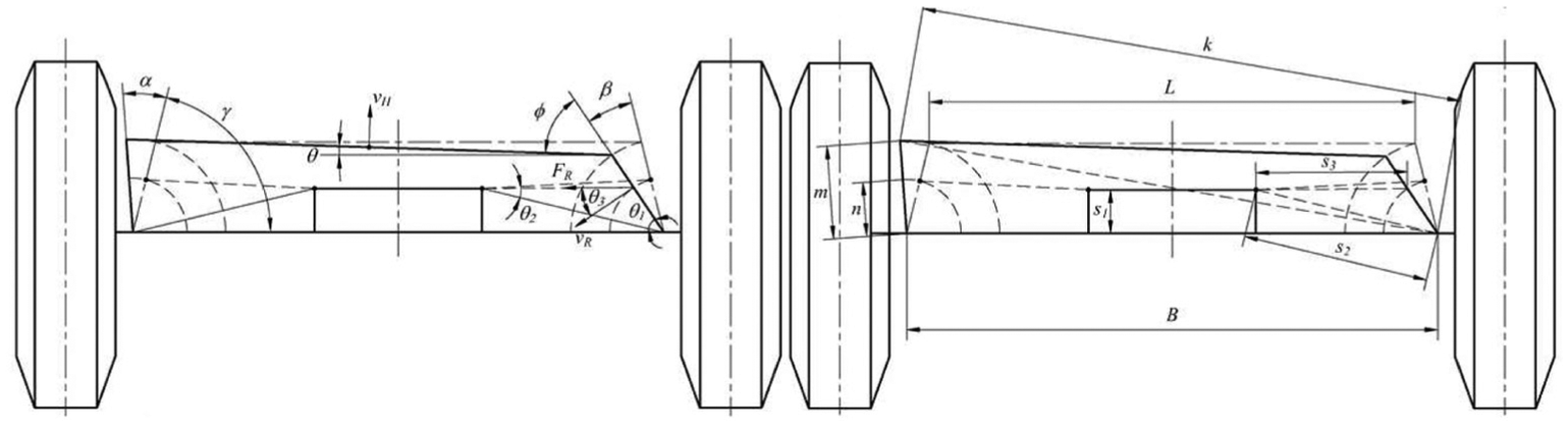
Simplified mechanical structure of EHSSS with single axle.
Kinematics
First, we can define the left steering angle of left tire turning around the kingpin as


Dynamics
According to the steering mechanism shown in Figure 1, the motion of this mechanism can be simplified as three parts. The first motion is the rotary movement of the left assembly including left tire, left hub, left steering knuckle, and left knuckle arm, while the second motion is the rotary movement of the right assembly including right tire, right hub, right steering knuckle, and right arm. The third motion is the movement of the tie rod, which can be decomposed translation and rotation around centroid. The dynamical equation of the system can be established by Lagrangian equation for a vibration system with damp.
The Lagrangian equation is expressed as follows

where
The kinetic energy of the system can be expressed as follows
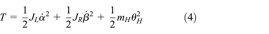
where

where

The potential energy of the system shows the elastic energy of the tires and other mechanisms, and U can be simplified as follows
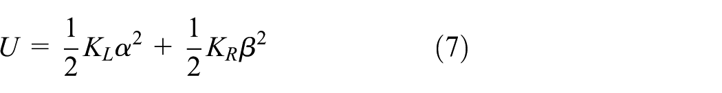
where
The dissipation energy generates from movements of the damper characteristics, such as the steering knuckle rotation around kingpin, the tire steering, and other motions. D can also be simplified as follows

where
According to the principle of virtual work,

In order to simplify calculating, concept of virtual velocity and virtual power is led into, and the expression of
where


Generalized force
Hydraulic model
The hydraulic part of the EHSSS with single axle is simplified in Figure 5. Obviously, electro-hydraulic control system contains a servo solenoid valve and two steering actuation cylinders, and these two cylinders are controlled by one valve. System parameters are shown in Figure 5. In order to get the main characteristics, a proper simplification is made, so we assume that (1) hydraulic oil source is ideal, that is to say,

Simplified hydraulic system of EHSSS with single axle.
First of all, the relationship of the valve port, pressure difference, and fluid flow is as follows


where
Then, we can obtain the following equations according to flow continuity equation


where
Equations (21)–(28) are the mathematical models of hydraulic system, and all the above equations can form the valve control dual-cylinder model. With the analysis of this mathematical model, the main characteristics of EHSSS can be obtained.
Control model
Classic proportional–integral–derivative (PID) controller is widely used in engineering application. This article mainly focuses on whether the electro-hydraulic control steering system can be fulfilled, and we pay close attention to main control performance with a simple controller. It will be valuable for engineers if the PID controller can achieve good tracking performance. Then, the incremental PID control algorithm is used in this article and can be programmed in PLC as follows

Obviously, the above mathematical model of the electro-hydraulic control steering system is extremely complicated. Despite all this, we also find that the system can be abstracted as the model of valve control cylinder. Unlike the traditional one, the mechanical part in this article has nonlinear kinematics and dynamics, and the hydraulic part has series cylinders. It is difficult to obtain the performance analysis through the classic control theory. To figure out the steering performance easily and intuitively, co-simulation based on AMESim and ADAMS is used to deal with it.
Co-simulation model and analysis
It is important to check that the proposed EHSSS system can realize precise steering performance. Before manufacturing an actual prototype, simulation is an effective means to research probable performance and investigate potential options, accelerating design and reducing cost. A co-simulation model for the system was built based on ADAMS and AMESim due to the advantages of ADAMS for mechanism dynamics and AMESim for hydraulic system simulation.
ADAMS model
The steering geometry model was built in Software Pro/E (Figure 1) and imported into ADAMS, as shown in Figure 6. To reduce simulation complexity, we combined several parts without affecting the steering dynamic characteristics. The steering knuckle and wheel hub (see Figure 1) can be combined because these parts are relatively fixed, and similarly, the three parts of the tie rod can also be combined. 22
Steering model with constraints based on ADAMS.
The final ADAMS model consisted of 12 units: vehicle frame, left and right steering knuckle units, tie-road units, left and right actuator rods, left and right actuator cylinders, left and right actuator rod balls, and left and right tie rod balls. Corresponding constraints were added to the ADAMS model, as shown in Figure 6, including two fixed, one translational, four revolving, four cylindrical, and four spherical joints. From the joint constraints, the DOFs were 12 × 6 − (2 × 6 + 1 × 5 + 4 × 5 + 4 × 4 + 4 × 3) = 7, which correspond to vehicle frame translation, steering knuckle units revolving around the kingpin, tie rod revolving along the axle itself, left and right actuator rods revolving in the cylinder, left and right actuator rod balls revolving along the axle itself. Only the former 2 DOFs are useful in actual vehicles, and the most important is the steering knuckle units revolving around the kingpin.
To simulate tire and road interaction forces in dynamic applications, a tire model should be added to the ADAMS model, as shown in Figure 7. Stationary loads are larger than dynamic loadings for heavy vehicles, so we ensure that the tire model can simulate the stationary condition. In ADAMS tire models, the Magic Formula (MF) tire model meets this requirement. The newest MF tire model is PAC2002, which includes more advanced tire-transient modeling using contact mass at the contact point with the road. This provides a more realistic dynamic tire model response for large slip, low speed, and stationary. 1 Thus, the PAC2002_315_80R22.5 model and two-dimensional (2D) flat road were used in the ADAMS model.

Steering model with tire and road surface based on ADAMS.
AMESim model and co-simulation
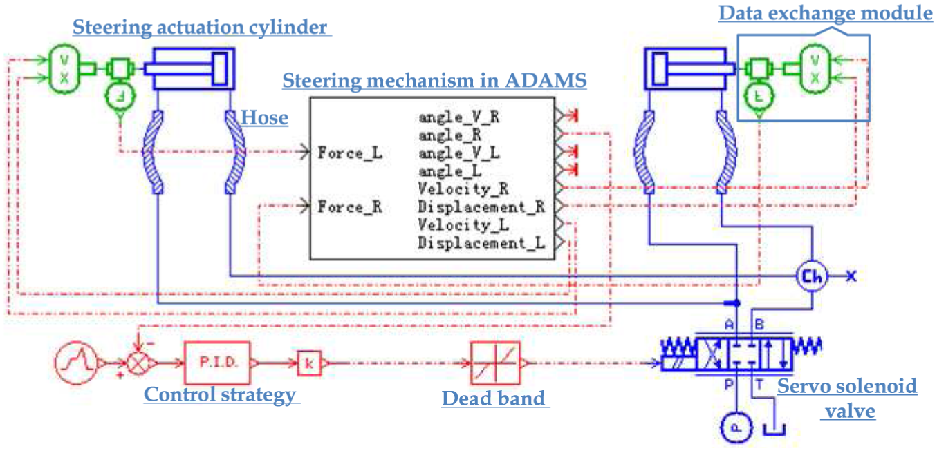
The electro-hydraulic control system is the key part to the vehicle steering system. Therefore, the simulation must incorporate a hydraulic model, including the hydraulic actuator, hose, pump, control valve, controller, and so on. The hydraulic model was developed in AMESim, as shown in Figure 8. To facilitate the analysis, we retained the control valve and actuator, while removing the other components, since this dictates the main control characteristics of the steering system.
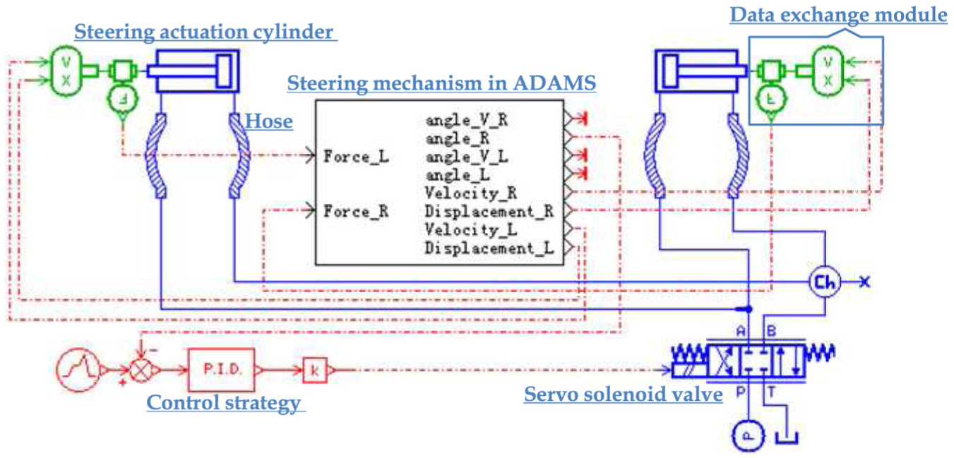
Co-simulation model of electro-hydraulic servo steering system using AMESim and ADAMS.
Since ADAMS and AMESim are separate software modules, an interactive interface should be used in co-simulation. AMESim provides a co-simulation mode to realize this, as shown in Figure 9. AMESim solves state equations relating to the hydraulic model and gathers the results of the multibody model at fixed time from ADAMS. Similarly, ADAMS receives information regarding the hydraulic model from AMESim. Thus, AMESim is the main control software, including the human–computer interaction window. When defining the communication interval in AMESim, data exchange evolves at each time interval. 2
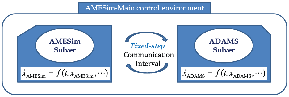
Co-simulation processes between AMESim and ADAMS.
Figure 8 shows that there are four exchanged state variables in the ADAMS model, the displacement and velocity along the rod of each actuator, and there are two exchanged state variables in AMESim model, and the force in each actuator generated by hydraulic power. It is critical that the units and directions of the state variables should be correct.
Simulation analysis
To design the actual steering system, we should investigate the influence of the parameters of key parts on the control characteristics. The key parts of the system include control valves, pipes, and external load. With suitable parameters in the system design, the electro-hydraulic steering control system can track a steering angle command quickly and accurately. A uniform standard signal was chosen as the command for consistently.
Valve parameters
The servo solenoid valve (component 1 in Figure 2) is the most important control element. Its characteristics strongly influence the control performance. In the actual EHSSS, component 1 could be a proportional, servo solenoid, or servo valve. The main differences are their frequency response, dead zones, and hysteresis. For appropriate valve selection, the influence of these three parameters on control performance should be analyzed in simulation.
Frequency response
The proportional valve frequency response is approximately 15 Hz, while servo solenoid valve can reach over 50 Hz, and the servo valve even higher. We set valve frequency in the range 5–50 Hz for the co-simulation model.
Depending on the demand of actual multi-axle vehicles, the extreme ramp command requires the highest steering speed, as shown Figure 10. Figure 11 shows the tracking error between command and actual angles for the co-simulation at the different valve frequency responses. The tracking error is up to 3° at 5 Hz, with significant oscillation. The tracking error decreases as the valve frequency increases, with lessening effect, and plateaus over 30 Hz. Servo solenoid and servo valves can meet this requirement in the terms of frequency response.
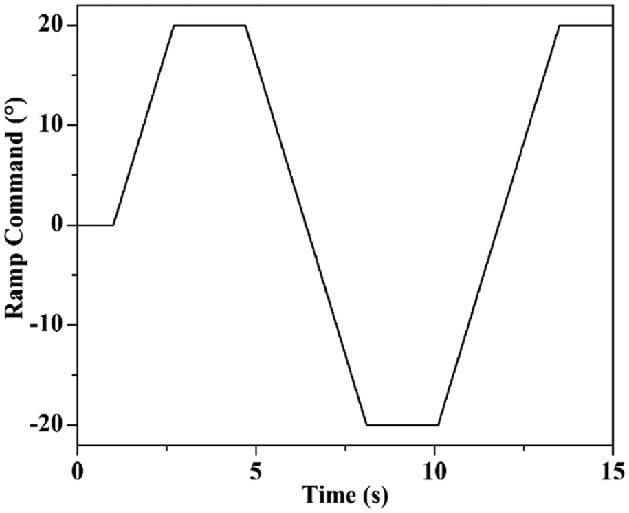
Ramp command.

Tracking error with different valve frequencies.
Dead zone
To analyze the influence of the dead zone on control performance, the simulation model was modified, as shown in Figure 12. The proportional valve dead zone is approximately 20%, while the servo solenoid and servo valves have almost no dead zone. For simulation, the dead zone was set at 0%, 1%, 5%, 10%, and 20%, with results shown in Figure 13. Tracking error increases as the dead zone decreases, and the error approaches 6° when the dead zone is 20%. Thus, control performance is seriously affected by the valve dead zone. Generally, servo solenoid and servo valves can ensure dead zones less than 1%, which meet the requirement for the proposed EHSSS.
Simulation model with dead zone.
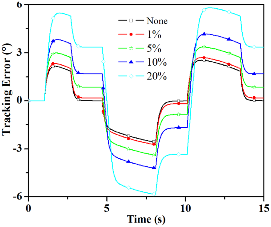
Dead zone effect on tracking.
Hysteresis
Hysteresis also affects control performance, so hysteresis was also added to the simulation model, as shown in Figure 14. Hysteresis of traditional proportional valves is at least 5%, although some proportional valves with spool feedback control can realize good hysteresis, even similar to the typical 0.2% hysteresis of servo solenoid and servo valves. Hysteresis was set to 0%, 0.2%, 1%, and 5% for simulations, as shown in Figure 15. Hysteresis ≤1% has little or no effect on tracking error. However, tracking error increases significantly as hysteresis reaches 5%. Therefore, proportional valves with spool feedback control, servo solenoid valves, and servo valves can meet the hysteresis requirement for the proposed EHSSS.

Simulation model with hysteresis.

Hysteresis effect on tracking.
From the above simulations, servo solenoid and servo valves are the most suitable control elements for the proposed EHSSS. However, the servo solenoid valve has superior anti-pollution and cost performance to the servo valve. Thus, we adopted the servo solenoid valve as the preferred hydraulic control component.
Pipe parameters
In actual EHSSS, the parameters of the pipes between the control valve and actuator, that is, the length and diameter, are also important and should be selected appropriately. These are usually hosepipes, and the length can reach 3 m or more. To analyze pipe parameter effects on control performance, the length and inner diameter were set at several values in the simulation model, as shown in Figures 16 and 17.
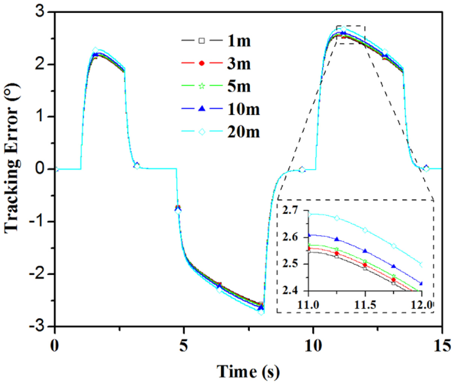
Tracking error for different hydraulic pipe lengths.

Tracking error for different hydraulic pipe inner diameters.
The length of the pipe has a little effect on tracking error when the length is less than 9 m. Therefore, it is acceptable to use longer pipe if required by the installation position.
The inner diameter of the pipe also has a little effect on the tracking error once the diameter exceeds 6 mm. The tracking error can reach 4.15° when the inner diameter is 4 mm. The differential pressure loss sharply increases with small inner diameter, reducing the driving pressure, which reduces the power transfer, and consequently produces larger tracking error. However, the inner diameter should not be too large. Larger inner diameter requires larger hydraulic control volume, which will decrease response speed and degrade pressure buildup speed. Thus, optimal flow capacity and response speed would be achieved with the inner diameter of approximately 10 mm.
Load parameters
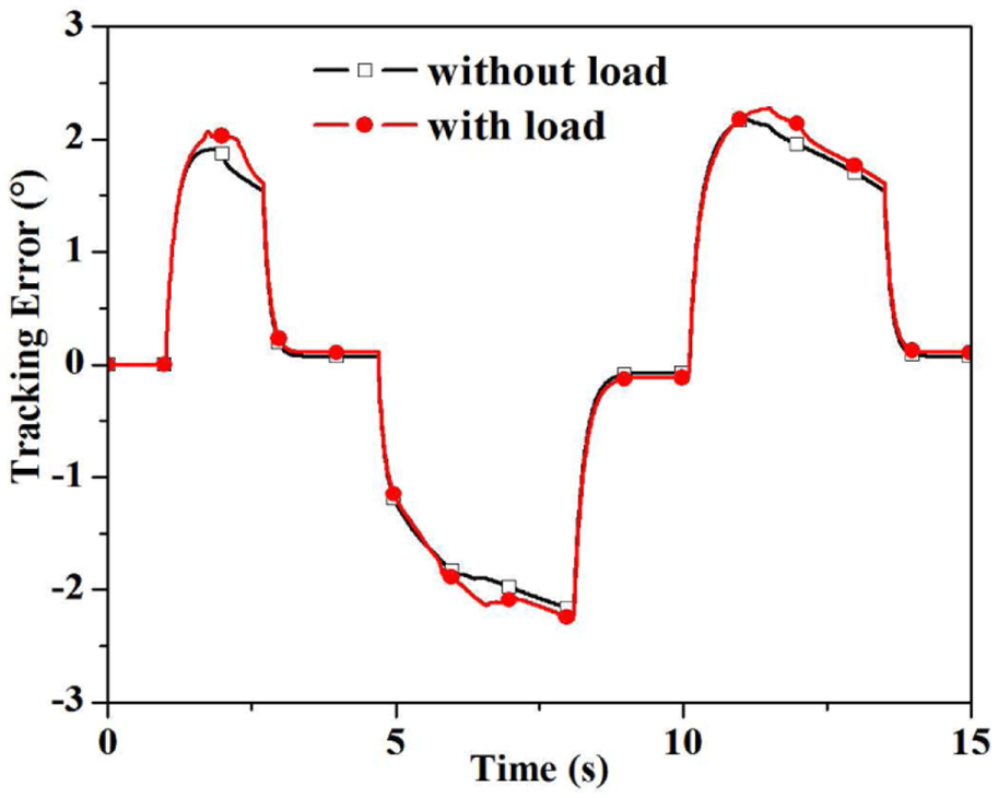
The simulation analyses above were for the multi-axle vehicle in the no-load condition. For an actual multi-axle vehicle, such as the all-terrain crane, single-axle load can reach 6 tons, which should also be simulated. Therefore, a force of 58,800 N was added on the tire to simulate the vehicle load, as shown in Figures 18 and 19, for tracking error and hydraulic pressure, respectively. Tracking error is little affected by the load, with a very small increase in the loaded condition due to increasing leakage. Thus, the EHSSS control performance is not influenced by load.
Tracking error under load.

Hydraulic pressure under load: (a) without load and (b) with load.
Experimental results
Simulation results for the designed multi-axle EHSSS show good dynamic tracking performance. This was verified experimentally in a practical system. The EHSSS was applied to the actual seven-axle all-terrain crane (Figure 1), and the system performance was extensively tested. The actual parameters are shown in Table 1.
Values of electro-hydraulic servo steering system.

This crane includes two parts: the chassis and working equipment on the chassis. The chassis was a general chassis, used for many multi-axle vehicles. For our evaluations, the crane without working equipment was the without load case, while the crane with the working equipment was the full load case.
The hydraulic system for the crane is shown in Figure 20. The steering swing arm mechanism was used for the front three axles, and these axles are driven by two gear pumps with the hydraulic power steering gear. The EHSSS was installed for the rear four axles (axles 4–7 in Figure 20), which are supplied by variable displacement pump. 23

The proposed electro-hydraulic power steering system for the actual all-terrain crane of Figure 1.
The running test without load was implemented on flat road, as shown in Figure 21. To verify the dynamic steering performance for large angles, the vehicle was sharply turned, with the angle of the first axle, as shown in Figure 22. The largest possible angle can approach 40°, and this angle is large enough in actual driving. The running test with full load was also implemented on flat road. The vehicle was also sharply turned, with first axle angles, as shown in Figure 22. The steering angle for this condition was less than the no-load case for safety concerns with the large scale of the working equipment on the chassis. The steering angle still approached 30°. The angle of the seventh axle is the largest for the rear four axles in the driving condition, so we limit our discussion to this axle.

Running test with no load on flat road.
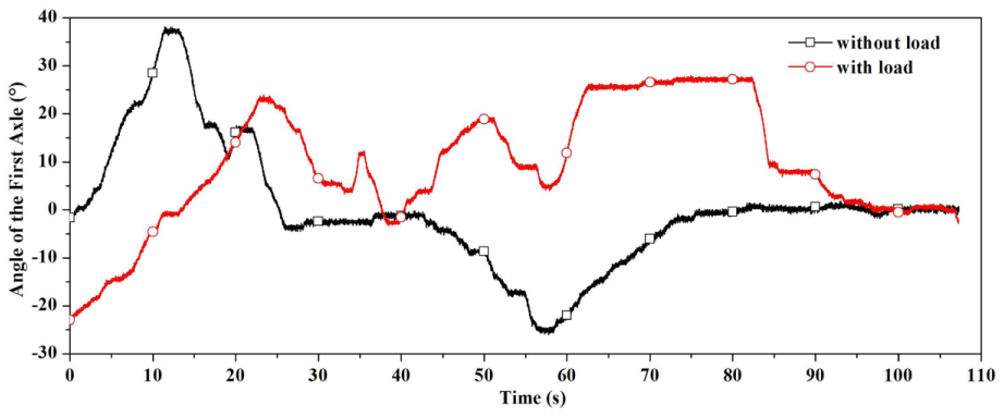
First axle angle for the actual crane driving on flat road without load and with load.
In no-load case, the command and actual angles of the seventh axle are shown in Figure 23 and consequential tracking error in Figure 27. The tracking error can be controlled to less than 2°, which is appropriate to the application. The system and load pressures are shown in Figure 24. The load pressure difference is about 1 MPa, which is in accordance with the simulation results. Thus, the load is minor in the running condition, and the EHSSS performance is very good.
Seventh axle angle for the actual crane driving on flat road without load.

Supply and load pressure of the seventh axle for the actual crane driving on flat road without load.
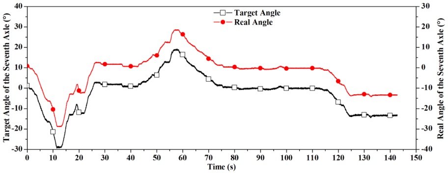
In full load case, Figure 25 shows the command and actual angles of the seventh axle, and tracking error is shown in Figure 27. The tracking error can also be controlled in the load case to less than 2°. To guarantee driving capacity in the full load condition, the system pressure was increased to approximately 20 MPa, as shown in Figure 26. Thus, tracking error is not affected by the load, and the EHSSS performance is also very good in the full load condition.

Target and real angle of the seventh axle for the actual crane driving on flat road with full load.

The tracking error of the seventh axle for the actual crane driving on flat road without load and with full load.

Supply and load pressure of the seventh axle for the actual crane driving on flat road with full load.
Finally, for the multi-axle heavy vehicle, the designed EHSSS with the servo solenoid valve has the optimal dynamic steering performance in actual running test.
Conclusion
This work proposes an EHSSS for use in multi-axle heavy vehicles. The novel EHSSS was designed to include the functions of servo steering, locking, emergency manual operation, and overload protection. It is important to select appropriate component type and parameters for the main function of servo steering. A co-simulation model using AMESim and ADAMS was established to analyze dynamic steering performance with different parameters for the valves, pipes, and loads. To guarantee good steering performance, the control valve should meet the demands of natural valve frequency more than 30 Hz and dead zone and hysteresis less than 1%. Servo solenoid valves were most suitable rather than servo or proportional valves because of their cost-effectiveness and desired dynamic characteristics. Dynamic steering performance of the proposed EHSSS was not significantly affected by pipe and load parameters.
The designed steering system was experimentally verified to provide sufficient driving capacity for multi-axle heavy vehicles, multi-functional control, improved dynamic steering performance, minimal tracking error, and convenient cost-efficiency. The tracking error can be controlled to less than 2°, which is appropriate to the application, and the tracking error is not affected by the load. The designed EHSSS can serve as a reference study when implementing multi-axle vehicle chassis using dynamic steering systems. The proposed system can be applied to the wide field of multi-axle heavy vehicles and other industrial or mobile machinery, such as all-terrain cranes, girder transport vehicles, mining dump trucks, and platform lorries.
Footnotes
Academic Editor: Rahmi Guclu
Declaration of conflicting interests
The author(s) declared no potential conflicts of interest with respect to the research, authorship, and/or publication of this article.
Funding
The author(s) disclosed receipt of the following financial support for the research, authorship, and/or publication of this article: This work was supported by the Opening Fund of State Key Laboratory of Fluid Power and Transmission and Control (grant GZKF-201216) and the Foundation of Fujian Educational Committee (grant JA13051).