
Abstract
Hydraulic retarders are auxiliary braking devices that reduce vehicle speed by converting its kinetic energy into thermal energy of a working fluid. This study analyzes the torque-output characteristics of a new type of hydraulic retarder and optimizes its control strategy under different braking conditions. The design of an observer is based on an analysis of the vehicle dynamic system to ensure that it sets the control target of the dynamic filling ratio for hydraulic control system. With the assistance of the observer, the hydraulic retarder can produce the required braking torque as quickly and as accurately as possible. This study simulates a feedback control system of the vehicle dynamic model with the observer. The results prove that even if the vehicle is driven under complex conditions wherein the slope of the road is changed, the observer effectively sets a control target of the filling ratio for the hydraulic control system. This mechanism strengthens the adaptability and accuracy of the hydraulic retarder control strategy.
Introduction
Hydraulic retarders (HRs) are auxiliary braking devices of vehicles that can reduce vehicle speed by converting the kinetic energy of vehicle to thermal energy of working fluid.1,2 Instead of service braking, HR can be used to regulate vehicle speed effectively under non-emergency braking conditions. Compared with other auxiliary braking devices, HR has the advantages of high braking power, durable efficiency, and zero pollution.3–5
Given the development of heavy vehicles and the demand for safe and economical driving, the control strategy of different braking requirements has become complex and important. 6 The braking torque produced by HR is influenced by three factors, namely, rotational speed of the rotor, radiating power7,8 of coolant circulation, and filling ratio of the working chamber. A vehicle subjected to different braking conditions requires HR to produce different braking torques to satisfy braking requirements. However, in a braking process where HR is involved, a driver fails to regulate the rotational speed of the rotor and the radiating power of coolant circulation; change in braking power is accomplished by controlling the filling ratio of the working chamber.9,10 Therefore, analyzing the control strategy of the braking torque for HR torque-output requires an analysis of the control strategy of the filling ratio of the working chamber.
In Li et al., 11 the control strategy of the filling ratio sets four braking shifts with filling ratios of 25%, 50%, 75%, and 100%, where 25% means that the fluid occupies 25% of the working chamber, and so on. When the braking torque is required, the driver should select certain braking shifts to achieve braking requirements. This study analyzes the relations between the rotational speed of the rotor changing over time and the temperature rise of the changing working fluid over time when continuous braking torque is required in the speed reduction control process. In Sorli et al., 12 a control strategy of constant-speed control is proposed using HR. To satisfy the different braking requirements, the feedback control system is adopted to control the filling ratio, which is used in the current vehicle speed as feedback signal. By identifying the difference between the current vehicle speed and the target constant vehicle speed, the control strategy of the filling ratio of the upshift or downshift is set for the hydraulic control system. The target constant vehicle speed is then achieved.
The aforementioned filling ratio control strategy encounters two problems. First, the hydraulic control system cannot automatically select the best braking shift during the speed reduction control process. This strategy not only increases the operational complexity of the braking system but also renders the braking torque difficult to use. If a high shift is selected, the braking power of HR may exceed the radiating power of coolant circulation, which significantly increases the temperature of the working fluid. Eventually, HR will not work continuously. If a low shift is selected, the braking efficiency of HR may be reduced, which will result in a missing braking torque. Second, no braking shaft can satisfy the constant-speed requirements of the constant-speed control process. In this scenario, the hydraulic control system constantly changes the braking shift to sustain vehicle driving at a target constant speed. The vehicle then takes a long time to reach the state of constant-speed driving. If the disturbance signal of the changed slope is used as input in the feedback control system, the time required by the vehicle to reach the state of constant-speed driving is extended.
Li et al. 13 introduced a refined HR with different control performances of filling ratio. The refined HR can produce a step-less braking torque without setting the shift. The hydraulic control system can control the filling ratio of the working chamber at any value as needed. The feedback control system proposed in this study is almost the same as above, except that the control strategy of increasing and decreasing filling ratio is set when the difference between the target vehicle speed and the current vehicle speed is detected. HR can produce a step-less braking torque. Constant-speed control can be achieved through exact filling ratio without changing shifts constantly. However, the performance of the control strategy proposed in this study is highly influenced by the delay of the feedback control system, which leads to constant changes in the filling ratio before the required filling ratio is achieved. This finding is applicable especially for heavy-duty vehicles, which are mass-dominant systems. Such changes cause the entire braking process and vehicle speed to be underdamped.
In this study, the mounting position of HR is introduced and the torque-output characteristics of the refined HR are analyzed. The entire braking process is then divided into three stages. The different stages have corresponding control strategies of filling ratio. The observer is designed to set the control target of the filling ratio for the hydraulic control system under different braking conditions to efficiently control the filling ratio. MATLAB/Simulink software is used to simulate the feedback control system of the vehicle dynamic model with the controller. The performance of the observer is tested under changing road slope. The vehicle system is then analyzed.
Basic analysis of HR
Mounting positions
The working chamber of the HR consists of a rotor and a stator. The stator can be fixed to the engine or transmission, whereas the rotor is connected to the crankshaft with a gear unit. The rotational speed of the rotor is proportional to the crankshaft. According to different requirements, HR can be mounted on the driving system before or after the transmission as shown in Figure 1. In this study, HR is connected to the engine before transmission.

Mounting positions of HR: (a) mounting position before transmission and (b) mounting position after transmission.
Thermodynamic analysis
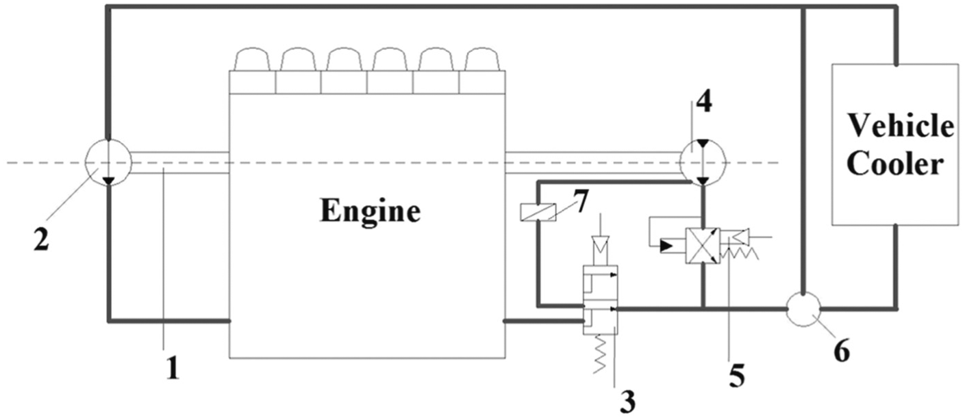
Coolant circulation with HR is shown in Figure 2. The coolant is pumped into the engine from the water pump and radiates the engine. When HR is turned off, the two-position, three-way valve is closed to allow the coolant to flow to the thermostat or to the radiator according to the temperature setting. This circulation is similar to the traditional vehicle coolant circulation. When HR is switched on, the two-position, three-way valve is then opened to allow the coolant to flow directly from the engine to HR. The HR filling ratio is dynamically controlled by the pressure control valve mounted downstream. Subsequently, the coolant flows to the thermostat in a similar manner.
Coolant circulation of vehicle with HR.
Thermodynamic analysis is conducted at the HR entrance. The radiating power (

where Q is the internal energy produced by HR; c is the specific heat;
The mass flow rate can be expressed as

where n is the rotational speed of the engine.
Torque-output characteristics
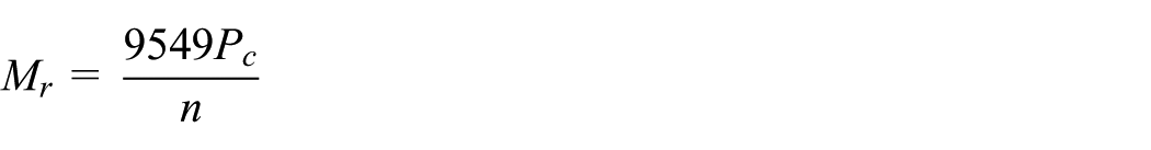
When the vehicle is being driven on the road, the rotor rotates with the crankshaft. When the braking torque is required, the working fluid flows into the working chamber. The braking torque is then produced as a result of the agitation of the fluid by the rotating rotor. The kinetic energy of the vehicle can be converted to thermal energy of the working fluid, and the working fluid with high temperature then flows into the radiator to reject the heat. Therefore, the braking power produced by HR is totally determined by the radiating power of coolant circulation. The braking torque capacity of HR can be expressed as Bergmann et al. 15

where
The radiating power of coolant circulation differs according to the devices used in coolant circulation. In this study, the water pump in the coolant circulation is driven by electricity. Therefore, the radiating power is not influenced by the rotational speed of the crankshaft and is then held constant.
The torque-output characteristics of HR are shown in Figure 3. Curve AB describes the maximum braking torque with a filling ratio of 100%, curve DC depicts the minimum braking torque with a filling ratio of 30%, and curve BC shows the radiating power of coolant circulation. When rotational speed is within

Torque-output characteristics of HR.
Observer analysis of filling ratio
The braking process is divided into three stages. The filling ratio should be dynamically controlled at all stages with different control strategies to automatically complete the braking requirements. The mass identification model is analyzed to satisfy the fast response of the observer in braking conditions.
Braking process
A vehicle driving downhill has two braking requirements, namely, reducing-speed control and constant-speed control. 13 According to the torque-output characteristics analyzed, the braking process is divided into three stages as shown in Figure 4. Stages 1 and 2 are associated with reducing-speed control, whereas Stage 3 is associated with constant-speed control.
Stage 1

Stage 2

Stage 3. The braking torque produced by HR at this stage is determined by the equation of driving force and resistance, which is discussed in detail in the next section.

Rotational speed of rotor changing over time in process of speed reduction and constant speed control.
Observer design
The observer is designed for each stage to calculate the filling ratio and to satisfy specific braking requirements.
Stage 1. The filling ratio and braking torque of HR from equations (2) and (3) are

Stage 2. To allow HR to work efficiently according to torque-output characteristics, maximum braking power is determined by the braking capacity of HR. The maximum braking torque that could be produced by HR at this stage is


Stage 3. The filling ratio and braking torque of HR are analyzed under two different conditions.
Condition A
Constant-speed control strategy is started at any time while HR works at Stage 1 or 2. Under this condition, the current vehicle speed is the target constant speed
Establishing the two equations before and after HR leads to Stage 3, which involves the equation of reducing-speed control under a partial filling ratio at Stage 1 or under a full filling ratio at Stage 2. The equation of constant-speed control under a target partial filling ratio at Stage 3 is


where k is the sampling time point;
Time interval is assumed to be short during the time moments. Therefore, the following slope and braking forces in equations (5)–(8) are considered unchanged


With the assumptions in equations (5)–(8), the target filling ratio is

Condition B
HR is already working as the control strategy of Stage 3, but the slope of the road changes.
The slope changes to


With the assumptions in equations (6) and (7), the target filling ratio is

Conditions A and B can be expressed by the same equation. Any detected acceleration change causes the controller to set a new control target of the filling ratio.
In conclusion, the filling ratio controller at different stages are
Stage 1.
Stage 2.
Stage 3.
Mass identification model
In this section, a mass identification model is introduced to calculate the mass of the vehicle needed at Stage 3 of the observer.
Based on Figure 5, 16 the following equation of the driving force and resistance is established as follows


where
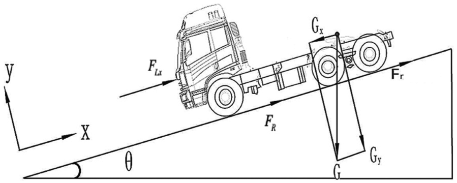
Vehicle driving force and resistance.
The equations of the moment at the beginning of the braking conditions when HR is involved are as follows


Time interval is assumed to be short, and the slope is considered unchanged during time moments. Together with equation (5), the mass identification equation is

Simulation analysis
The vehicle dynamic system model with the observer is established based on equation (9). The reducing-speed and constant-speed control strategies are simulated. The performance of the observer can be analyzed using the simulation results.
Simulation model
The feedback control system of the dynamic vehicle model with the observer is built according to the specific format of the equations at different braking stages as shown in Figure 6. The model consists of three main sub-models, namely, the filling ratio observer, HR, and the vehicle. When the vehicle is being driven on the road, the dynamic difference between the target constant vehicle speed and the current vehicle speed and acceleration are constantly sent to the observer. When braking force is required, the observer automatically calculates the control target of the filling ratio under the current braking condition. The hydraulic control system regulates the filling ratio of the working chamber according to the filling ratio control target set by the observer.

Feedback control system of vehicle dynamic model with observer.
The simulation conditions are as follows: the vehicle is being driven on a ramp at an initial speed, and the reducing-speed braking control is activated. The constant-speed braking control is activated later at a certain vehicle speed. The parameters of the vehicle dynamic system are listed in Table 1.
Parameters of dynamic vehicle system.

Analysis of simulation results
Figure 7 shows the simulation results of the braking process. Figure 7(a) shows that the vehicle is being driven downhill at initial speed
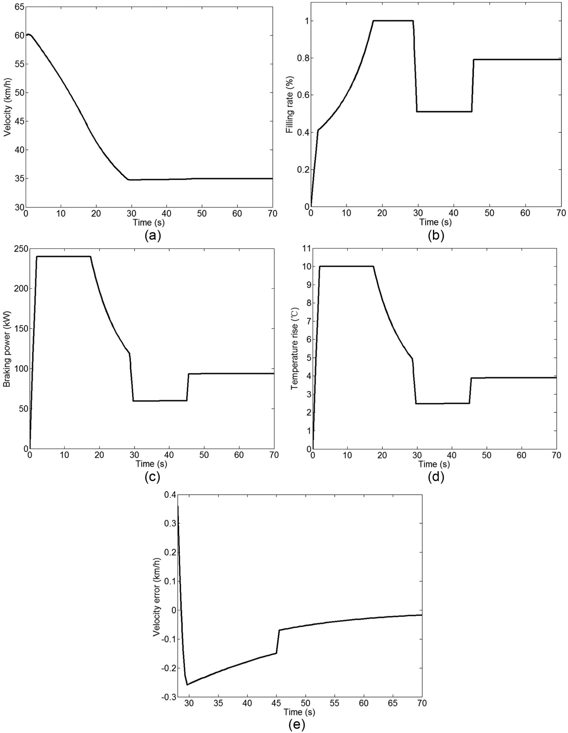
Simulation results: (a) vehicle speed changing over time, (b) filling ratio changing over time, (c) braking power of HR changing over time, (d) temperature rise of working fluid changing over time, and (e) vehicle velocity changing over time.
Conclusion
A filling ratio observer is designed in this study for the feedback control system and to set the filling ratio control target of the hydraulic control system under certain braking conditions. With the assistance of the observer, HR could produce the required braking torque as quickly and as accurately as possible to satisfy complex requirements. MATLAB/Simulink software is used to simulate the vehicle equipped with a controller. Based on the simulation results, the following conclusions are made:
The braking power of HR is highly influenced by the radiating power of the coolant circulation in Stage 1. The radiating power in this study is held constant at any driving condition. The radiating power can be related to the rotational speed of the engine if the water pump is driven by the crankshaft and the mass flow rate should be considered. The curve of the radiating power in the torque-output characteristics could differ. However, the observer in this study is also capable of setting the control target of the filling ratio for the hydraulic control system.
In the speed reduction control process, the observer can automatically detect the optimal braking torque of HR and calculate the required filling ratio of the hydraulic control system. Safe driving is ensured because the filling ratio is not changed drastically.
In constant-speed control, the observer could set the filling ratio control target for the hydraulic control system as fast as possible even if the slope of the road is changed. Acceleration could be used together with mass identification model to satisfy the requirements.
The dynamic vehicle model with HR proposed in this study can be used in analyzing braking systems, especially for heavy-duty vehicles that use engine brake, service brake, and HR in braking conditions.
Footnotes
Academic Editor: Rahmi Guclu
Declaration of conflicting interests
The author(s) declared no potential conflicts of interest with respect to the research, authorship, and/or publication of this article.
Funding
The author(s) disclosed receipt of the following financial support for the research, authorship, and/or publication of this article: This study is supported by the Program for New Century Excellent Talents in University (NCET-08-0248).