
Abstract
In this article, a practical iterative algorithm for tuning the parameters of notch filter is presented to suppress high-frequency resonance in ultra-precision motion control. Notch filter is a useful tool to suppress middle- and high-frequency resonance to improve control precision. The traditional tuning method for it depends on the Fourier transform of the positioning error or the modal analysis of the motion stage, which cannot get the optimal control performance. The proposed algorithm can be used to tune the parameters of notch filter iteratively through minimizing a cost function of the positioning error, and it needs only measurement signals in actual motion system rather than detailed model of the motion stage. The proposed algorithm can suppress mechanical resonance and meanwhile minimize positioning error, which are demonstrated by experimental results in wafer stage of photolithography.
Introduction
In ultra-precision motion control system such as hard disk and stage of wafer fabrication equipment, there exist some middle- or high-frequency vibration components due to the excitation of mechanical structure,1,2 which can reduce control accuracy, even destroy stabilization of the control system. As a general control strategy, proportional–integral–derivative (PID) with second low-pass filter can realize fast response and achieve little steady-state error. However, they are incapable for high-energy structure excitation. Digital notch filters falling into infinite impulse response (IIR) and finite impulse response (FIR) can be used to suppress resonance components.
FIR notch filter has the advantages of optimal equiripple and linear phase,3,4 and so on. However, it needs higher order than IIR to realize equivalent performance, which may cause large time lag and occupy more computational resources. Therefore, low-order IIR notch filter has been recognized as an effective tool to suppress middle- or high-frequency resonance in electromechanical system which requires high real time. For example, Semba et al. 5 presented a patent which taught to select a notch filter to suppress resonance in a hard disk drive. Kamalzadeh and Erkorkmaz 6 designed an appropriate notch filter to avoid the first and second modes of structure excitation in ball screw drives. Xu et al. 7 proposed a novel strategy to detect middle-frequency resonance for the speed control of industrial servo systems. And they adopted an adaptive notch filter whose parameters can be adjusted based on fast Fourier transform (FFT) of speed feedback signals to reduce the mechanical resonance. Oh and Bang 8 presented an adaptive notch filter to estimate multiple bending mode frequencies of the deployable manipulator and to minimize the effect of bending vibration. Considering the effect of manufacturing tolerance and variation with temperature on resonance frequency, Kang and Kim 9 presented an adaptive digital notch filter that can identify the resonance frequency of the actuator in hard disk quickly and adjust its center frequency automatically.
The above-mentioned notch filters are tuned depending on engineers’ experience, the FFT of feedback signals, or the modal analysis of the mechanical structure. Although those works have made progress in resonance suppression, a notch filter with optimal control performance cannot be obtained due to the non-rigorous tuning algorithm. The previous tuning methods for notch filter just focused on how to match the filter frequency with the resonance frequency but neglected the selection of filter damping. So those methods cannot improve control precision further, especially for ultra-precision motion control or nano-positioning system.
Iterative tuning is a data-based method to adjust controller parameters through minimizing a certain cost function, and it has been applied in many industrial fields due to the advantage of avoiding the need of detailed model of motion system. Hialmarsson et al. 10 developed the iterative feedback tuning (IFT) theory to adjust the PID controller applied in chemical industry. Then, IFT was adopted in electromechanical system to get the optimal controller parameters. Hamamotoa et al. 11 presented a two-degree-of-freedom (DOF) controller tuning for two-mass–spring systems with friction based on the IFT. Karimi et al. 12 tuned the controller of a magnetic suspension system iteratively for the purpose of making the output error between the designed and achieved closed-loop systems uncorrelated with the reference signal. Feedforward controller can also be adjusted using iterative tuning method; for example, Stearns et al. 13 iteratively tuned the feedforward controller of a wafer stage of a photolithography machine without prior plant model. Considering a fixed structure feedforward controller, Van der Meulen et al. 14 developed an iterative tuning algorithm and achieved controller parameters with respect to the actual plant. The coefficients of multi-input multi-output (MIMO) feedforward controller in wafer scanners were obtained from a gradient approximation–based algorithm using iterative tuning in Heertjes et al. 15 Teng et al. 16 developed an iterative tuning algorithm to realize decoupling thoroughly among 3-DOF in wafer stage. Heertjes et al. 17 used a data-driven self-tuning approach to find the coefficients of the synchronization controller based on FIR filters. Niedzwiecki and Kaczmarek 18 combined the parametric (model-based) and nonparametric (discrete Fourier transform–based) approach to identify the quasi-periodically varying FIR systems such as notch filter. Soon afterward, they 19 provided an online iterative tuning method of generalized adaptive notch filter with the combination of sequential optimization and parallel estimation. And the method can be used to extract the instantaneous frequency of nonstationarity system.
The above works show that the iterative tuning algorithm can tune varied controller parameters and obtain high control performance. However, its application in notch filter tuning to suppress resonance in ultra-precision motion control cannot be found. Niedzwiecki and Kaczmarek tuned the adaptive notch filter by minimizing the tracking error between system output and the estimate one. However, they just focused on the varied frequency estimation without considering the concrete motion control system. The motivation of this article is to present an iterative tuning algorithm to adjust the notch filter parameters adaptively in ultra-precision motion control, which can suppress mechanical resonance appropriately and obtain an optimal control precision.
The organization of this article is as follows. In section “Motion control system,” the motion control system for electromechanical equipment sustained by air bearing or magnetic bearing is introduced. The principle of notch filter in motion control and the corresponding discretization are presented in section “Notch filter in motion controller.” Then, the objective of iterative tuning for notch filter is given, and the solution procedure is deduced in detail in section “Iterative tuning of notch filter.” Next, the effectiveness of the tuning method for notch filter is demonstrated by a wafer stage in practice in section “Application to an ultra-precision stage.” Finally, conclusions are drawn in section “Conclusion.”
Motion control system
An ultra-precision motion stage of electromechanical equipment is usually sustained by air bearing or magnetic bearing. The motion friction can be neglected, and the dynamic model can be described as follows14,15
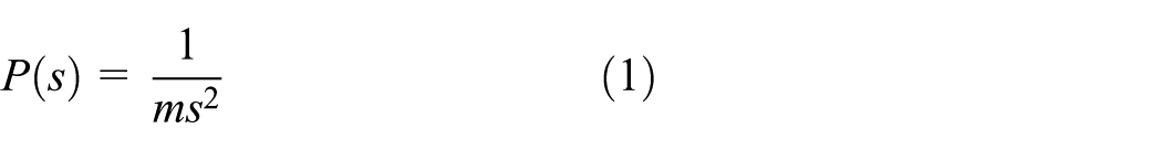
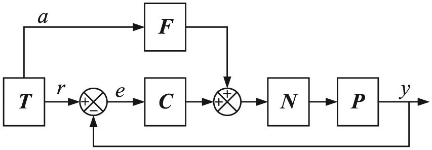
where m is the mass of moving part, s is the Laplace factor. The above model is double integrators theoretically, and the fact one can be substituted through the identification using actual measurement signals in the following iterative tuning for notch filter. The corresponding motion control system is shown in Figure 1, which consists of trajectory planning (T), feedback controller (C), feedforward controller (F), notch filter (N), and plant (P). Nominal acceleration, velocity, and position are planned referring to Lambrechts et al. 20 in trajectory planning. Due to neglecting the motion friction, the acceleration a and position r are just necessary. As a general feedback controller, PID with second low-pass filter can adjust the positioning error and improve stability of the control system, which can be described as follows
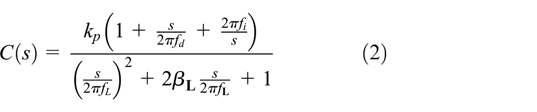
where kp, fi, and fd denote the proportional gain, integral frequency, and differential frequency, respectively, and f
Motion control system of electromechanical equipment.
In Figure 1, subtracting the measurement position denoted by y from the nominal position r, we can get the positioning error denoted by e. Because of the inherent lag in electromechanical system, a feedforward controller is used to improve the response speed, which can be described as follows

where mF is the feedforward controller coefficient, ts is the servo period, and tf is the inherent lag of electromechanical system.
Notch filter in motion controller
Notch filter
Some middle- and high-frequency resonance of mechanical structure can be excited in motion control system, and there is convex component in the Bode diagram of mechanical transfer function. As shown in Figure 2, notch filter can generate concave at certain frequency; thus, it is capable of counteracting the convex component and suppressing the middle- and high-frequency resonance.

Bode diagram of notch filter.
The transfer function of notch filter in Figure 1 can be shown as follows

where fp, βp, fz, and βz denote the pole frequency, pole damping, zero frequency, and zero damping of notch filter, respectively.
The majority of traditional adaptive notch filters are tuned according to fp = fz, βp > βz. As shown in Figure 2, when fp = fz = 260 Hz, the magnitude of traditional notch filter is axis symmetrical about center frequency (260 Hz). However, the vibration energy distribution of mechanical resonance is usually asymmetrical, and the suppression degree of magnitude and two-side center frequency should not be equal, shown as the particular line where fp = 270 Hz and fz = 250 Hz in Figure 2. When the parameters of notch filter are set according to traditional mode, the mechanical resonance can be suppressed. However, the control precision cannot be improved further, especially in nano-positioning motion system such as wafer stage of photolithography.
The aim of this article is to tune the parameters of notch filter iteratively based on measurement data in practice and obtain an optimal notch filter with the same form as the particular mode shown in Figure 2. The optimal notch filter can play a compromise between the responsive bandwidth and the control stabilization. In other words, the bandwidth will be reduced, and the magnitude margin and the phase margin will be increased; thus, the positioning error will be as small as possible.
Discretization
In practice, digital control system is widely adopted with the rapid development of processor technology. The classic method transforming the notch filter from s domain to z domain is bilinear transformation, 21 which can be shown as follows

Substituting equation (5) into equation (4), the transfer function of notch filter in z domain is derived as follows

with


Prewarping
Frequency aliasing can be avoided using bilinear transformation in discretization from s to z domain, but warping in critical frequency will arise due to frequency compression. To overcome this, prewarping 22 can be adopted as follows

where f1 denotes the designed pole frequency or zero frequency of notch filter, and f2 denotes the prewarped frequency that can be the frequency fp or fz in the coefficients of equation (6).
Iterative tuning of notch filter
Objective of iterative tuning
In motion control system, positioning error is an important index reflecting control performance. Notch filter can not only suppress mechanical resonance but also reduce the positioning error. Based on these advantages, we present an iterative tuning algorithm data-based for notch filter to obtain the optimal filter parameters through the minimization of a cost function. The optimization problem is defined as follows

The cost function J(ρN) consisting of the positioning error and parameters of notch filter in iterative tuning can be described as follows

where e(ρN, i) represents the positioning error in motion control system, i denotes the sample instant, M denotes the number of samples in a tuning process, and T denotes the transposition of e. ρN is the coefficient of the discrete transfer function of notch filter in equation (6), which can be resumptively written as follows

As shown in Figure 3, we gather the positioning error denoted by e, notch filter output denoted by n, and measurement position denoted by y to construct the iterative tuning algorithm. The iterative tuning process for notch filter is represented by IT in Figure 3. Through minimizing the cost function in equation (9), the mechanical resonance in motion control system can be eliminated; meanwhile, the optimal parameters of notch filter in equation (10) can be obtained, as well as the parameters fp, βp, fz, and βz in equation (4).

Iterative tuning process for notch filter.
Solution
For ultra-precision motion control system, there are no constraints presenting on the optimization problem in equation (8). To guarantee the convergence, the quasi-Newton method 23 is adopted. The parameters of notch filter in equation (10) can be updated as follows
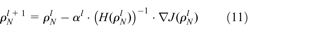
where l is the iterative tuning number, αl is the step length,


where
Mechanical resonance may emerge in steady state of control system, so the iterative tuning algorithm is implemented, as shown in Figure 3. Neglecting the dynamic state, the transfer function between the positioning error and the nominal position is given as follows

Then, the partial derivative of e with respect to

In the above equation, the PID controller C(z) and plant P(z) are irrelevant to the parameters of notch filter, so just the partial derivative of
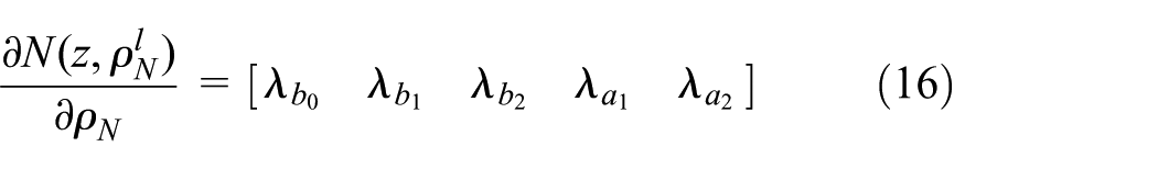
with

As shown in Figure 3, we can observe that

Then, the substitution of equation (17) into equation (15) leads to the following expression

For the unknown model P(z) in equation (18), signals n and y are sampled to substitute them with the following equation

Then, equation (18) can be rephrased as follows
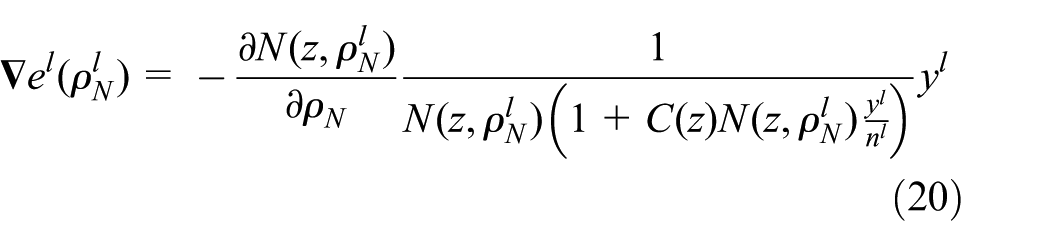
Besides the fixed structure of the feedback controller C(z) and notch filter N(z), equation (20) is an approach depending on the measurement signals. Substituting equation (20) into equations (12) and (13), the parameters of notch filter can be updated according to equation (11).
Convergence of the algorithm
Considering the Hessian matrix of the cost function cannot be positive definite, then the Hessian in equation (13) is substituted by
As we know, the difference of the cost function contains the information of the first-order derivative, which can be shown as follows
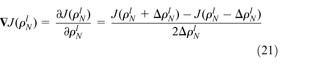
Likewise, considering the difference of the gradient of the cost function, the

where
When either of the following conditions is satisfied
The search direction is set as follows

Otherwise, the search direction is set as follows
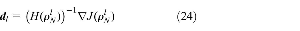
Then, the tuning formula can be updated as follows

The above iterative tuning algorithm lies somewhere intermediate to steepest descent and Newton’s method. And it can overcome the disadvantages such as the negative definite of the Hessian matrix and computational complexity.
The step length αl is an important factor to guarantee the convergence of the iterative algorithm. So, we define a temporary function which is shown as follows

For any number δ which satisfies the condition 0 < δ < 0.5, if
Therefore, the iterative tuning algorithm for the parameters of notch filter is convergent, and also the convergence is demonstrated by practical test in section “Application to an ultra-precision stage.”
Application to an ultra-precision stage
The iterative tuning algorithm for notch filter is tested in ultra-precision motion stage which loads wafer in step-and-scan projection photolithography, as shown in Figure 4. The stage consists of two parts: fine-motion stage moves nanometer level using laser interferometer as measurement system, and rough-motion stage follows at micrometer level using hall sensor. The 3-DOF fine-motion stage is driven by three planar motors with maximum thrust 300 N, and the rough-motion stage is driven by coreless linear motor with maximum thrust 450 N. The servo period of the control system is 400 us, which is also the sample period in tuning process.
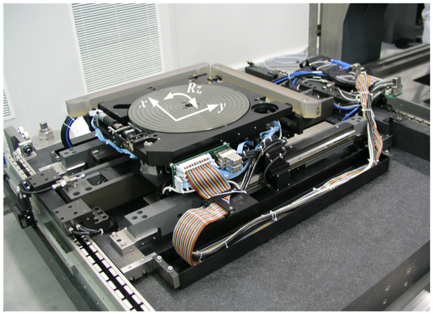
Ultra-precision motion stage.
First, the fine-motion stage is controlled according to the control structure of Figure 3 with the second row of Table 1 as initial values of notch filter. In other words, the notch filter is not used at the beginning. We focus on the improvement of steady-state performance caused by iterative tuning of notch filter, so the dynamic state performance is not considered, and the feedforward controller is neglected. In Figure 3, the control errors e, notch filter output n, and measurement position y are collected to implement the iterative tuning algorithm. The mechanical transfer function and open-loop transfer function are defined in equations (27) and (28), respectively

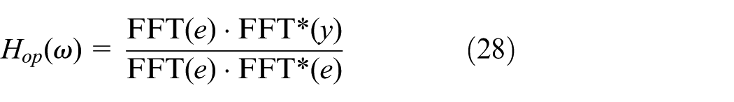
where the * represents the conjugation operator, and FFT denotes fast Fourier transform.
Parameters of notch filter during iterative tuning.

The Bode diagram of mechanical transfer function in y-direction is drawn in Figure 5, which shows a mechanical resonance hump at about 749 Hz obviously. Without the application of the notch filter, the resonance hump leads to a large positioning error within ±1e−5 m, as shown in Figure 6(a), and the power spectrum density (PSD) of the positioning error in Figure 7(a) coincides with the resonance frequency in Figure 5 nicely.
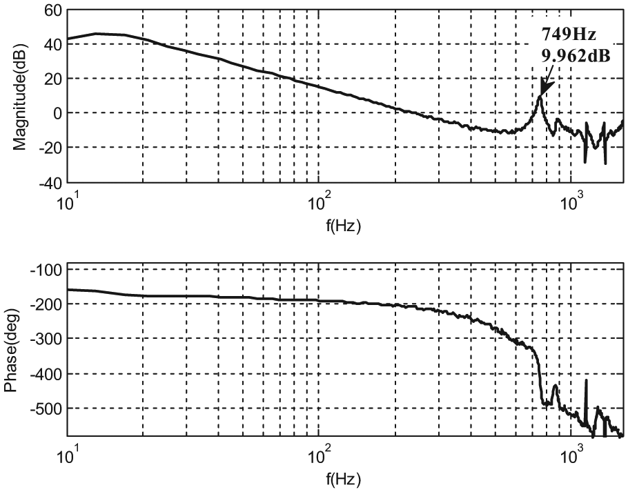
Bode diagram of the mechanical transfer function.
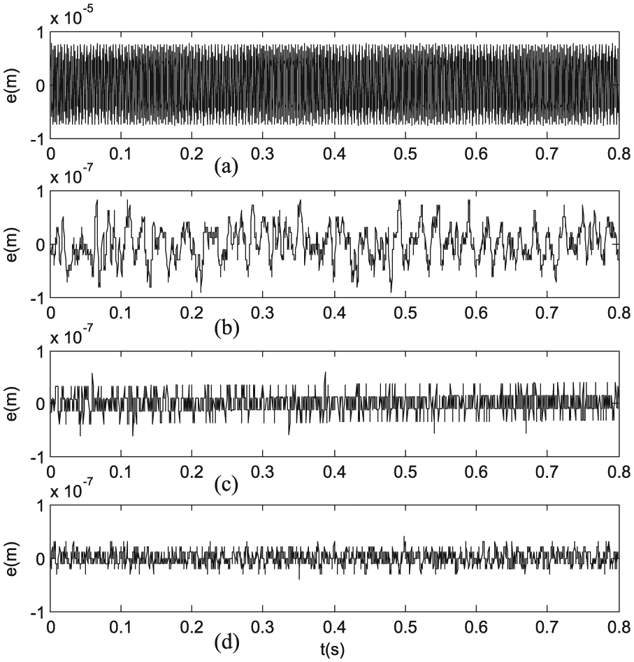
Positioning error during iterative tuning: (a) without notch filter, (b) after the first tuning, (c) after the second tuning, and (d) after the third tuning.

Power spectrum density of positioning error: (a) without notch filter, (b) after the first tuning, (c) after the second tuning, and (d) after the third tuning.
Then, iterative tuning procedure for notch filter is implemented according to section “Iterative tuning of notch filter,” it ends after three times, and the corresponding parameters of notch filer are listed in Table 1. From Figure 6(a) to (d), we can find the positioning error decreasing gradually with the iterative tuning of the notch filter. The positioning error in Figure 6(b) with the first tuning of notch filter is much smaller than the one in Figure 6(a), which shows the positive effect of notch filter. The same result is demonstrated by comparing Figure 7(b) with Figure 7(a) because the resonance frequency disappears with the application of notch filter after one iterative tuning in Figure 7(b).
The notch filter after the first tuning used in control system is similar to the traditional adaptive notch filter based on FFT of feedback signals or the modal analysis of the mechanical structure in previous studies.8,9 However, at this moment, the control performance is not optimal. The objective of minimizing the cost function of positioning error leads to the notch filter updating, and the positioning error decreasing sequentially until a threshold is satisfied. Comparing Figure 6(c) with Figure 6(b), the positioning error is reduced obviously after the second tuning of notch filter, which shows better advantage than the traditional notch filter. Furthermore, the positioning error decreases in Figure 6(d) after the third tuning. The PSD of the positioning error from Figure 7(b) to (d) demonstrates the same results.
Figure 8 shows the open-loop transfer function of the control system after three iterative tunings of notch filter. Comparing the Bode diagram after the first tuning with the one after the second tuning, the control bandwidth decreases from 187 to 109 Hz, the magnitude margin increases from 5.3 to 7.3 dB, and the phase margin increases from 32° to 35°. Although the control bandwidth decreases, the stabilization of the motion system is enhanced, and the positioning error decreases from Figure 6(b) to (c) correspondingly. The open-loop transfer function after the second tuning is almost the same as the one after the third tuning with a subtle difference, which shows that the second tuning of notch filter has already approximated the optimal objective.
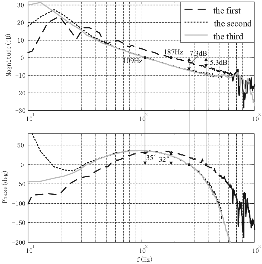
Bode diagram of open-loop transfer function.
The iterative tuning algorithm for notch filter is offline to guarantee high calculation speed in ultra-precision motion control system. The tuning process can be implemented after the stage is reassembled or once in a month to overcome possible changes of working condition such as temperature drift and device degradation.
Conclusion
An iterative tuning algorithm for the parameters of notch filter in ultra-precision motion control is presented in this article. Notch filter can be used to suppress mechanical resonance in motion control system, and the traditional tuning for it is based on the FFT of positioning error adaptively and cannot obtain an optimal control performance. Iterative tuning notch filter is implemented through minimizing a cost function of the positioning error. In order to minimize the cost function, a quasi-Newton’s iterative algorithm is adopted based on actual measurement signals. And an optimal notch filter can be realized which can eliminate mechanical resonance and obtain higher positioning precision in ultra-precision motion control system. The proposed algorithm for tuning notch filter iteratively is demonstrated by experimental results in wafer stage of step-and-scan photolithography.
Footnotes
Academic Editor: Neal Y Lii
Declaration of conflicting interests
The author(s) declared no potential conflicts of interest with respect to the research, authorship, and/or publication of this article.
Funding
The author(s) disclosed receipt of the following financial support for the research, authorship, and/or publication of this article: The research presented in this paper was supported by National Natural Science Foundation of China (nos 51305135 and 51305404), Beijing Higher Education Young Elite Teacher Project (no. YETP0701), and the Fundamental Research Funds for the Central Universities (no. 2015ZD15).