
Abstract
Air-liquid pressurization convertor has been applied in energy boosting which is widely used in sustainable energy automobile. In this article, output dynamic control method is analyzed by model simulation and experimental validation to set foundation for optimization, in which the pneumatic and hydraulic nonlinear combination equations, total nonlinear frictions on pistons, and load nonlinear equilibrium equation are considered. Moreover, influences on output dynamic control characteristics of the late automobile model with nonlinearity are studied. The conclusion can be made as follows: first, the built model is effectively verified by comparison of experimental and simulation results. Second, as one of the key power system parameters, longer piston stroke will lead to better output dynamic property within a certain limit. Third, area ratio is considered to be approximately 8, which can avoid the unsteadiness of the output dynamic characteristics. Furthermore, suitably bigger orifice will greatly promote the characteristic property of the air-liquid pressurization convertor. Finally, under the condition of this article, input pressure can be set to 0.65 MPa to obtain a better power system combination property. This study can provide reference for the optimization of dynamic characteristics of the sustainable energy automobile.
Keywords
Introduction
In recent years, sustainable energy vehicle has gained widespread use as a new kind of green transport. Because of good advantage of simple construction, recyclability, easy maintenance, long lifespan, high energy storage density, and low power consumption,1–6 new kind of power system with energy storage technology of compressed air has come into more and more engineers’ and scientists’ notice. To overcome the problems such as the air leakage, the restricted volume, the incomplete expansion, and the friction of the air which limit the energy efficiency of air-powered engine,7–10 air-powered motorcycle of a new type with a blade-typed motor was invented which can keep the efficiency being over 20% in 2009. 11 Furthermore, in 2012, new air-motor of piston type was proposed, and the performance was examined which shows that the highest engine efficiency can almost be up to 13%. 12
Most of the recent studies are mainly focused on the optimization and optimal structure design for the performance of the power system. An expansion-type pump has been designed by Takeuchi12–34 which can use expansion energy during the working process. A property experiment of air pump driven by inputting gas has been made by Wang10–33, by reciprocating motion of the piston to boost pressure. However, very little study on any of the energy sustainable automobile with air-liquid pressurization convertor is yet published.13–16 In addition, there are still short of researches on dynamic analysis about the energy sustainable automobile, which brings many difficulties on air-powered vehicle’s performance optimization.17–20
As the power system of sustainable energy vehicle contains converter of air and hydraulic, the model of the system and the characteristics of frictions with load present nonlinearity relationship. Regarding the nonlinear friction compensation, Yao and colleagues21–24 and Chen et al. 25 have proposed a servo valve control method with LuGre model–based friction compensation, which considered the adaptive and nonlinear robust control method. Sun et al.26,27 considered the total friction forces produced by the nonlinear stiffening spring, the piece-wise linear damper, and the tire obey in a new kind of nonlinear active suspension model. All28–31 the main methods of dynamic system are modeled rigorously and comprehensive; however, they can be simplified in the sustainable energy automobile system during the motivation of the actuators.
Late model sustainable energy automobile has been proposed in this article including a power boosting device and the actuator unit. In order to improve the dynamic performance of the air-powered vehicle, to begin with, new kind of mathematical model of the sustainable energy automobile with nonlinearity was set up. Next, an experimental station was built to demonstrate the dynamic model. In addition, dynamic characteristics, including the output torque and rotational speed of the sustainable energy automobile, were illustrated through simulation research. What is more, studies on effects of key parameters on the dynamic characteristics are proposed by analyzing the flatness and average values of the output characteristics.
Configuration of the late model sustainable energy automobile
As shown in Figure 1, configuration model of the sustainable energy automobile with air-liquid pressurization convertor is proposed. It mainly includes the input air source in which the input pressure can be controlled by the pressure regulator; a solenoid valve which can choose the input air chamber; one air cylinder which includes one pneumatic piston, which is directly driven by the input air; and two symmetrical liquid cylinders which include two hydraulic pistons in each of the liquid chambers. On the output way of the hydraulic pistons, there are two check valves which can lead the hydraulic fluid to the orientated direction and a hydraulic motor which drives a notional mechanical load simplified as inertia and damping load. Overflow valve will avoid the danger of high pressure in the hydraulic system of the automobile.

Configuration model of the sustainable energy automobile.
In this model of the designed sustainable energy automobile, the hydraulic motor as well as the driving road and gears is considered to be the actuator part, and the air-liquid pressurization convertor is the power boosting part. When the source of air comes into one side of the air cylinder, the three pistons connected together will move toward the other side. At the same time, the compressed hydraulic oil will be forced out of the two liquid cylinders in the same side chambers, and the liquid will be inhaled in the other side chambers. Then, the hydraulic motor will drive the driving gear of the automobile. When pistons get to the end of cylinder, the solenoid will change the input way of the air source. Then, the pistons will work backward. But the hydraulic motor will last rotating in the same direction due to the design of the check valves. So it can be considered that the design of air-liquid pressurization convertor can keep the automobile continuously working. What is more, key parameters of the structure will directly affect dynamic characteristics.
Modeling of the sustainable energy automobile and experimental validation
Models of air-powered pump and hydraulic motor have been studied and verified according to recent researches, 32 so the mathematical model with air-liquid pressurization convertor can be gotten as follows.
Pneumatic stored energy equations
Assume that there is no leakage of the air cavity, which can make sure the air chambers never simultaneously charge and exhaust. What is more, in each chamber, the equation of pneumatic stored energy for both the discharge and charge can be explained as follows


where Cv means specific heat at constant volume of the air, which is 718 J/(kg K); Ma (kg) is the mass of the air; At (mm2) is the heat transfer area; Ap (mm2) is the area of the pneumatic piston; u (mm/s) stands for the velocity of the pistons; T (K) is the temperature of the air; Ta (K) is the atmospheric temperature; the time is expressed by t (s); and R is the gas constant factor, which is usually 287 J/(kg K).
Continuity equations of ideal air flow
Values of ratio Pl/P h in different cases determine the different air flow equations with restriction 32 and could be indicated in the following equations

where Sep (mm2) means the effective area of the pneumatic intake and exhaust port; ph (bar) is the upstream side pressure; pl (bar) is the downstream side pressure; κ stands for specific heat ratio; and Th (K) means the upstream side temperature.
State equation of ideal air
In each driving chamber the pneumatic pressure can be gotten by differentiating state equations
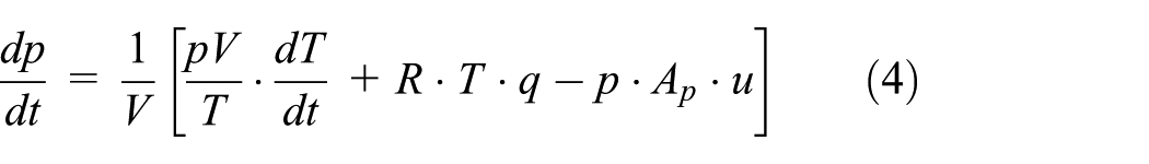
where p (Pa), V (m3), and q (kg/s) stand for pressure, volume, and mass flow of ideal air, respectively.
Kinetic equation of the motion of pistons
Simplified forces on the pistons are shown in Figure 2, which can be analyzed according to the Newton’s Second Law. In addition, the friction force is considered to be the total pf viscous frictions and coulomb frictions, which is shown in equation (6).

All simplified forces on the pistons of the air-liquid pressurization convertor.
Motion equation of the pistons can be built as equation (5)
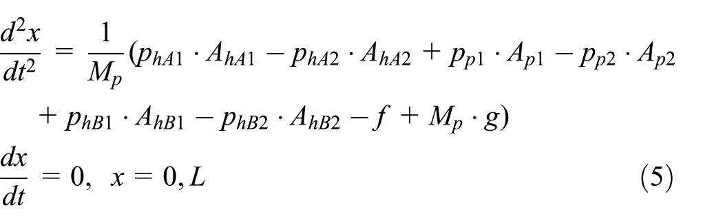

where Mp (kg) is the mass of the piston; x (mm) is the displacement of the piston; AhA1 (mm2) and AhA2 (mm2) stand for the equivalent areas of hydraulic piston A in the first chamber (upside of the pistons) and the second chamber (downside of the pistons) of liquid cylinder A, respectively; AhB1 and AhB2 stand for the equivalent areas of hydraulic piston B in the first chamber and the second chamber of liquid cylinder B, respectively; and Ap1 and Ap2 mean the equivalent areas of pneumatic piston.
PhA 1 (MPa) and PhA2 (MPa) stand for the hydraulic pressures in the first and second chambers of liquid cylinder A, respectively; PhB1 and PhB2 are hydraulic pressures in the first and second chambers of liquid cylinder B, respectively; and Pp1 and Pp2 are the pneumatic pressures in the first and second chambers of air cylinder, respectively.
What is more, f (N) is the friction force; Fc and Fs are force of coulomb friction and maximum static force of friction, respectively; L (mm) stands for the piston stroke; and C (N/m/s) is the viscous friction factor.
Pressure and flow equations of hydraulic system
Continuous equations in the driving chambers can be gotten as follows


In addition, the liquid volume flow flowing past check valves can be written as follows

where QAin (L/min) and QAout stand for the input and output volume flow in hydraulic chamber A, respectively; QBin (L/min) and QBout stand for the input and output volume flow in hydraulic chamber B, respectively; β (MPa) is the effective bulk modulus; Cd is the flow factor of orifice of check valve; and ρ (kg/m3) is the density of hydraulic oil.
Equations of the hydraulic motor
Figure 1 shows that the upper side of hydraulic motor is directly connected to outlet of the hydraulic chamber, and the pressure in the downstream oil tank is almost equal to the barometric pressure. Basic equations, which are shown in equations (10) and (11), including the continuous torque can be summarized as the equilibrium equation

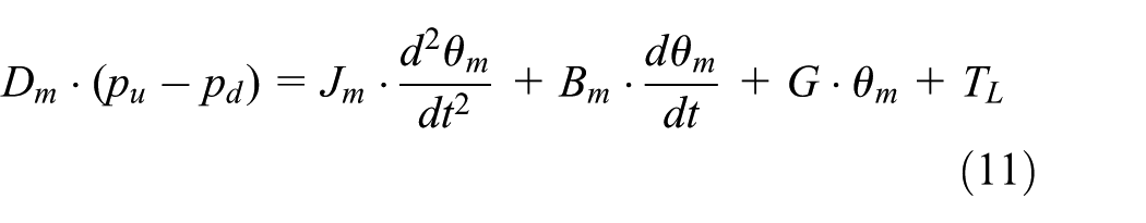
where qmotor (L/min) is the hydraulic motor flow; Cim and Cem are the factors of internal and external leakage, respectively; pu (MPa) and pd (MPa) are the motor upstream and downstream pressures, respectively. For the load system, Jm (kg mm2) is the inertia factor, Bm (kg mm2/s) is the viscous damping factor, and G (kg mm2/s2) is the spring stiffness factor; for the motor, θm (r/min) stands for motor output rotate speed. In addition, V0 (mm3) is the whole volume of motor chamber and TL (N mm) is the whole other external load.
Experimental demonstration of the model of sustainable energy automobile
In order to demonstrate the model supported above, an experimental station of automobile with air-liquid pressurization convertor was set up, which can be seen from Figures 3 and 4. The experimental station primarily includes an air-liquid pressurization convertor as the power unit and a hydraulic motor as the output actuator. On the main output road, we adopted a sensor which can test the output pressure approximately equal to that on the outlet of hydraulic motor. A flow sensor which is on outlet pipeline is connected to upstream of hydraulic actuator. The system safety threshold pressure can be set up by regulating the overflow valve in the system outlet part. Under normal circumstances, the hydraulic flow can hardly pass through the overflow relief valve, and flow sensors can measure almost the entire flow of the main road, by the way of motor. When the system pressure is too high because of the probable mechanical overload, hydraulic flow is about to pass through the relief valve instead of the motor, which to some extent will affect the experimental results. And an encoder mounted on the motor shaft can measure the real-time rotate speed.

Schematic diagram of the sustainable energy automobile test station.

Experimental station of sustainable energy automobile.
During the experiment, a relative low-power motor which drives a tiny load is chosen considering the safety property and output power matching of the air-liquid converter and hydraulic motor. Regulator is approximately set up to 1.56 MPa, which ensures most of the exhausting flow to be inputted to the hydraulic motor. Pneumatic input pressure is approximately set up to 0.67 MPa. Next, adjust the key parameters of the model for approaching actual practical working condition, and then the simulation results can be gotten in certain circumstances. Simulation and experimental curves of the output rotate speed and input flow are, respectively, shown in Figures 5 and 6.

Simulation and experimental flow curves.

Simulation and experimental rotate speed curves.
Figure 5 shows the flow comparison figure of the simulation and experimental results. We can see that the simulation result is consistent with the experimental one, which demonstrates the mathematical model built above. Both the simulation and experimental curves are similar to pulse curve. The inertia of the hydraulic system makes the experimental result more continuous. Under the effect of the accumulator, the disturbance caused by the high stiffness of hydraulic system during direction switch of the air-liquid pressurization convertor will reduce much.
Figure 6 shows that trend of the experimental curve is basically consistent with that of the simulation one. In Figure 6, the simulation curve top of the amplifier is significantly higher than the experimental value. Moreover, the simulation data are much smoother than the experimental results. The reason of the higher curves is that when inside pressure of the power system is large enough for relief regulator opening, not all the hydraulic flow will pass through the motor, and that will limit the output rotate speed of the motor. What is more, encoder sensitivity limit results in the sharp points of the experimental results.
Analysis of dynamic characteristic of the working automobile
Working condition and operating life of the hydraulic system vastly rely on the stability and comfort level of its dynamic characteristics. For improving the working performance of sustainable vehicle, we carried out researches on the influencing factors of the automobile system. Recent studies draw a conclusion that parameters such as input air pressure (pin), the hydraulic orifice (R), the piston area ratio (An), and the piston stroke (L) in the pneumatic and hydraulic cylinders will mostly influence the dynamic characteristics of the air-liquid pressurization convertor. In order to illustrate the influence, each parameter changes for comparison under the condition that the other parameters remain stable.
Considering the factors which can affect the working lifetime of the power system mainly include output flow and pressure of the hydraulic chamber, we studied the dynamic characteristics of them. Output flow is directly created by the extrusion of the piston during the moving time, and the flow through the hydraulic motor establishes the pressure based on the mechanical load. Pressure of the hydraulic system is directly determined by the mechanical load which can be simplified to moment of inertia and frictional damping. We take the average output flow and pressure values of each working process. The average output flow and pressure can directly reflect the dynamic capability of the power system. What is more, we calculated variances of the output flow and pressure which reflect the volatility of the dynamic characteristics and affect the lifetime of the automobile.
Effect of piston stroke on the dynamic characteristics of the system output
Piston stroke is always utilized to reflect the working performance of air-liquid pressurization convertor. In the simulation of this part, when area ratio (n) is set at 8, input pressure (pin) is set at 0.6 MPa, oil orifice (R) is set at 2.5 mm, and piston stroke (L) is set to 700, 900, and 1100 mm, and the working dynamic performances are analyzed as follows.
Figure 7 shows the output torque curve of the power system. The curve of the output torque starts to rise at first and then declines sharply when gets a top value. This is because the output torque is mainly directly obtained by the output pressure which is directly determined by the external load. At first, when the output pressure is below the breakout pressure of the hydraulic motor, the pressure keeps rising as the piston keeps moving and compressing the chamber space. This process will not last long because the stiffness of the hydraulic oil is really high. When the pressure gets the breakout value, the hydraulic motor starts the revolving work, and then the mechanical load reduces a lot as the inertia load and the system damp directly make up the pressure between the outlet and inlet ports in the hydraulic motor. So the torque–time curves present statement as shown in Figure 7.
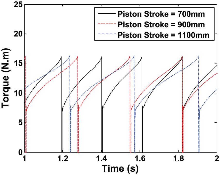
Output torque–time curves affected by piston stroke.
As shown in Figure 8, curves of rotate speed are similar to those of the output torque. This is because the rotate speed is related with the motor’s output flow which is immediately obtained by orifice throttle formula, and the pressure between the output chamber and inlet port of the motor directly makes up the output flow through the orifice of the chamber.

Output rotate speed–time curves affected by piston stroke.
From Figures 9 and 10, in the system, longer the piston stroke is, higher the average torque and rotate speed are, but the rising trend of the curves will reduce gradually. The torque variance and the rotate speed variance of the power system will reduce apparently. So a relatively longer piston stroke is benefit for extending the fatigue life of the power system. But an over-long stroke will reduce the system efficiency.
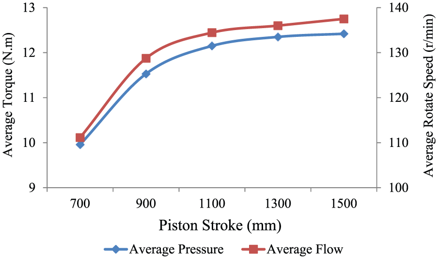
Average torque and rotate speed trend curves affected by the stroke of pistons.

Torque and rotate speed variance trend curves affected by stroke of pistons.
The effect of area ratio on system output dynamic characteristics
Area ratio directly determines the extent of the pressurizing. In the automobile system simulation, when input pressure (pin) is set at 0.6 MPa, the piston stroke (L) is set at 900 mm, oil orifice (R) is set at 2.5 mm, and area ratio (n) is set at 6, 8, and 10, the system output dynamic characteristics are analyzed.
As shown in Figure 11 and 12, it can be seen that area ratio will influence the output dynamic characteristics much more comparing with piston stroke. In addition, when area ratio is set to 8, sharp points will exist in the curves during every working circle time. But when the area ratio is set higher, the sharp points will disappear which means the dynamic characteristic is improved.
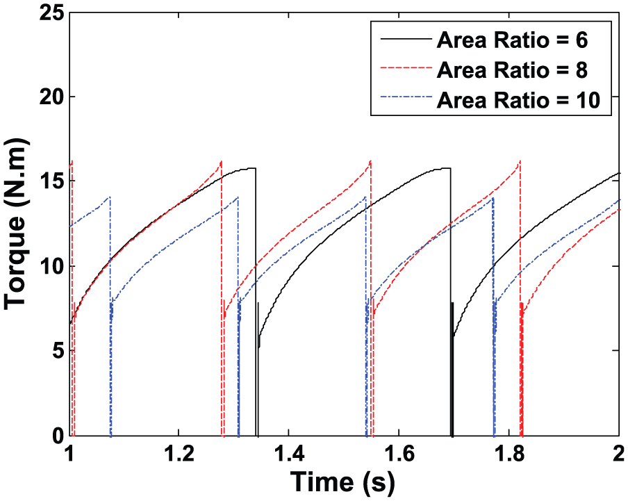
Torque–time curves affected by area ratio.

Rotate speed–time curves affected by area ratio.
From Figures 13 and 14, the average torque and rotate speed curves rise at the beginning and then reduce a lot. The highest point is at the time when the area ratio is set at 8. Similarly, torque and rotate speed variance curves reduce firstly and then increase, and the lowest point is when the area ratio is 8. So the ratio of the areas is recommended to be set to approximately 8, and setting a little higher to avoid the appearance of the sharp points. Then, the system output capacity is the highest and the dynamic characteristics are the best, which ensures the longest system lifetime.

Average torque and rotate speed trend curves affected by area ratio.
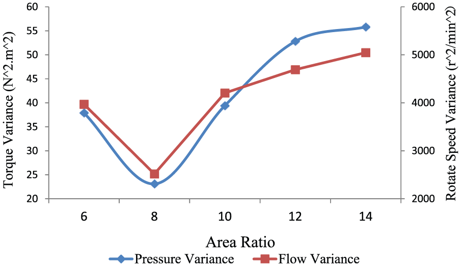
Torque and rotate speed variance trend curves affected by area ratio.
The effect of oil orifice on system output dynamic characteristics
In the simulation, when input pressure (pin) is fixedly set at 0.6 MPa, area ratio (n) is set at 8, and piston stroke (L) is set at 900 mm, and the orifice (R) of the hydraulic chamber at 2.5, 3.0, and 3.5 mm, the system working dynamic characteristics is analyzed.
Figures 15 and 16 show the system working characteristics influenced by the orifice of the hydraulic chamber. It can be seen that the effect of the orifice value is relatively high. According to oil through orifices throttling principle, the bigger the orifice is, the larger output flow coefficient is. When the orifice is set larger, the output flow will be directly promoted, and then we will obtain higher rotate speed. As long as the output flow is relatively high, the piston will accelerate the speed of the cycle.

Torque–time curves affected by orifice.
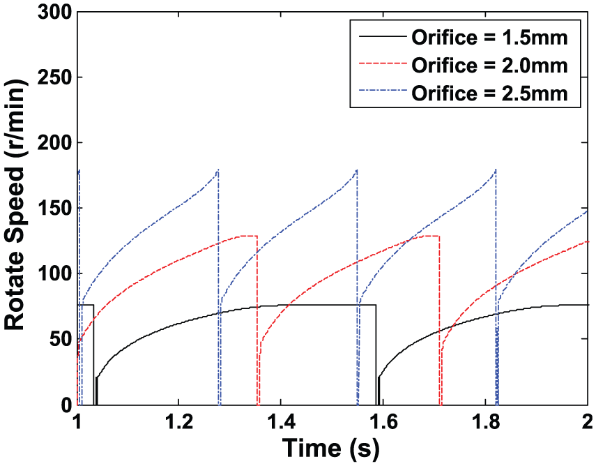
Rotate speed–time curves affected by orifice.
As shown in Figures 17 and 18, larger orifice will promote the system output capacity, including higher output torque and system rotate speed, which will allow the convertor system to drive a larger mechanical load. But setting the orifice too big will break the theory of orifice throttle, which will block the pressure building of the hydraulic system.

Average torque and rotate speed trend curves affected by orifice.

Torque and rotate speed variance trend curves affected by orifice.
The effect of input pressure on system output dynamic characteristics
Input air pressure is the energy source of the whole system. Fixedly, when the area ratio (n) is set at 8, and the orifice (r) is set at 2.5 mm, the input pressure (pin) is set at 0.5, 0.6, and 0.7 MPa, the dynamic characteristics of the high voltage transformer of the hydraulic motor are studied. As shown in Figures 19 and 20, input pressure will hardly influence the output dynamic characteristics, except the shading increase in the top of the curves with the increase in the input power.
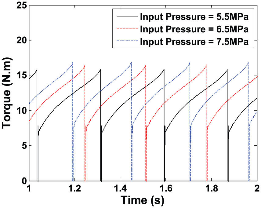
Torque–time curves affected by input pressure.

Rotate speed–time curves affected by input pressure.
According to Figures 21 and 22, average output torque and rotate speed will relatively improve with the rise of the input air pressure. But the pressure and flow variance of the output chamber are basically not under the influence of the input pressure. So from the point of the output side, the input air pressure will not affect the lifetime. Meanwhile, the input air pressure should be set appropriate to ensure the output efficiency. Considering the results of figures together, input pressure is considered to be 0.65 MPa under the condition in this article.

Average torque and rotate speed trend curves affected by input pressure.

Torque and rotate speed variance trend curves affected by input pressure.
Conclusion
This article aims to set the foundation for the improvement of the dynamic control characteristics of sustainable energy vehicle. First, model of sustainable automobile with nonlinearity was proposed and the output working dynamic control method was studied by analyzing the influence of the key structure parameters. Finally, the results can be concluded as follows which can be the control methods for the output dynamic characteristics:
The simulation results are greatly consistent with experimental ones, which demonstrate the system model built above to be greatly effective.
Piston stroke is one of the key parameters that affect the system dynamic characteristics in the structure model of the sustainable energy automobile. Longer piston stroke will be benefit for the dynamic property within the limit of the enough high output power and efficiency.
Area ratio is considered to be set to be higher than 8, which will ensure better dynamic characteristics including higher and smoother output torque and rotate speed. What is more, it can improve the system stability by avoiding the sharp points.
A bigger orifice can greatly improve the characteristic property of power system. Meanwhile, the orifice of oversize will make the principle of the throttling hole invalid.
Lifting the input air pressure will apparently promote the output torque and rotate speed characteristics, but a very high input pressure will cause over shocks of the characteristics. Under the condition in this article, proper input pressure can be 0.65 MPa.
This article provides a reference for optimizing the dynamic characteristics of sustainable energy automobile, especially for the field of compressed air-powered vehicle with air-liquid pressurization convertor.
Footnotes
Academic Editor: Nasim Ullah
Declaration of conflicting interests
The author(s) declared no potential conflicts of interest with respect to the research, authorship, and/or publication of this article.
Funding
The author(s) disclosed receipt of the following financial support for the research, authorship, and/or publication of this article: The research work presented in this article is financially supported by the National Natural Science Foundation of China (grant 51375028).