
Abstract
Based on the obtained mathematical models of straight-line gears, this article focuses on the investigation of fluid delivery and trapped volume performances of Truninger gear pumps. Considering the nonlinear relationship in mesh movement of straight-line gears, it is hard to derive explicitly solvable formulas of displacement and trapped volume with traditional methods. A discretization approach is proposed to obtain the numerical solutions. Then, the performances of fluid delivery and trapped volume are discussed. The results show that the trapped volume of Truninger gear pumps only has an expansion process, which avoids the pressure rise caused by the compression of trapped volume and has no contribution to the fluid delivery of pumps. To design Truninger gear pumps with a good delivery capacity, it is practical to choose a small tooth thickness, a large tooth number of the pinion, and a large profile angle with the proper choice of addendum coefficient and dedendum coefficient. Taking the example in this article for illustration, it may choose a tooth thickness of 3 mm, a tooth number of the pinion of 15, a tooth number of the internal gear of 18, a profile angle of 24°, an addendum coefficient of 0.66, and a dedendum coefficient of 0.9.
Introduction
Hydrostatic pumps are the heart component in fluid power systems, which convert mechanical energy into hydraulic energy to do useful work. With the advantages of simple structure, low price, insensibility to contaminate, and so on, gear pumps are the most often employed type among the hydrostatic pumps. Recently, the application area of gear pumps has covered the low pressure, the medium pressure (150–210 bar), and also the high pressure ranges (over 300 bar). 1 However, the noise problem of gear pumps is always troubling the users, in which the main part is the fluid noise caused by large flowrate pulsation and significant trapped fluid phenomenon. Therefore, with more and more attention paid to comfortable working conditions, gear pumps are commonly not the favorite choice in modern society. 2
In order to get quiet-operating gear pumps, many researches on gear pumps including internal gear pumps and external gear pumps are carried out. Manring and Kasaragadda 2 analyzed the instantaneous flowrate of external gear pumps with different tooth numbers for the driving and driven gears and indicated that increasing the tooth number of the driving gear can achieve a lower flowrate pulsation. With the use of AMESim, Casoli et al. 3 built a fluid dynamics model of external gear pump. This model made it possible to evaluate flowrate pulsation and volumetric efficiency of the pump conveniently. Based on the control volume approach, Huang and colleagues4,5 obtained the flowrate formulas of external gear pumps and external helical gear pumps, and the effects of the gear design parameters on the displacement and flowrate pulsation of these pumps are investigated. Recently, more advanced numerical models were built to describe the dynamic behavior of external gear pumps by lumped parameter approaches. Edge and colleagues6,7 developed a model of transient pressure of the meshing zone by a two-volume approach for the external gear pumps and motors. The leakage passages were represented by variable equivalent turbulent restrictors, whose flow area is dependent on the design parameters of relief groove and backlash, and the positions of the gears. With the same approach, Borghi et al. 8 and Wang et al. 9 also investigated the transient pressure of the external gear pumps and motors during the meshing process. These researches are very helpful to understand the phenomenon of pressure ripple and cavitation in the trapped volume of the external gear pumps and motors. Mucchi and colleagues10–16 proposed a nonlinear lumped kineto-elastodynamic model for external gear pumps, including the main phenomena during the pump operation and their interactions. Experimental and simulation results show that this model is a very useful tool to predict the dynamic behavior of external gear pumps, such as instantaneous flowrate, pressure ripple, vibration, and noise. Similarly, the research group of Vacca and colleagues17–20 also presented a lumped parameter model for the simulation of external gear pumps, which takes into account the micro-motions of internal mechanical parts and of thermal fluid–structure interaction to describe the instantaneous gap geometry at micro-level scale. The simulation and experiment verified the matched results on the tooth space volume pressure, the instantaneous delivery pressure ripple, and the effects of cavitation. In the meantime, with the essential merit of low flowrate pulsation, 1 internal gear pumps become the most promising quiet-operating gear pumps and attract a lot of interest from researchers. Colbourne 21 and Bead et al. 22 discussed the effects of the profile parameters on the flowrate performances of gerotor pump, which is a special kind of internal gear pumps. Gamez-Montero and Codina23,24 investigated the volumetric characteristics of gerotor pumps by the application of simulation and experiment methods. However, due to the lack of crescent-shaped filler, gerotor pumps cannot achieve a high operating pressure and are usually employed in low pressure occasions (below 15 MPa). Consequently, people focused attention on internal gear pumps with crescent-shaped filler, which can work well at pressure as high as 31.5 MPa. To describe briefly, the internal gear pumps mentioned in the following sections refer to the internal gear pumps with filler. With the advantages of interchangeability, insensibility to the variation of the center distance, and low manufacturing cost,25,26 involute internal gear pump is the most common type in the market. Ichikawa 27 derived the flowrate formula of involute internal gear pump by a torque approach and verified that internal gear pumps own better performances on flowrate pulsation and trapped fluid than external gear pumps. It is seen from Mimmi and Pennacchi’s 28 work that involute internal gear pumps have less flowrate pulsation and trapped fluid when the tooth number of pinion is close to that of internal gear. Zhou and Song 29 presented the investigations on the conjugated involute internal gear pumps, which has an internal gear with the whole profile completely conjugated to that of the pinion, and the results indicated that the conjugated involute internal gear pumps have a better performance than the conventional involute internal gear pumps.
As mentioned above, it is clear that the gear pairs will take the direct effect on the performances of gear pumps, especially on the flowrate pulsation and trapped fluid, both of which are relevant to the fluid noise of pumps. Therefore, a good design of gear pairs is essential for gear pumps operating quietly. To achieve this aim, Truninger 30 developed a special type of internal gear pump, the conjugated straight-line internal gear pump, also called Truninger gear pump (Figure 1). This pump includes a pinion with straight-line profile and an internal gear with profile conjugated to that of the pinion. Also, there is a crescent inside the gear pair to isolate the discharge chamber from the suction chamber. According to the demonstration by Truninger, 30 these straight-line type profiles lead to a smaller trapped volume, a smaller variation of trapped volume, and a longer service life than the involute internal gear pumps. Although the Truninger gear pumps have such extraordinary performances in the fluid noise and service life, few literatures have been found for the systematical investigation on the flowrate characteristics of Truninger gear pumps. In the previous article, 31 the authors derived the mathematical models of the conjugated straight-line internal gear pairs and also carried out overcutting and interference analysis based on the gearing theory. 32 With those mathematical models, this article presents a discretization approach to obtain the fluid delivery and trapped volume performances of Truninger gear pumps. We expect that this research should be helpful for the design of internal gear pumps with a low noise level.

Cross section of Truninger gear pumps.
Mesh characteristics of the conjugated straight-line internal gear pairs
As we all know, gear pumps complete the fluid delivery process by the mesh movement of gear pairs, which causes a change of cavity volumes between gears and chambers. Therefore, the mesh characteristics of gear pairs directly decide the flowrate characteristics of gear pumps. Here, in order to study the mesh characteristics of gear pairs, the line of action should be obtained first, which is the locus of contact points between the tooth surfaces of gear pairs.
Before the derivation of the line of action, the mathematical models of the conjugated straight-line internal gear pair obtained in the Song and Zhou 31 are listed in the following


where x1 is the x-coordinate of the point on the profile of the pinion, s is the tooth thickness, β is the profile angle, z1 is the tooth number of the pinion, z2 is the tooth number of the internal gear,
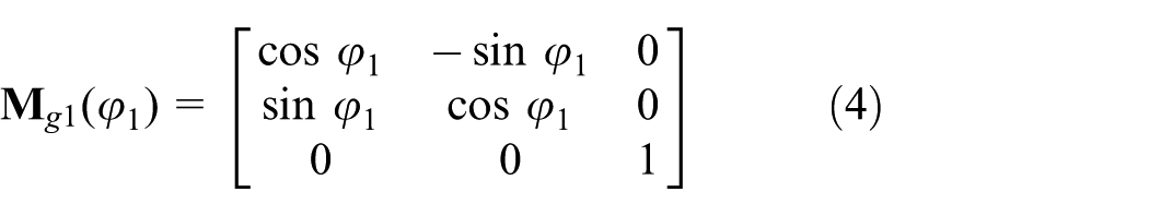
Based on the theory of gearing, 32 the line of action can be derived from the models of the gear pair by coordinate transformations, as represented by equation (3)

where ϕ1 is the rotation angle of the pinion,
Considering the necessary condition of

where r1 is the pitch radius of the pinion and y1 is the y-coordinate of the point on the profile of the pinion.
Combining equations (1)–(3), the line of action can be obtained.
Meshing process analysis
With equations (1), (2) and (5), the meshing process of the conjugated straight-line internal gear pair, with the pinion rotating clockwise, can be demonstrated by Figure 2. The line of action is curve AB and the contact point moves along the curve AB during the meshing process. To describe clearly, one tooth pair is taken for the illustration, part pinion tooth of which is filled with shadow lines, and the contact points are marked by hollow circles. Then, the meshing process can be illustrated as follows:
The target tooth pair comes into meshing at point A.
At this moment, the target tooth pair meshes at point C. As gears continue rotating, the contact point moves along curve AB.
The second tooth pair starts meshing at point A, while the target tooth pair meshes at point D. From then onward, there are two contact points simultaneously.
The second tooth pair meshes at point E, which is very close to point A, the start point of curve AB. At the same time, the target tooth pair meshes at point B, the end point of curve AB, which indicates the target tooth pair is going to finish meshing.

Meshing process of one tooth pair: (a) the target tooth pair comes into meshing, (b) the target tooth pair goes meshing, (c) the second tooth pair comes into meshing, and (d) the target tooth pair ends meshing.
Clearly, the meshing movement mentioned above decides the delivery process by one tooth pair. With the assumptions that there is backlash between the meshing teeth and no relief groove in the pump, the effective delivery process by one tooth pair occurs from Figure 2(a)–(c) while the remaining process from Figure 2(c) and (d) is the process of trapped volume. What is more, it is clear that the trapped volume between two contacting tooth pairs is quite small.
Overlap analysis
Besides considerations of avoiding overcutting and interference, 31 there must be two tooth pairs in contact simultaneously to obtain a stable operation of the conjugated straight-line internal gear pair. For conventional involuted gears, the index of overlap coefficient is introduced to describe the meshing status of gears, which should be larger than 1. Since there are different tooth profiles, the calculation of overlap coefficient of the involuted gears cannot be used for the conjugated straight-line internal gear pair. As far as the authors’ knowledge, there are few articles about the overlap analysis of the conjugated straight-line internal gear pair. Thus, before the investigation of fluid delivery and trapped volume performances, an overlap analysis of the conjugated straight-line internal gear pair is presented as follows.
With the pinion rotating clockwise, Figure 3 shows the moment when the gear pair has two contact points. Obviously, the first contact point is point B, while the second contact point is point M. And, point M locates in the line of action, curve AB, and also in the tooth profile of the pinion, line ab. Therefore, equations (6) and (7) should be satisfied


where θb is the angle of ∠bO1B, θl is the angle of ∠AO1B, and θM is the angle of ∠MO1B.

Moment with two contact points at the tooth profiles.
Then

Here

where θt is the angle of ∠aO1B and equals the value of 2π/z1.
With equations (8) and (9), the condition to get two contact points can be given by equation (10)

where


Here, (xa, ya), (xb, yb), (xA, yA), and (xB, yB) are the coordinates of points a, b, A, and B, respectively, which can be obtained from the mathematical models of the gears, as demonstrated by equations (1) and (3).
In the following part, a control volume approach is applied to derive the instantaneous flowrate formula of Truninger gear pumps. And, some indices, such as displacement, displacement per unit area, flowrate pulsation coefficient, maximum trapped volume, and change rate of trapped volume, are introduced to evaluate the flowrate characteristics of Truninger gear pumps.
Fluid delivery and trapped volume performances of Truninger gear pumps
Derivation of the instantaneous flowrate formula
The control volume approach is often used to derive the instantaneous flowrate formula of gear pumps.2–5,21–24,28,29Figure 4 shows the two control volumes, V1 and V2, built for the pinion and the internal gear, respectively. With hypotheses of incompressible fluid, no fluid leakage and rigid parts of the pump, the discharge volume of fluid, dV, equals the difference between the input volumes, dVi1 and dVi2, and the output volumes, dVo1 and dVo2, as represented by equation (13)

where


Control volumes for Truninger gear pumps.
Here, the axial thickness of the gear is considered as a unit thickness. And, ra1 is the addendum radius of the pinion, ra2 is the addendum radius of the pinion, rf1 is the distance from the contact point to the pinion center, rf2 is the distance from the contact point to the internal gear center, and ϕ2 is the rotation angle of the internal gear.
Given the fundamental law of gearing, it is known that

where r2 is the pitch radius of the internal gear and ω1 is the angular velocity of the pinion.
Equations (13)–(15) yield the instantaneous flowrate formula of the pumps

Here

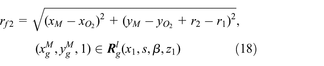
where (xM, yM) is the coordinate of contact point M.
Calculation of the displacement
The volume delivered by one tooth pair can be obtained by equation (19)

where tAD is the lasting time for the contact point moving from point A to point D.
Equation (19) yields

where ΔϕAD is the rotation angle of the pinion during the period of tAD.
As shown in Figure 2, the conjugated straight-line internal gear pairs have a nonlinear line of action. Then, different from the involute gear pumps, 29 the instantaneous flowrate cannot be expressed as a function including one time-dependent variable. What is more, as demonstrated in Figure 5, there is no explicit relationship between rotation angles of the pinion and the contact point, which are represented by ϕM and ψM, respectively. In Figure 5, in order to have a clear demonstration, besides the line of action, only addendum circle and working profile of the pinion are drawn. Here, the moments when gears contact at point A and point M are represented by the solid line and the dashed line, respectively. Since point M has a position moving nonlinearly, there is no explicit relationship between ϕM and ψM, which indicates that the flowrate is not an explicit equation of ϕ1. Therefore, it is hard to derive an explicit formula from equation (20).

Relationship between rotation angles of the pinion and the contact point.
According to Song and Zhou, 31 with the known design parameters, the geometrical model of gears at a certain moment can be obtained by MATLAB and the geometrical model is composed of a lot of discrete points. Therefore, it is possible to determine the point infinitely close to the real contact point. Then, with the coordinates of this obtained point, the corresponding instantaneous flowrate value at this moment can be calculated. Here, a discretization approach is presented to solve equation (20) as represented by equation (21)

where QϕA + iΔϕ1 is the instantaneous flowrate at the rotation angle of ϕA + iΔϕ1 and ϕA is the rotation angle when the pinion starts meshing. And

where ϕD is the rotation angle when the pinion ends meshing, Δϕ1 is the rotation angle step of the pinion, and n is a natural number whose value is relevant to the value of Δϕ1.
It is known that the geometrical model obtained by the mathematical models corresponds to the moment when the gears are not meshing at the beginning contact point, 31 as shown in Figure 1. Considering equation (21) that calculates the flowrate from the moment when the gears start meshing, it needs to calculate the angle of the pinion rotating from the mesh start moment to the moment, as shown in Figure 1. Here, for reducing the number of variables, we define this rotation angle as ϕA. And, it does not influence the result.
Before the calculation of ϕA, it needs to determine the position of the contact point at a given moment. Clearly, the intersect point between the profile and the line of action is the contact point. Considering these two curves consisted of discrete points, the contact point can be obtained by the method illustrated in Figure 6, as follows:
Choose an arbitrary point, p1, from the working pinion profile, line ab.
Calculate the difference dx between the x-coordinates of points p1 and p2. Here, point p2 is an arbitrary point from the line of action AB.
For point p1, curve AB can produce a set of the absolute value of dx. The point corresponding to the minimum value of the set is considered aligned with point p1 in the y-coordinate axis direction, which is marked as point p3. Then, calculate the difference dy between the y-coordinates of points p1 and p3.
Using the above three steps, line ab can produce a set of absolute value of dy. The point corresponding to the minimum value of the set is considered as the intersect point P.

Determination of contact point at a given moment.
With the obtained contact point, Figure 7 demonstrates the algorithm to determine the value of ϕA, given as follows:
Assume the initial value of ϕA as 0.
Rotate line ab anticlockwise with an angle of ϕA, initial value of which is Δϕ1, and then obtain the model of the new line ab, as represented by equation (21)

where

Determine the intersect point of line ab and curve AB with the method demonstrated in Figure 6. To illustrate clearly, this method is expressed as follows

where M is the intersect point of line ab and curve AB.
If the x-coordinate and the y-coordinate of point M are simultaneously not larger than those of point A, which indicates point M locates between point A and point B, increase the value of ϕA by a step of Δϕ1 and repeat the above course. If not, quit the iteration and consider point M coincident with point A. And, the value of ϕA at this moment is regarded as the solution.

Algorithm for determining the value of ϕA.
After obtaining the value of ϕA, equation (21) can be solved by a similar discretization method, as illustrated in Figure 8.
Define ϕr equals ϕA and the initial value of VZ is 0. Here, ϕr is the rotation angle of the pinion in the process of calculating volume delivered by one tooth pair.
Increase ϕr by a step of Δϕ1 and rotate line ab anticlockwise with an angle of ϕr, as represented by equation (26)

where
Obtain the intersect point M between line ab and curve AB by equation (25).
If the x-coordinate and y-coordinate of point M are not larger than those of point B simultaneously, calculate the value of instantaneous flowrate Q at this moment by equation (16) and add Vz by Q. Then, add ϕr by a step of Δϕ1 and repeat the above course. If not, quit this calculation.

Algorithm for calculating volume delivered by one tooth pair.
With the obtained value of Vz, the displacement of the pump can be given by equation (28)

Calculation of the trapped volume
According to Figure 2, the trapped process occurs from Figure 2(c) and (d). Just like the derivation of displacement mentioned above, it can be found impossible to obtain an explicit solvable formula of trapped volume. Similarly, a discretization approach is applied again to calculate the instantaneous trapped volume.
From Figure 9(a), it is easy to understand that the trapped area between curve1 and curve2, which intersect at two points A and B, can be obtained by equation (29)

where
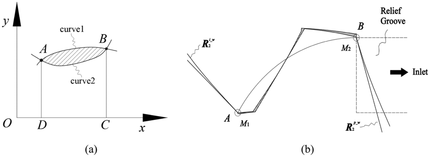
Principle of calculating trapped volume: (a) trapped area between two curves intersecting at two points and (b) trapped volume between the meshing tooth pairs.
According to the principles of integration and discretization, equation (30) can be obtained

where f(x) and g(x) are equations of curve1 and curve2, respectively; xA and xB are the x-coordinate of points A and B, respectively; Δx is the step of x-coordinate, and m is a natural number whose value is relevant to the value of Δx.
According to equation (30), the trapped volume of Truninger gear pumps, shown in Figure 9(b), can be calculated. Here,
As mentioned above, with the rotation of gears, points M1 and M2 move along curve AB, which leads to the variation of AM12. And, the trapped process ends when point M2 departs from point B. Therefore, Figure 10 gives an algorithm to calculate the variation of AM12, as follows:
Define the initial values of rotation angle ϕr and flag i as 0.
Make the value of ϕr equal the plus of ϕA and Δϕ1. Here, Δϕ1 is a step of rotation angle.
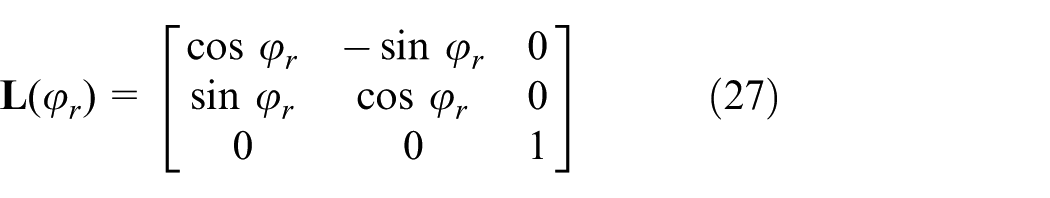
Rotate the profiles of the pinion and the internal gear, as represented by equation (31)

where

Determine the intersect points M1 and M2 of profile

If the x-coordinate and y-coordinate of point M2 are not larger than those of point B simultaneously, calculate the trapped volume between

where

where
Algorithm for calculating the variation of trapped volume.
Also

where xM1 and xM2 are the x-coordinate of points M1 and M2, respectively.
By substituting equations (35) and (36) into equation (34), the trapped volume at this moment can be obtained. Then, add ϕr by a step of Δϕ1 and repeat the above course until the x-coordinate and y-coordinate of point M2 are larger than those of point B simultaneously, which indicates the trapped process is done. If the x-coordinate and y-coordinate of point M2 are larger than those of point B at the beginning, it is clear that there is only one contact point, which indicates the gear pair cannot work for fluid delivery and the values of displacement and trapped volume are both 0.
Results and analysis
With the known parameters of the internal gear pair, the equations obtained above can be solved by a program written by MATLAB codes. Taking the internal gear pair whose parameters are listed in Table 1, for example, the developments of instantaneous flowrate and trapped volume with respect to the rotation angle of the pinion by one tooth pair are obtained and depicted in Figure 11.
Parameters of the internal gear pair.


Flowrate performances of delivery process by one tooth pair.
In Figure 11(a), the instantaneous flowrate delivered by one tooth pair has a pattern of similar parabola against the rotation angle of the pinion. The maximum value with a value of 4.15 cm3 occurs when a rotation angle reaches 15° from the meshing start position. And, the minimum value is 3.96 cm3 at the rotation angle of 30°, when the delivery process by the tooth pair is finished.
Figure 11(b) shows Truninger gear pump has a trapped volume increasing in an approximately linear pattern with the pinion rotating, which is different from the involute internal gear pump. 16 The maximum value is 0.012 cm3 at the rotation angle of 0.95° and the minimum value is 0.0018 cm3 at the beginning of the meshing. And, the rotation angle of the trapped process is 0.95°. Obviously, the trapped volume only has an expansion process while without a compression process. It is known that the compression of trapped volume can yield an extremely large pressure rise, 1 which induces the high noise level and weakens the service life of pump parts. Therefore, in comparison to the involute internal gear pumps, Truninger gear pumps have a better performance of trapped volume and are probable to have a lower operating noise.
Clearly, relief groove is needed to reduce the harmful effects of trapped volume on the pump, which also affects the fluid delivery process of gear pumps. 1 According to Figure 11(b), only the relief groove connecting the trapped volume to the inlet of the pump is needed, as demonstrated by the dotted lines in Figure 9(b), which can avoid the problems caused by cavitation during the expansion process of the trapped volume. Obviously, unlike the involute gear pumps, the trapped volume of Truninger gear pumps has no contribution to the fluid delivery, which has an effective fluid delivery process by one tooth pair stopping at the moment when the next tooth pair gets contacting. Subsequently, the instantaneous flowrate of Truninger gear pumps is depicted in Figure 12 (three tooth pairs), which demonstrates the flow ripple of the pumps.

Instantaneous flowrate of Truninger gear pumps by three tooth pairs.
To evaluate the influences of design parameters of gears, including tooth thickness, tooth number, profile angle, addendum coefficient, and dedendum coefficient, on flowrate characteristics of Truninger gear pumps, some indices are introduced, such as displacement, displacement per unit area, and flowrate pulsation coefficient. Here, definitions of the above indices, except displacement, are given in the following.
Displacement per unit area, qarea, equals displacement divided by the area of the dedendum circle of internal gear, as represented by equation (37). Compared to the displacement represented by equation (28), qarea is better to describe the delivery capacity of the pump taking account of gear pair dimensions
Flowrate pulsation coefficient, γpuls, is used to evaluate the flowrate fluctuation level of the pump and defined as follows

In the following analyses, based on the parameters listed in Table 1, one parameter is varied, while the other parameters keep the same at each time. By this way, the influence of the parameter on flowrate characteristics of the pump can be investigated. Here, the parameters should ensure that there are two contact points at tooth profiles with the help of equation (10). Also, possible overcutting or interference of teeth should be avoided by the means demonstrated in Song and Zhou. 31
Tooth thickness
In Figure 13, increasing tooth thickness makes displacement get larger while does not influence displacement per unit area and flowrate pulsation coefficient. According to Song and Zhou, 31 tooth thickness is proportional to the geometry dimensions of gears. Therefore, for gear pairs with a unit axial thickness, displacement is proportional to the square of tooth thickness. Since tooth thickness does not change the gear shape, displacement per unit area and flowrate pulsation coefficient keep constant. Briefly, on the condition of a large enough displacement, the pump with a smaller tooth thickness is better with considering the pump dimensions.
Influences of tooth thickness.
Tooth number
In Figure 14, displacement increases as the tooth number of the pinion increases, which is fairly insensitive to that of the internal gear. And, a large displacement per unit area and a small flowrate pulsation coefficient can be obtained by increasing the tooth number of the pinion or by decreasing the tooth number of the internal gear. Here, during the change of tooth number in this case, the tooth number difference should be larger than 2 for avoiding the interference of gears. 31 In brief, a small tooth number difference between the gears benefits displacement per unit area and flowrate pulsation coefficient at the same time.

Influences of tooth number.
Profile angle
According to equation (10), the profile angle should not be larger than 26.23° with the other parameters listed in Table 1, which makes two contact points to avoid the delivery failure of the pumps. Also, the profile angle should not be too small to get a bad transmission efficiency. Here, the profile angle changes from 20° to 26°.
In Figure 15, a large profile angle leads to a rise of displacement and displacement per unit area with a small flowrate pulsation coefficient. When the profile angle is large enough, at least 24° in this case, it almost has no influence on those three indices, which indicates a large profile angle is good to increase the delivery capacity and decrease the flowrate pulsation. For example, a profile angle of 24° is good in this case.
Influences of profile angle.
Addendum coefficient
Equation (10) shows that the addendum coefficient should not be less than 0.58 to obtain two contact points. Meanwhile, considering the problems of overcutting, 31 the addendum coefficient should not be too large. Hence, the addendum coefficient changes from 0.58 to 0.8 in this case.
In Figure 16, during the increment of addendum coefficient, both displacement and displacement per unit area have a similar reverse V shape while flowrate pulsation coefficient gets a similar V shape, which has a very little decreasing rate with the addendum coefficient smaller than 0.64. Here, an addendum coefficient of 0.66 gets a largest delivery capacity, while 0.64 getting a smallest flowrate pulsation coefficient. Therefore, a proper addendum coefficient may be a comprise solution, taking 0.66, for example, in this case.
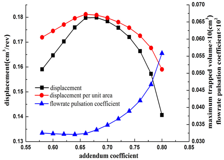
Influences of addendum coefficient.
Dedendum coefficient
On the contrary to addendum coefficient, dedendum coefficient should be large enough to ensure two contact points and not be too large to obtain an invalid tooth profile, which can be decided by equation (10) and reference 31, respectively. Here, the dedendum coefficient changes from 0.76 to 0.98 in this case.
In Figure 17, during the increment of dedendum coefficient, displacement varies in a similar downward parabola with a maximum value of 0.9 and flowrate pulsation gets large, values of which both distribute in a small interval. With respect to displacement per unit area, since the dedendum circle of the internal gear is independent of the dedendum coefficient of the pinion, it almost keeps constant since the change of displacement is very small. Obviously, the influences of the dedendum coefficient on delivery capacity are quite small.

Influences of dedendum coefficient.
Table 2 presents a clear summary of the above results. Here, the upward arrow means “increase,” while the downward arrow means “decrease.” To be simply described, “V shape” means the index increases first and then decreases. And, “reverse V shape” has the similar meaning.
Influences of gear parameters on flowrate characteristics of Truninger gear pumps.

Conclusion
With mathematical models of the conjugated straight-line internal gear pairs obtained in Song and Zhou, 31 this article has carried out an investigation of influences of gear parameters on flowrate characteristics of Truninger gear pumps by a discretization approach. From the above mentioned results and analysis, the following conclusions can be drawn:
The trapped volume of Truninger gear pumps increases in an approximately linear pattern with the pinion rotating, which only has an expansion process while without the compression process. Therefore, compared to involute internal gear pumps, Truninger gear pumps can avoid the extremely large pressure rise caused by the compression of trapped volume and are probable to have a lower operating noise. Also, without the compression process, the trapped volume of Truninger gear pumps has no contribution to the fluid delivery.
On the condition of a large enough displacement, increasing the tooth thickness has no good for increasing the delivery capacity, which leads to a large pump size.
Increasing the tooth number of the pinion obtains a large deliver capacity with a small flowrate pulsation coefficient. Increasing the tooth number of the internal gear has a slightly influence on displacement, with a small displacement per unit area and a large flowrate pulsation coefficient.
With values to ensure two contact points and a good transmission efficiency, a proper large profile angle does good to increase the delivery capacity with a rather small flowrate pulsation.
Considering the effective tooth overlap and valid tooth profile, a proper addendum coefficient is a comprise solution for concerning the delivery capacity. On the contrary, the dedendum coefficient has quite small influences on delivery capacity.
Briefly, Truninger gear pumps have no compression process of trapped volume, which indicates they may operate more quietly than the involute internal gear pumps. To design Truninger gear pumps with a good delivery capacity, it is practical to choose a small tooth thickness, a large tooth number of the pinion, and a large profile angle with the proper choice of an addendum coefficient and a dedendum coefficient. Taking the example in this article for illustration, it could choose a tooth thickness of 3 mm, a tooth number of the pinion of 15, a tooth number of the internal gear of 18, a profile angle of 24°, an addendum coefficient of 0.66, and a dedendum coefficient of 0.9.
Footnotes
Appendix 1
Academic Editor: Jianqiao Ye
Declaration of conflicting interests
The author(s) declared no potential conflicts of interest with respect to the research, authorship, and/or publication of this article.
Funding
The author(s) disclosed receipt of the following financial support for the research, authorship, and/or publication of this article: This research was supported by the National Natural Science Foundation of China (Grant No. 51175453) and the Project of Key Innovation Team of Zhejiang Province (Grant No. 2013TD14).