
Abstract
Axial piston pumps are very important to the hydraulic system on aircrafts, and their reliability plays critical role for ensuring the reliability and safety of aircrafts. The thickness prediction of the film between valve plate and cylinder block has received considerable concerns. This article presents a new dynamic seven-stage model for the thickness prediction of the film between valve plate and cylinder block in axial piston pumps. By dividing the rotation of the cylinder into seven stages, the complete analytical expression of the pressure distributions between valve plate and cylinder block is derived. The lubrication film forces and torques exerted on the cylinder block are then calculated and the film is determined by analyzing the complex dynamics of cylinder block. Experiments have been conducted and the results show that the proposed model is effective.
Keywords
Introduction
Due to the large power-to-weight ratio and high efficiency, axial piston pumps are widely used in the hydraulic systems of aircrafts. The failure of axial piston pumps may cause the breakdown of hydraulic system of aircrafts or even lead to catastrophic consequences. It has been found that large percent of the failures of axial piston pumps are caused by the wear between valve plate and cylinder block. 1 Therefore, the lubrication and wear condition between these components are very crucial to maintain the health of axial piston hydraulic pump.
Many attempts have been done on the dynamics and lubrication analysis of valve plate and cylinder block. Seeniraj and Ivantysynova 2 investigated the impacts of various valve plate design parameters on the pump flow ripple, oscillating forces, and volumetric efficiency, and the well-known program CASPAR was used to implement the explicit simulation. Kassem and Bahr 3 conducted a comprehensive study on the effect of triangular silencing grooves’ dimensions on the piston chamber pressure and pump flow fluctuation for the pump with the conical cylinder block. Mandal et al. 4 presented a new model which puts special emphasis on analyzing the effect of volume variation of silencing grooves, and the pressure within each silencing groove was explicitly solved. Ivantysynova and Lasaar5,6 optimized the gap design of piston/cylinder assembly in terms of piston shape and piston surface roughness, and the energy dissipation resulted from gap flow, and viscous friction force was proved to be reduced obviously due to the advanced gap design. Hong and Lee 7 performed a comparative study of two kinds of coatings on the improvement of the low-speed torque efficiency of a hydraulic piston pump. It was demonstrated that the tribological contact with coatings between cylinder and valve plate was improved significantly in comparison with uncoated plasma-nitrided one. The effect of TiN plasma coating on the surface of cylinder block was also investigated, and the friction and wear rate of valve plate in the low-speed range with mixed lubrication were thus reduced. 8 The lubrication characteristics between piston and cylinder were evaluated with contact ratio, 9 and it was proved that under low-speed and high-output pressure, the mixed lubrication is more likely to occur. The friction between piston and cylinder was also evaluated thoroughly.10,11 In order to predict the friction and flow under mixed lubrication between slipper and swash plate, a comprehensive model based on the Greenwood–Williamson model for non-lubricated rough surfaces and mean flow model was proposed and verified with experiments. 12
Bergada et al. 13 studied the pressure, flow, force, and torque between barrel and plate in an axial piston pump and validated the model with experiment. Considering a slipper design incorporating a groove on the slipper face, Bergada et al. 14 continued to study the hydrostatic and hydrodynamic behavior of an axial piston pump slipper with multiple lands based on an analytical approach. Later, he studied the lubrication film between valve plate and cylinder and made a complete analysis of axial piston pump leakage. 15 The effect of oil pressure and temperature on barrel film thickness was studied as well. 16 He also studied the effect of piston groove on the lubrication performance in hydraulic pumps via computational fluid dynamics (CFD) analysis considering piston force, leakage, and piston stability. 17
So far, most studies focused on the friction force and torque between the piston and the cylinder block, the pressure distribution and leakage, as well as the non-isothermal gap flow and the temperature distribution between the valve plate and cylinder. This article presents a dynamic seven-stage (DST) model for the thickness prediction of the film between the valve plate and cylinder block in the axial piston pumps. By dividing the rotation of the cylinder into seven stages and considering the squeeze effect of lubricating gap film, the silencing groove effect, and the contribution of the top transitional piston, the complete analytical expression of the pressure distributions between the valve plate and cylinder block is derived. The lubricating film forces and torques exerted on the bottom of the cylinder block are then calculated based on the intensive analysis of the dynamic angular range during one rotation period. The film thickness is determined by analyzing the complex dynamics of cylinder block. Besides the lubricating film forces and torques, other loads such as the time-dependent piston chamber pressure, the piston friction, the radial torques coming from slipper and swash plate, and the torques exerted by the cylinder block bearing are also taken into account.
The rest of this article is organized as follows. Section “Dynamic model of the variable lubricating film” presents the new analytical model of the lubricating film thickness between the valve plate and the cylinder block. The dynamic model is derived after calculating the force and torque exerted on the cylinder block. In section “Simulation results and experimental validation,” the simulation results of the film thickness are illustrated and compared with experimental measurements. Conclusions are drawn in section “Conclusion.”
Dynamic model of the variable lubricating film
It is difficult to directly calculate the thickness of the lubricating film between the valve plate and the cylinder block. However, during pump’s rotation, the gap between the valve plate and the cylinder block is filled with hydraulic oil. Since the valve plate is fixed to the pump case, the barrel-valve plate film shape and thickness will be determined by the position of cylinder block. Therefore, the lubrication film thickness can be calculated by analyzing the dynamic motion of cylinder block. In the following sections, the force and the torque between the cylinder block and the valve are first calculated. Other force and torque acting on the cylinder block are calculated and the whole model is built.
Force/torque analysis between cylinder block and valve plate
Analysis of pressure distribution
The general operating principle of axial piston pumps is shown in Figure 1. It can be seen that there are two large kidney-shaped ports on the inner surface of valve plate which are connected to the inlet and outlet ports of piston pump, respectively. The bridges between inlet and outlet ports separate out each of them. The pistons reciprocate in piston chambers, and the direction of motion of each piston changes when it steps over either of these bridges. The position of these two bridges is called the top-dead-center (TDC) and the bottom-dead-center (BDC), respectively, as illustrated in Figure 1(b).

The operational principle and concise geometry of an axial piston hydraulic pump: (a) front view and (b) left view of valve plate and local enlargement of the top transitional piston.
When the cylinder block is rotating, there is always a piston which overlaps with the outlet silencing groove and has not reached the outlet kidney port yet, and this piston is called the top transitional piston in this article. The local enlargement of the top transitional piston is shown in Figure 1(b). The pressure in this piston chamber rises at a certain rate due to the effect of outlet silencing groove, hence the effect of this piston on the fluid force and torque is different from that of other pistons and needs to be analyzed individually. The cylinder block is pressed against valve plate by a spring and is slightly tilted with respect to the valve plate with tilt angle
Before developing the model, the following assumptions are made:
The flow between the cylinder block and the valve plate is laminar (as the lubrication film between cylinder block and valve plate is very thin).
The fluid in the pump is Newtonian and incompressible.
The gap flow is isothermal and moves in radial direction.
The width of seal lands is small enough compared with the circumference and can be neglected.
General expression of the pressure distribution
The relationship between the pressure distribution and the film thickness can be described by the Reynolds equation. First, the Reynolds equation in cylindrical coordinates can be given by

Since the lubricating film thickness changes during the cylinder block’s rotation, the squeeze effect corresponding to the second term in the brackets on the right side of equation (1) is significant for elaborately depicting the pressure distribution between the cylinder block and the valve plate and must be considered as a dynamic model. Hence, equation (1) is integrated along both inner and outer seal lands of various grooves on valve plate. Since the tilt angle of cylinder block is very small, the fluid film thickness of any seal land is

where the average radius


Substituting equations (3) and (4) into equation (1) and computing the integral of both sides yields the general expression of the pressure distribution as

where the constants, for example, u and v, can be determined according to boundary conditions of corresponding seal lands.
The pressure distribution of the outer seal land of the outlet kidney port
The boundary conditions for the outer seal land of the outlet kidney port are

By substituting equation (6) into equation (5), the constants, for example, u and v, can be obtained as
Then, the pressure distribution of the outer seal land of the discharge kidney port can be calculated as
where
The pressure distribution of the inner seal land of the outlet kidney port
Similarly, the boundary condition for the inner seal land of the outlet kidney port is

The pressure distribution of the inner seal land of the discharge kidney port can be calculated as

where
The pressure distribution of the seal lands of the outlet silencing groove
The boundary condition for the seal lands of the outlet silencing groove is

The pressure distribution of the seal lands of the discharge silencing groove can be calculated as


where
The pressure distribution of the top transitional piston
Since the radial width of the piston kidney on the bottom of the cylinder block is the same as that of the discharge kidney port on valve plate, the geometry of the inner and outer seal lands regarding the top transitional piston is the same as that of the discharge port. Therefore, the boundary condition of the top transitional piston is

Substituting equation (14) into equation (5), the pressure distribution of outer seal land of the top transitional piston can be calculated as

The pressure distribution of inner seal land of the top transitional piston can be calculated as

To calculate Ptr_ext and Ptr_int, the instantaneous pressure ptr is needed. Assuming that when a piston leaves the inlet port groove, its pressure remains as ps until it begins to overlap with the outlet silencing groove. Once there is overlap between outlet silencing groove and the top transitional piston, the pressure in the piston chamber begins to rise. Figure 2 illustrates the start and end positions of the top transitional piston.
The geometry of the top transitional piston and the outlet silencing groove.
The relationship between ptr and the transitional piston angle

where
Equation (17) can be solved via numerical method and value of ptr can be obtained, and the initial condition is
Analysis of force/torque between cylinder block and valve plate
The force and torque between the cylinder block and the valve plate can be obtained by calculating the integral of certain pressure distribution over corresponding area on the valve plate. As the piston ports enter and then leave silencing groove and discharge kidney port continuously, the angular interval of integration will change with time. Assuming that when a piston leaves the discharge port, its pressure remains until the piston reaches the inlet silencing groove. Once the overlap between inlet silencing groove and piston occurs, the piston pressure drops to inlet pressure. The position of each piston is periodic, and Figure 3 lists the seven stages in one period, which starts when one piston is at the TDC and ends when the next adjacent piston reaches the TDC. Figure 4 illustrates the position of the piston passing the silencing groove. The total angular range of one period is 40°. The relevant dynamic angular limit of the three supporting regions in one period is shown in Table 1.

Position of all pistons in one period in the seven stages.

Position of the piston passing the silencing groove in one period.
The dynamic angular limit of the three supporting regions in one period.
The expressions of the fluid force and the torques with respect to the discharge kidney port can be given by


where the fluid force Fdis is in the negative direction of z-axis, and the torques, Mdis_X and Mdis_Y, are over the x-axis and y-axis, respectively. By substituting the pressure distribution in equations (8) and (10) into equations (18)–(20), we can have


It can be seen from equations (21) to (23) that all of them can be considered as the sum of four items. The first item reflects the effect of discharge pressure. The second item reflects the effect of inlet pressure. The third item reflects the effect of piston chamber, and the fourth item reflects the effect of silencing groove.
Similarly, expressions of the fluid force and the torques with respect to the discharge silencing groove and the top transitional piston can also be obtained. Then, the overall fluid force and torque exerted on the cylinder block can be calculated by

Other forces/torques imposed on the cylinder block
Besides the fluid forces and the torques between the cylinder block and the valve plate as mentioned in section “Force/torque analysis between cylinder block and valve plate,” there are some other forces and torques imposed on the cylinder block.
The force/torque resulted from piston chamber pressure
The cylinder block is mainly loaded by an oscillating force resulting from the pressure in the piston chambers. This force presses the cylinder block against the valve plate. It should be pointed out that the piston chamber pressure changes with time. Since the leakage between the piston and the cylinder block and the one between the slipper and the piston is of much lower order of value than the piston flow, the instantaneous pressure of the individual piston chamber can be calculated as
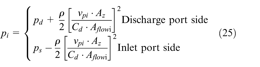
where Aflowi is a function of rotary angle

Friction force and torque on the piston
In addition to the force and torque resulting from the piston chamber pressure, friction force also exists between piston and cylinder which usually acts on the cylinder block in the direction of piston velocity. With the method proposed by Jeong and Kim, 11 the instantaneous piston friction force is
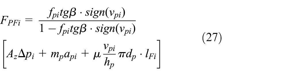
where fpi and api can be given by

All the related physical dimensions are illustrated in Figure 3. Both the outer and the inner piston friction coefficients
The radial torques from pistons
Other than all the force and torque discussed which are in the direction of z-axis, there exists some radial forces, for example, NOi and NIi, which are transmitted from the pistons to the cylinder block (see Figure 5). Based on the force equilibrium equation in y-direction and the torque equilibrium equation about the center of mating distance between the piston and the cylinder chamber, the reaction forces in radial direction can be given by 11
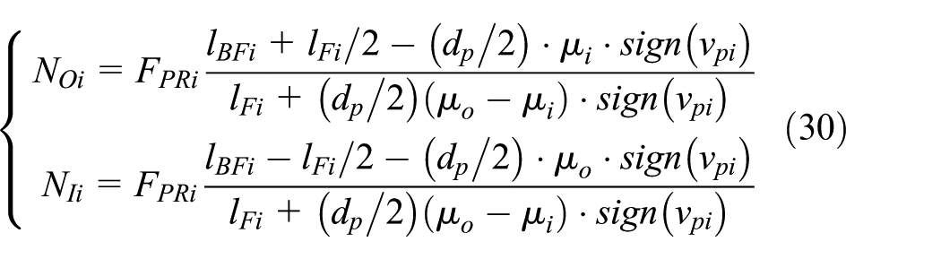
where


The geometry of the piston and the cylinder block.
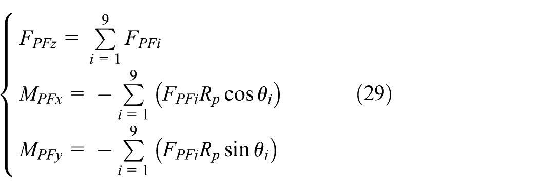
The centrifugal force on the pistons and the friction force produced by the sliding surfaces of slippers are small and thereby can be neglected. Then, the torque resulted from the piston radial forces NOi and NIi can be given by

Dynamics of the cylinder block
The dynamic model of cylinder block can be calculated based on all the force and torque exerting on the cylinder block as given by
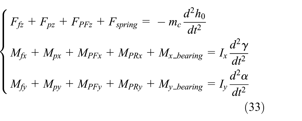
The moment of inertia

Simulation results and experimental validation
In order to validate the proposed model, we have considered a certain type of aircraft hydraulic piston pump, which was manufactured by Liyuan hydraulic corporation in Guiyang, Guizhou, China. The type of the pump was LY-YZB-73B. Some parameters of this pump are listed in Table 2.
Some parameters of the pump.

Simulation results
All the equations are solved in MATLAB®. The simulation condition is shown in Table 3. Figure 6 illustrates the resultant force and torques exerted on the cylinder block.
Simulation condition.


The resultant force and torques exerted on cylinder block.
Since the angular velocity of the cylinder block is 4000 r/min and the total range of one period (for the piston position) is 40°, the duration of each period is 1.667 ms. From Figure 6(a)–(c), it can be seen that all force and torques have two peaks in each period. The smaller peak appears at the end of Stage 1 when the top transitional piston passes the discharge silencing groove and begins overlapping with the discharge kidney port. The larger peak appears at the end of Stage 3, when one piston begins overlapping with the inlet silencing groove. For the smaller peak, during Stage 1, due to discharge silencing groove, the top transitional piston chamber pressure starts increasing from the inlet pressure ps but has not reached the discharge pressure pd yet. When the top transitional piston passes over the discharge silencing groove and begins overlapping the discharge kidney port, the chamber pressure will make a sudden rise to pd, and this will make the piston pressure force Fpz to rise suddenly and cause the smaller peak. For the larger peak, at the end of Stage 3, the piston inside the bottom bridge begins to move into the inlet silencing groove, and the chamber pressure will drop to inlet pressure ps rapidly. The film bearing force of this piston will as a result decrease, and this will cause the larger peak in the resultant force and torques.
The thickness of the lubricating film between the cylinder block and the valve plate is determined by the central film thickness h0 and the cylinder block tilt angle

Simulation results: (a) central thickness of the fluid film, (b) cylinder block tilt angle perpendicular to x-axis, (c) cylinder block tilt angle perpendicular to y-axis, and (d) film thickness of the outer seal land at TDC.
Figure 8 shows the distribution of the film thickness along the inner and outer seal lands on the valve plate under the conditions in Table 3. The plots start from y+ axis and the positive direction is counter-clockwise. The time average film thickness is calculated based on Figure 8 and is shown in Figure 9. The maximum film thickness appears on the discharge port side at 150°, and the minimum film thickness occurs at 330°. The time average film thickness of the inner seal land is smaller than that of the outer seal land in the range of 60°–240° and is greater in the rest of the whole range.

The results of dynamic film thickness simulation: (a) outer seal land, (b) inner seal land, (c) outer seal land (contour line), and (d) inner seal land (contour line).

Simulation results of average lubricating film thickness.
Experimental validation
To validate the proposed DST model, a set of tests for a typical axial piston pump was carried out, and the experimental device is shown in Figure 10. In these tests, the rotation speed was 4000 r/min, and the output pressure of the pump was 21 MPa.
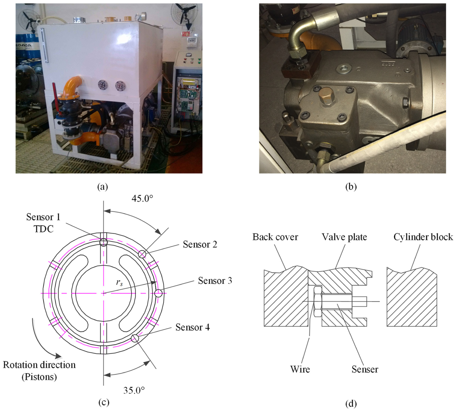
Experimental device: (a) the whole test rig, (b) test pump, (c) sensor position, and (d) schematic of sensor.
The test rig was designed and manufactured by Foshan Keda Hydraulic Machinery Co., Ltd in Foshan, Guangdong, China. Parameters of the tested pump can be found in Table 2. There were four eddy current sensors installed in the valve plate of the axial piston pump in the test rig, as illustrated in Figure 10(c), and one of them (Sensor 1) was installed near TDC. The range of the eddy current sensors was 100 µm with combined measure error of ±0.5%F.S. The sampling frequency was 10 kHz.
The film thickness during the starting period at TDC was measured and compared with the results calculated by the DST model. This test was repeated 10 times, hence there were 10 groups of data. The measured film thickness is also compared with the results calculated by the traditional fluid lubrication (FL) model. 18 For the first group of data, the comparison results are shown in Figure 11.
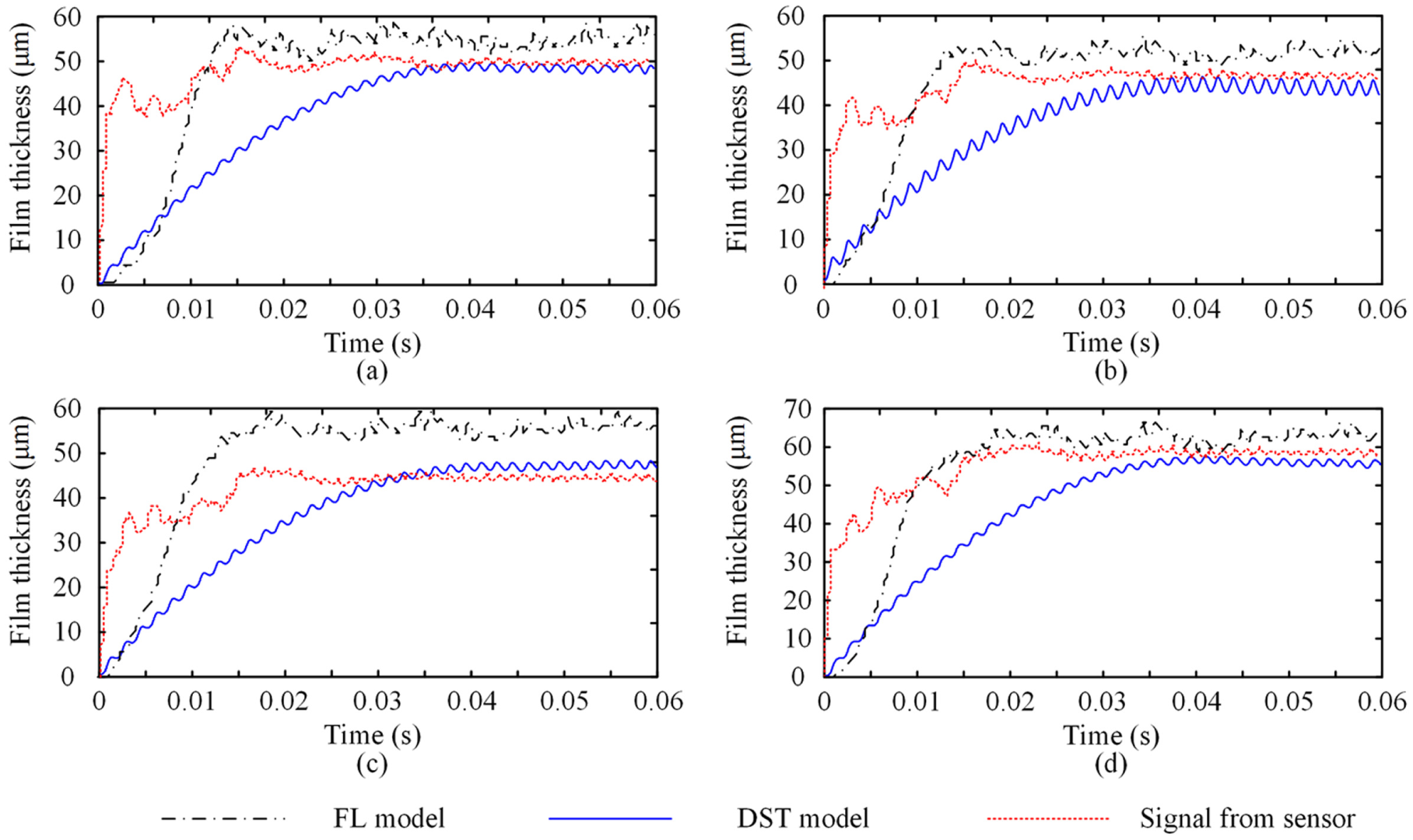
Comparison of film thickness at the position of (a) sensor 1 (TDC), (b) sensor 2, (c) sensor 3, and (d) sensor 4.
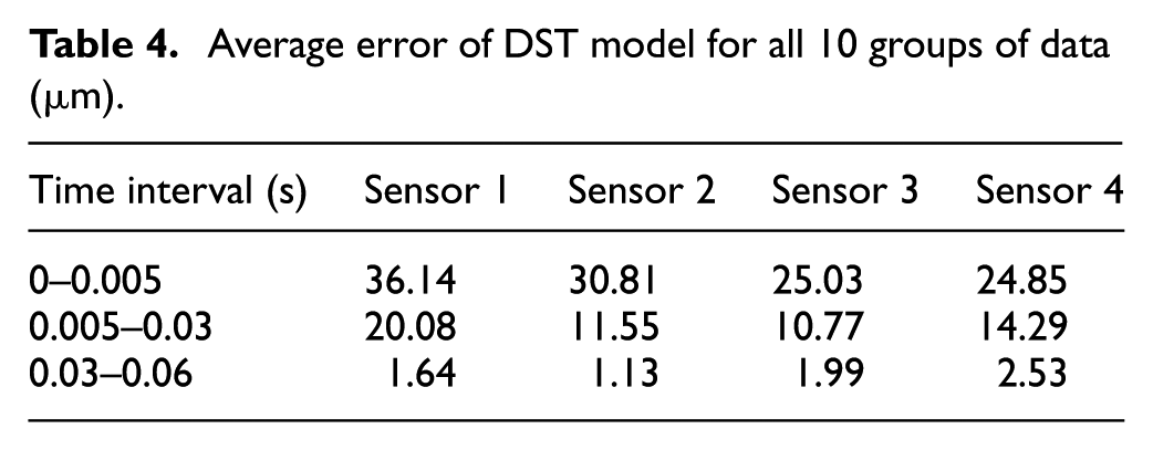
It can be seen in Figure 11 that at the beginning of the start process, for example, before 0.005 s, both DST model and FL model show large deviation. From 0.005 to 0.03 s, FL model tends to have less deviation from measured signal than DST model. However, after 0.03 s, DST model shows better agreement with the measured signal than FL model. The average error of DST model and FL model for all 10 groups of data in the three time intervals is shown in Tables 4 and 5, respectively.
Average error of DST model for all 10 groups of data (
Average error of FL model for all 10 groups of data (
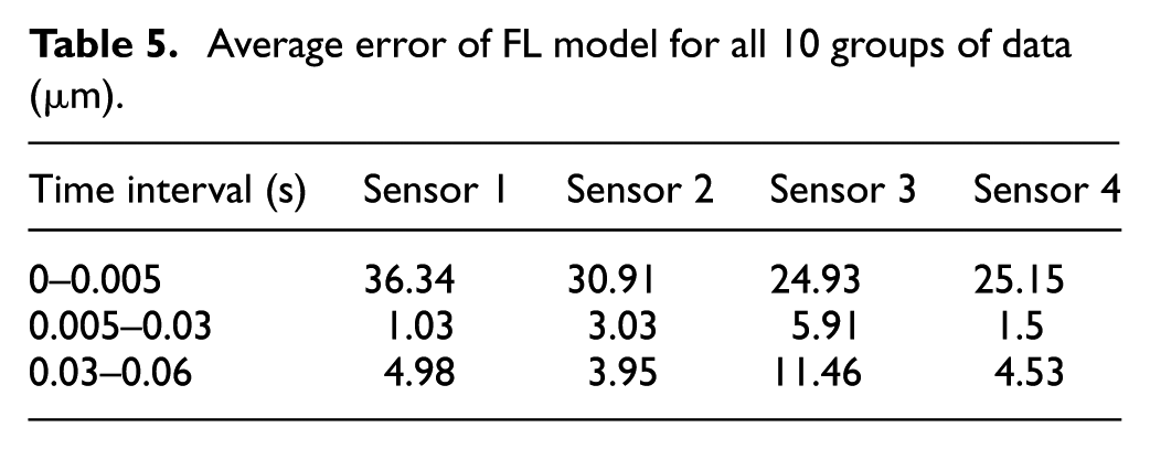
Based on the comparison between Tables 4 and 5, it can be concluded that after start period (after 0.03 s), the film thickness predicted by DST model has much less error than that of the FL model for all four sensors, which indicates that the DST model is more accurate after start period.
To further study the accuracy of DST model, we used a worn valve plate to replace the original valve plate in the pump and repeated the test for 10 times. Corresponding parameters for the simulation are listed in Table 6. In this case, the average error of DST model and FL model for all 10 groups of data in the three time intervals is shown in Tables 7 and 8, respectively. It can be concluded from Tables 7 and 8 that for the worn pump, error of both DST model and FL model is bigger than that when the pump was working normally. In addition, after start period (after 0.03 s), the film thickness predicted by DST model also has much less error than that of the FL model for all four sensors.
Parameters of the simulation for the worn pump.

Average error of DST model for all 10 groups of data for the worn pump (

Average error of FL model for all 10 groups of data for the worn pump (

Conclusion
In this article, a DST model is proposed to predict the film thickness between the valve plate and the cylinder block in axial piston pumps. This model divides the rotation of cylinder into seven stages and derives the complete analytical expression of the pressure distributions between valve plate and cylinder block. Then, the lubrication film forces and torques exerted on the cylinder block are calculated, and the dynamics of cylinder block are determined to calculate film thickness. Test results for both normal and worn pump show that the proposed DST model has better accuracy after start period in both cases. The DST model can be used to predict the oil film thickness between cylinder and valve plate in axial piston pumps in engineering applications and provide basic information of lubrication. Our future work should focus on the effects of swash plate angle, discharge pressure, and oil temperature on the film thickness distribution.
Footnotes
Appendix 1
Academic Editor: Yongming Liu
Declaration of conflicting interests
The author(s) declared no potential conflicts of interest with respect to the research, authorship, and/or publication of this article.
Funding
The author(s) disclosed receipt of the following financial support for the research, authorship, and/or publication of this article: This research is supported by the National Natural Science Foundation of China (grant nos 51505015 and 51305011) and the National Basic Research Program of China (973 Program, 2014CB046402).