
Abstract
This study developed a heat recovery air conditioner to supply on-demand air conditioning and reclaim waste heat during operation. In addition to the conventional refrigerant pipe, a plate heat exchanger was designed and connected in parallel to the condenser and evaporator. While refrigerant with high pressure and high temperature flows through the plate heat exchanger, the refrigerant flow is cooled down and condensed by cooling water from a water tank, and condensation heat in the exchanger is absorbed by the cooling water and stored in the water tank. In this study, solenoid valves were installed in the pipe to regulate the refrigerant volume in parallel connected pipes based on the tank water temperature by duty control logic. This multi-function heat recovery air conditioner has various operation modes. In summer, the air conditioner not only provides on-demand cooled air to air-conditioned rooms but also reclaims waste condensation heat through the plate heat exchanger. In winter, the air conditioner supplies on-demand heated air to indoor spaces and heats the water tank by simultaneously reclaiming waste condensation heat. According to an experimental operation test, the value of average water heating efficiency (COPh) of this air conditioner can reach 3.77 in the summer operating mode and 1.91 in the winter operating mode.
Keywords
Introduction
The literature has conducted a lot of innovative technologies and research studies to solve the energy consumption issues as with fossil energy still playing a major role as a source of fuel after the oil crises in the 1970s. 1 This has led researchers to conduct experiments related to energy-efficient solutions and seek out alternative energy sources that could replace fossil energy such as renewable energy systems. Some researchers have presented methodologies and results from overall energy system analysis of a 100% renewable energy system to review the feasibility of this type of system. 2 The US Department of Energy suggested two ways to reduce energy consumption from buildings. One way is to offset the rest of the energy usage through onsite renewable energy generation, and the other way is to reduce the average energy use of housing by 40%–100% through improving building energy systems’ efficiency and conservation. 3 Renewable energy incurs high costs of investment and is difficult to generate in large quantities, so there have been many other considerations to achieve this situation. The most appropriate way to solve problems of energy consumption currently is to reduce the use of fossil energy. China’s biggest amount of consumption comes from space-heating and air-conditioning systems, which are 20% of the total annual energy consumption. 4 In the United States, water heating accounts for 18% of all residential energy use, meaning it is the second largest user of energy in residential buildings. 5 It is forecasted that energy consumption of building space heating, air conditioning, and household sanitary water will continue to increase with economic growth. 6 Based on the statistics, the residential sector can help bring about a considerable amount of potential energy savings.7–9
Most of the residential buildings are equipped with conventional heaters generating heat by consuming fossil fuels or electricity, but a heat pump system as a heat-generating device can supply much more heat with the same amount of electric input used for a conventional heater. 10 The rejected (sensible and condensation) heat from air-conditioning systems is a readily available energy source that can be used to produce hot water. 11 Since the 1950s, research has looked into heat pump water heaters for energy savings, 12 with several studies addressing heat pump performance developed in the last two decades.13–21 However, the studies mainly focus on ways to save energy when supplying hot water. Conversely, a heat pump system can work with a variety of functions such as individual cooling, cooling and heat recovery, individual domestic hot water production, individual heating, and heating and domestic hot water production. 22 In other words, energy savings can be extracted with a well-integrated system of air conditioning and hot water supply.
Realizing the potential of air conditioners as a heat source for generating hot water, some studies have compared the performance of conventional heat pump systems with integrated air conditioning and hot water supply systems,23–25 and the results indicate that air-conditioning equipment contributes to a dramatic decline in energy costs and thermal pollution to the environment. Ji et al. 26 developed a prototype system and simulation program for a multi-function heat pump system. In their research, the hot water and heat exchanger (as the source of hot water) are connected in series, and the heat exchanger area of the hot water heater is not restricted. Thus, the system performance can be enhanced in the function of cooling and heat recovery, as well as when using individual domestic hot water production. Despite that, even the complicated program cannot achieve heating and production of domestic hot water simultaneously in winter with unused hot water.
Liu et al.12,27 proposed an improvement to the conventional multi-functional heat pump system, in which the system can operate in both heating and cooling modes. This proposed system can provide significant energy savings in space heating and hot water supply. In the heating mode, the system with air and water heat sources in parallel exhibits the best performance in both the space-heating mode and the space-heating plus hot water supply mode, compared to the system with other heat source combinations. However, there is no detailed analysis provided about the heat pump systems in parallel adjustment.
This article provides a detailed performance analysis about this adjustment, whereby the parallel arrangement in the multi-function heat pump systems can recover a greater amount of heat from the plate heat exchanger to the water. Because the refrigerant flow is adjusted by valves based on the water temperature, the system can generate hot water faster. At the same time, when the condenser and the plate heat exchanger are connected in a series adjustment, the system can only recover some portion of the condenser heat. Another issue that may arise is that the water temperature affects the supply air temperature from the indoor unit, but in this research, the temperature supply is kept steady when the parallel adjustment is applied.
Materials and methods
Overview of system principles of multi-function parallel heat recovery air conditioner
In this study, the parallel refrigerant pipe is used to recover the heat generated by a household air conditioner. A set of plate heat exchangers are installed parallel to the outdoor unit condenser, and a water pump circulates water to recover refrigerant condensation heat at the high-pressure side of the refrigerant pipe and store waste heat in a water tank. Figure 1 shows the system diagram of the refrigerant pipe in the new multi-function parallel heat recovery air conditioner. In this study, on and off periods of electromagnetic valves are used to regulate the refrigerant volume through an air-cooled condenser and plate heat exchanger based on load. In addition, a four-way refrigerant pipe valve from Saginomiya, Inc. in this study allows the system to simultaneously operate in summer and cooling mode. Because of the parallel refrigerant pipe design, while the system is producing hot water, the cooling or heating temperature in the air-conditioned space will not be affected by the thermal load in the water tank; in addition, the heat recovery efficiency of the refrigerant on the high-pressure side will be improved. Moreover, in the spring and summer seasons, the system can also produce only hot water. In addition, a special controller in the cooling and heating air conditioner system is replaced to facilitate the system test, as shown in Figure 2.
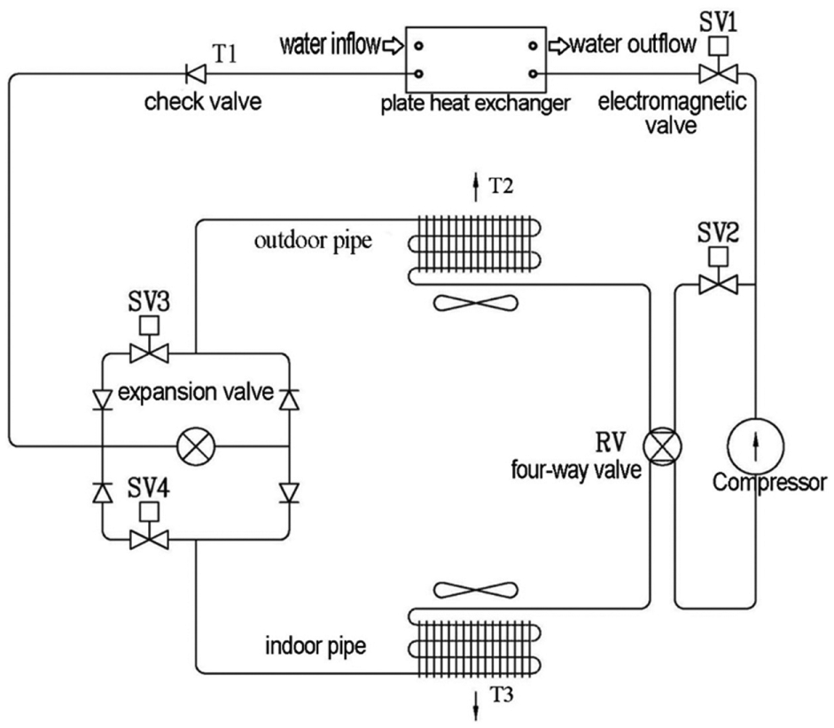
System diagram of refrigerant pipe in the new multi-function parallel heat recovery air conditioner.

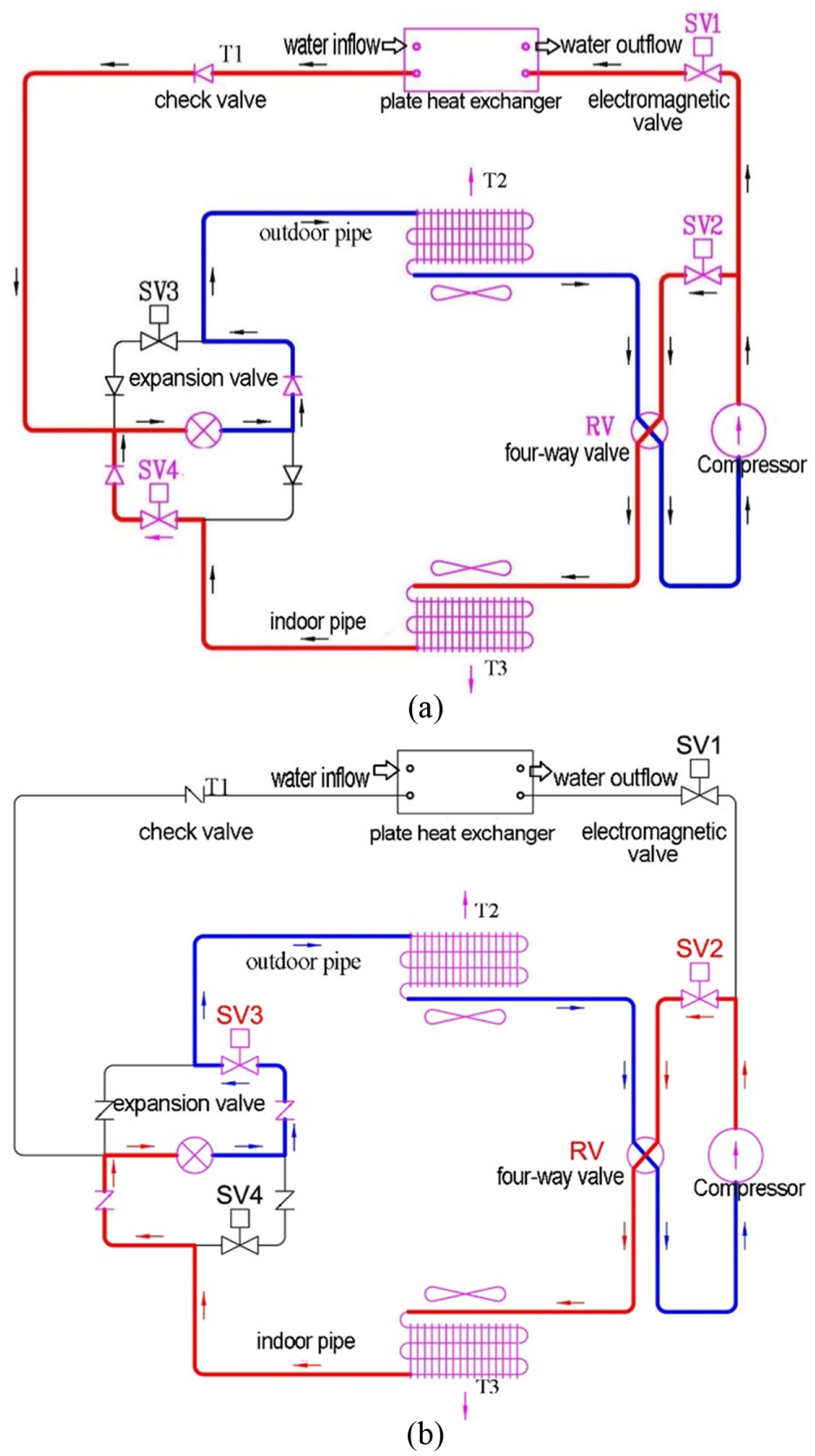
Refrigerant circulation diagram under the dedicated (a) cooling mode and (b) heating mode.
To achieve the goal of multiple functions and to maintain a reasonable system heat recovery efficiency, the refrigerant pipe design of the multi-function heat recovery air conditioner developed in this study is based on a parallel design mode, as shown in Figure 2. Electromagnetic valves are used to regulate the refrigerant volume through the plate heat exchanger and air-cooled condenser based on the hot water load variation. Compared to a series heat recovery mode, this parallel system can recover thermal energy more effectively and improve the water heating efficiency.
The refrigerant pipe used in this system is based on an expansion valve, electromagnetic valve, and check valve from Danfoss. The actions of these valves, such as the actions of the electromagnetic valve shown in Table 1, are used to drive the four-way valve and the electromagnetic valve between the parallel pipes to regulate the refrigerant flow direction. Therefore, this system can not only produce hot water while cooling an indoor space but also can heat water in the heating mode. The controller in this system is based on “Duty Control” control logic, and a proportional–integral–differential (PID) controller is used to control the on and off periods of the electromagnetic valve based on the hot water temperature variation sent from the temperature sensor. In other words, when the temperature sensor detects that the hot water tank temperature is relatively low, the refrigerant controller can reduce the refrigerant volume through the air-cooled condenser in the parallel refrigerant pipe to increase the refrigerant volume through the plate heat exchanger. When a relatively high water temperature is needed, an auxiliary electric heater is used for heating. When the temperature sensor installed in the hot water tank detects that the tank water temperature has reached a predefined hot water temperature, the refrigerant controller will activate the electromagnetic valve to limit the refrigerant volume through the plate heat exchanger and increase the refrigerant volume through the air-cooled condenser; simultaneously, the air-cooled condenser discharges waste heat to the atmosphere to maintain the operation efficiency of the air-conditioning equipment. In this study, the refrigerant pipe design based on a four-way valve, relevant electromagnetic valve, and check valve can achieve the following functions and characteristics:
In summer, the system can provide indoor cooling and simultaneously produce hot water and store it in a hot water tank.
In winter, the system can provide indoor heating and simultaneously produce hot water and store it in a hot water tank.
The parallel heat recovery mode can achieve high heat recovery efficiency and a rapid increase in hot water temperature. Even after a large volume of hot water is consumed and a large volume of cold water is replenished in the water tank, rapid heating can be achieved.
The heat recovery mode of the most multi-function air-conditioning products is based on a series tank heat exchanger and an outdoor unit, whose heating speed is relatively low. When a large volume of hot water is consumed and a large volume of cold water is replenished in the water tank, the water temperature increase will be slow.
Electromagnetic valve action table of multi-function air conditioner.
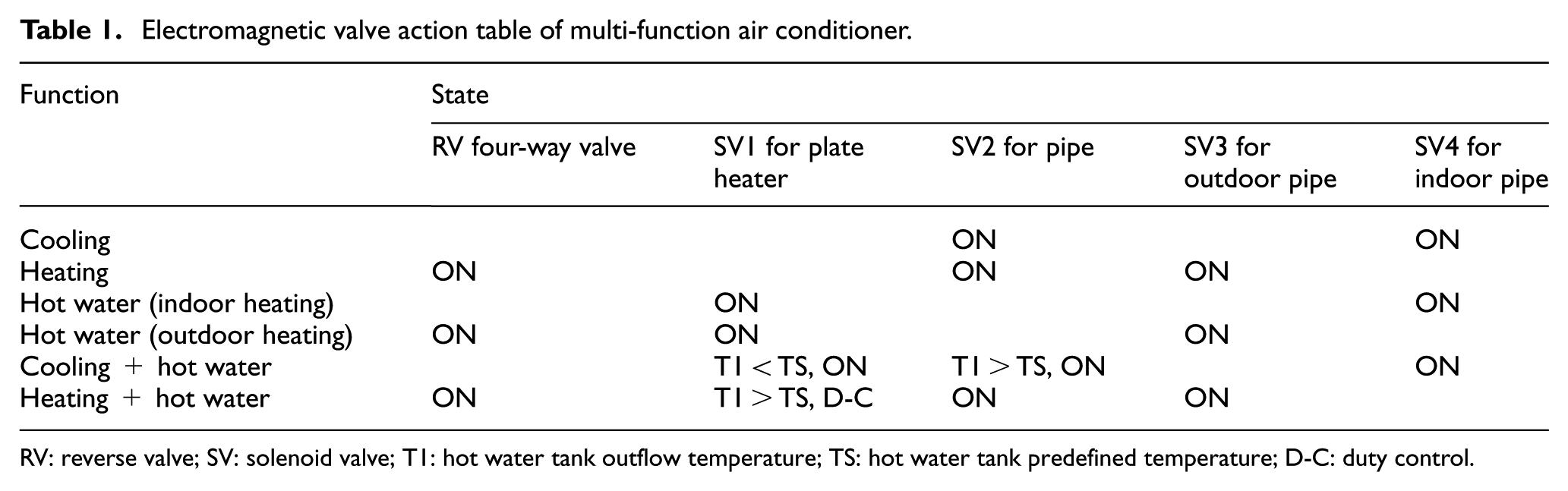
RV: reverse valve; SV: solenoid valve; T1: hot water tank outflow temperature; TS: hot water tank predefined temperature; D-C: duty control.
The equipment specifications of this system are as follows:
Water pump. Output: 0.18 kW, voltage: 220 V, rated capacity: 9 L/min.
Water tank. Rated capacity: 30 L.
Indoor unit. Capacity: 2.9 kW, energy consumption: 26 W, size: 800 × 295 × 230.
Outdoor unit. Capacity: 1.120 kW, power: AC 220 V 60 Hz, energy consumption: 967 W, refrigerant: R-22, size: 770 × 530 × 200.
Measurement equipment. Thermocouple type K: nickel–chromium or nickel–aluminum alloy, temperature range from −200°C to +1200°C, magnetic, sensitivity of 41 µV/°C, accuracy ± 2.2°C.
The sanitary water heating load,

where
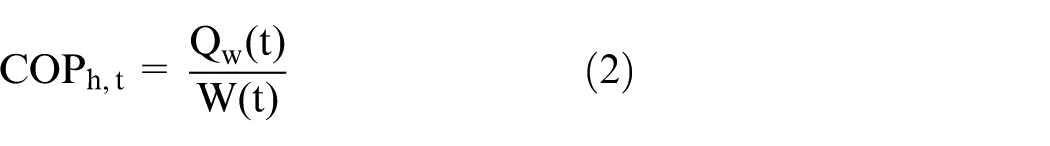
where

Dedicated cooling and heating mode of the multi-function air conditioner
Figure 2(a) shows the refrigerant circulation diagram under the dedicated cooling mode. Under the air-cooled cooling mode, high-temperature and high-pressure gaseous refrigerant flows into the outdoor heat exchanger via electromagnetic valve SV2 (solenoid valve); after heat exchange with the low-temperature outdoor air, gaseous refrigerant is condensed into liquid refrigerant, and heat is dissipated via outdoor air into the outdoor environment. Liquid refrigerant flows into the expansion valve via the check valve and undergoes throttle cooling. Then, electromagnetic valve SV4 imports refrigerant to the indoor heat exchanger. After heat exchange with the indoor air, the refrigerant is evaporated and turned into gaseous refrigerant; simultaneously, the refrigerant absorbs heat from the indoor air passing by, cools the indoor air and sends low-temperature air to the air-conditioned indoor environment. Evaporated liquid refrigerant is sent back to the compressor for the next circulation and to complete the cooling function, as shown in Figure 2(a).
Figure 2(b) and Table 1 show the refrigerant circulation diagram and the corresponding electromagnetic valve action under the dedicated heating mode. Under this operation mode, four-way valve SV and electromagnetic valves SV2 and SV3 are turned on. High-temperature and high-pressure gaseous refrigerant enters the indoor unit heat exchanger via electromagnetic valve SV2 and four-way valve RV (reverse valve); after heat exchange with the low-temperature indoor air, the gaseous refrigerant is condensed to liquid refrigerant, the indoor air is heated, and the high-temperature air is sent to the air-conditioned indoor environment. After heat dissipation, the refrigerant is imported by a check valve to the expansion valve and undergoes throttle cooling. Then, electromagnetic valve SV3 imports refrigerant to the outdoor unit heat exchanger. After heat exchange with the outdoor air, the refrigerant is evaporated and turned into gaseous refrigerant; simultaneously, the refrigerant absorbs heat from the outdoor air passing by, heats the outdoor air, and cools down. Then, low-temperature air is sent to the outdoor environment. After the gaseous refrigerant absorbs heat, it is sent back to the compressor for the next circulation and to complete the heating function, as shown in Figure 2(b).
Outdoor heat absorption and hot water production mode
Figure 3 and Table 1 show the refrigerant circulation diagram and the corresponding electromagnetic valve action under the outdoor heat absorption and hot water production mode. Under this operation mode, four-way valve SV and electromagnetic valves SV1 and SV3 are turned on. High-pressure gaseous refrigerant vapor from the compressor outlet enters the plate heat exchanger via electromagnetic valve SV1 and exchanges heat with the cold water from the water tank. After the condensed liquid refrigerant enters the expansion valve and undergoes throttle cooling, it is imported by electromagnetic valve SV3 to the outdoor heat exchanger to absorb the outdoor heat, and then, the produced cold air is sent outdoors. After the gaseous refrigerant absorbs heat, it is sent via four-way valve RV to the compressor for the next circulation and to complete the heat recovery hot water production function, as shown in Figure 3.

Refrigerant circulation diagram under the outdoor heat absorption and hot water production mode.
Control logic of hot water production and cooling multi-function operation
Table 1 and Figure 4(a) and (b) show the refrigerant circulation diagram and the corresponding electromagnetic valve action under the hot water production and cooling multi-function operation mode. As shown in Table 1, when the water temperature measurement of temperature sensor T1 at the water tank outlet is below a system predefined outflow temperature, electromagnetic valves SV1 and SV2 are turned off. As shown in Figure 4(a), under this operation mode, the water pump sends water in the water tank to the plate heat exchanger to exchange heat with refrigerant and then returns it to the water tank. Temperature sensor T1 at the water tank outlet can send water tank outflow temperature information back to the PID controller in real-time for calculation and analysis. When the water tank outflow temperature is below the predefined water tank temperature TS, electromagnetic valve SV2 is turned off and electromagnetic valve SV1 is turned on. High-pressure gaseous refrigerant from the compressor outlet flows into the plate heat exchanger, exchanges heat with the cold water from the water tank, and is then condensed into liquid refrigerant. Next, after expansion valve expansion cooling, the refrigerant is sent via electromagnetic valve SV4 to the indoor heat exchanger, evaporates under low pressure, absorbs thermal energy, and cools the indoor air. Then, gaseous refrigerant is sent to the compressor for the next circulation and to complete the parallel multi-function operation of hot water production and cooling.

Refrigerant circulation diagram under the hot water production and cooling multi-function operation mode: (a) T1 < TS and (b) T1 > TS.
As shown in Table 1, when the temperature sensor T1 detects that the water tank outflow temperature has reached a predefined temperature TS, the electromagnetic valve SV2 is turned on, and the temperature sensor T1 sends a signal back to the PID controller for calculation and analysis. Electromagnetic valves SV1 and SV2 are used to control the refrigerant volume through the plate heat exchanger pipe and outdoor heat exchanger parallel pipe. High-pressure gaseous refrigerant from the compressor outlet flows via a three-way valve into the plate heat exchanger and outdoor heat exchanger. The on and off periods of electromagnetic valves SV1 and SV2 and the water tank outflow temperature can be used to control the refrigerant volume through the plate heat exchanger and outdoor heat exchanger. Therefore, water tank overheating is prevented and constant temperature hot water production is achieved. During this process, the indoor cooling will not be affected. The refrigerant circulation is shown in Figure 4(b).
Control logic of hot water production and heating multi-function operation
Table 1, Figure 5(a) and (b) show the refrigerant circulation diagram and corresponding electromagnetic valve action under the hot water production and heating multi-function operation mode. As shown in Figure 5(a), the four-way valve parallel to the compressor can switch the refrigerant circulation to heating mode. When the water tank outflow temperature is below the predefined water tank temperature TS, temperature sensor T1 sends a signal back to the PID controller for calculation and analysis. Next, the on and off periods of electromagnetic valves SV1 and SV2 are used to control the refrigerant volume through the plate heat exchanger pipe and indoor heat exchanger parallel pipe. Therefore, the plate heat exchanger reclaims heat and water tank overheating is prevented. Constant temperature hot water is produced while heat is dissipated to the indoor space via the indoor heat exchanger to maintain indoor heating.
Refrigerant circulation diagram under the hot water production and heating multi-function operation mode: (a) T1 < TS and (b) T1 > TS.
When temperature sensor T1 detects that the water tank outflow temperature has reached a predefined temperature TS, electromagnetic valve SV1 is turned off and electromagnetic valve SV2 is turned on. High-pressure gaseous refrigerant from the compressor outlet flows into the indoor heat exchanger, undergoes expansion valve expansion, exchanges heat via the outdoor heat exchanger, and flows back to the compressor. This is the dedicated heating refrigerant circulation mode, as shown in Figure 5(b).
Results and discussions
Performance of the space cooling mode of the air-conditioning/heat pump system
Figure 6 shows the indoor unit and outdoor unit outlet air temperature distribution for the heat pump air conditioner operating at a room temperature of 26°C. At the initial operation stage, the temperatures measured by temperature sensors T2 and T3 at the outdoor unit and indoor unit outlets are both 26°C. After approximately 5 min of system operation, the outdoor unit outlet temperature is maintained at approximately 35°C ± 1°C, and the indoor unit outlet temperature is maintained at approximately 10°C ± 1°C. This operation test can measure the heat dissipation and cooling performance of this heat pump air conditioner in pure air-to-air operation at an environmental temperature of 26°C. The subsequent test will use this operation performance as the basis for comparison and investigation.

Indoor unit and outdoor unit supply air temperature distributions for the AC/HP heat pump air conditioner operating at an environmental temperature of 26°C.
Performance analysis for multi-function operation of hot water production and cooling
Figure 7 shows the indoor unit and outdoor unit outlet air temperatures and water tank outflow temperature distribution curve for the air-conditioning/heat pump (AC/HP) system under the multi-function operation mode of hot water production and cooling. At the initial stage of system operation, the water tank outflow initial temperature is approximately 22.7°C. After system operation starts, temperature sensors T1, T2, and T3 are used to measure the hot water tank outflow temperature and the temperatures at the outdoor unit and indoor unit outlets. The diagram shows the temperature distribution curve under system operation, and the water tank outflow temperature distribution curve is at the top. Because the water tank outflow temperature at the initial operation stage is 22.7°C, which is below the system predefined hot water tank water storage temperature of 45°C (TS), after system operation starts, most of the high-pressure gaseous refrigerant from the compressor outlet flows through the plate heat exchanger and exchanges heat with the cold water from the water tank. Therefore, after the heated hot water flows back to the storage tank, the temperature of the water in the tank rises, and the water tank outflow temperature also increases with the operation time. In the case of the outdoor unit air-cooled heat exchanger, because only a low volume of high-pressure gaseous refrigerant flows in, the temperature of air flowing through the outdoor air-cooled heat exchanger is maintained at an approximately constant level. After 13.75 min of system operation, the water tank outflow temperature has reached the predefined temperature of 45°C. At this moment, the T1 sensor sends the temperature measurement to the PID controller for calculation and analysis. Electromagnetic valves SV1 and SV2 are used to control the refrigerant volume through the plate heat exchanger pipe and the outdoor heat exchanger parallel pipe. The on and off periods of electromagnetic valves SV1 and SV2 are used to control the water tank outflow temperature, prevent water tank overheating, and maintain a stable indoor unit air supply temperature. The diagram shows that after the water tank outflow temperature has reached 45°C, refrigerant diversion can maintain the water tank outflow temperature in the range of 45°C ± 1°C. During this period, because a relatively large proportion of high-pressure gaseous refrigerant flows through the indoor heat exchanger, the indoor unit outlet temperature suddenly increases to approximately 45°C. However, because this controller uses on and off periods of electromagnetic valves SV1 and SV2 to control the refrigerant volume through the plate heat exchanger and the indoor heat exchanger, respectively, the indoor unit outlet temperature distribution fluctuates during this period. In addition, because the high-pressure side gaseous refrigerant has a stable flow distribution, regardless of whether the water tank outflow temperature is below or above the predefined temperature, the indoor unit heat exchange outlet temperature is always maintained at a stable level of 10°C. In other words, the indoor unit air supply temperature of this system will not be affected by the water tank temperature and high-pressure side gaseous refrigerant diversion control.

Supply air temperature distribution of indoor unit, outdoor unit, and outflow temperature of water tank.
Table 2 shows the corresponding system heating capacity and average heating COPh data at different water tank outflow temperatures for the AC/HP system under the hot water production and cooling multi-function operation mode. The table shows that when the water tank outflow temperature is relatively low, the high-pressure side refrigerant has relatively low pressure; therefore, the compressor also consumes a relatively low level of electric current and electric power. However, at this moment, the water tank outflow temperature is relatively low and the high-pressure side refrigerant condensation heat can easily be carried away by circulating water. Therefore, the system momentary heating capacity is also relatively high. When the water tank outflow temperature is at 25°C, the average system COPh can reach 4.766. With the gradual rise in water tank outflow temperature, the compressor also consumes an increasing level of electric current and electric power. However, at this moment, because the water tank outflow temperature increases, it is more difficult for the high-pressure side refrigerant condensation heat to be carried away by circulating water; therefore, the system momentary heating capacity also gradually decreases. After 825 s of heating, the water tank outflow temperature reaches 45°C and the system average COPh at that moment drops to 3.122.
Heating capacity and average COPh at different water tank outflow temperature under the hot water production and cooling mode size.

1 W = 0.0009478 Btu/s; COP = 1.163 EER.
Operation mode of outdoor heat absorption and hot water production
Figure 8 shows the indoor unit outlet air temperature and water tank outflow temperature distribution curve of the AC/HP system under the hot water production and cooling operation mode. This system operates at an environmental temperature of 26°C. At the initial stage of system operation, the water tank outflow initial temperature is approximately 23°C. After approximately 15 min of system operation, the hot water temperature can reach a predefined temperature of 45°C; after 44 min of operation, the hot water temperature can reach as high as 80°C. However, because the hot water temperature is 55°C, the pressure at the high-pressure side of the gaseous refrigerant from the compressor outlet is already 24 kg/cm2 (gauge pressure). To ensure long-term operation of the machine, the hot water temperature is set to 45°C. Because this temperature is higher than comfortable bathing temperature, there is no need to further increase this number. Future applications in larger equipment may set this value differently according to the application requirements.

Supply air temperature distribution of indoor unit and outflow temperature of water tank under the hot water production and cooling operation mode.
Performance analysis for different hot water supply loads under the hot water production and cooling operation mode
Figure 9 shows the water tank outflow temperature distribution curve of the AC/HP system with different hot water supply loads under the hot water production and cooling operation mode. After the water tank hot water temperature has reached 45°C, it is assumed that normal bathing takes 10 min. During these 10 min, a certain volume of hot water is supplied and an identical volume of 22.7°C cold water is replenished. Simultaneously, the system maintains its operation. The outflow temperature variation curve is obtained via a temperature sensor at the water tank outlet. The diagram shows that when the water tank outflow is above 4.5 L/min, the water tank outflow temperature gradually decreases over time. After 10 min of system operation, the water tank outflow temperature is below 30°C.

Temperature water tank outflow distribution of AC/HP systems with different hot water supply loads under the hot water production and cooling operation mode.
When not used in tandem with a water heater, the hot water outflow for 10 min of bathing can only be maintained at 3 L/min; at 2.57 L/min, the temperature drop curve is the gentlest. However, heat recovery aims to warm up water, offload the large amount of energy consumed by an electric water heater to heat water from room temperature to the intended range, and reduce the heating period of an electric water heater.
Performance analysis for multi-function operation of hot water production and heating
Figure 10 shows the operation curve of an AC/HP under heating mode when the AC/HP operates at a room temperature of 23.7°C. The heating system stabilizes within 5 min of operation. In the diagram, the curve at the top shows that the indoor unit outlet temperature is maintained at a constant level of 50°C ± 1°C, which reflects the heating performance of the original air conditioner. Subsequent tests use this diagram as the basis for comparison and investigation.

AC/HP operation systems under heating mode at room temperature of 23.7°C.
Figure 11 shows the indoor unit and outdoor unit outlet air temperatures and water tank outflow temperature distribution curve of the AC/HP system under the hot water production and heating multi-function operation mode. This system operates under an outdoor environment temperature of 26°C. At the initial stage of system operation, the water tank outflow initial temperature is approximately 22.7°C. After system operation starts, temperature sensors T1, T2, and T3 are used to measure the hot water tank outflow temperature and the temperatures at the outdoor unit and indoor unit outlets. Because the water tank outflow temperature at the initial operation stage is 22.7°C, which is below the system predefined hot water tank water storage temperature of 45°C (TS), after system operation starts, part of the high-pressure gaseous refrigerant from the compressor outlet flows through the plate heat exchanger and exchanges heat with the cold water from the water tank. Therefore, the heated hot water flows back to the storage tank, the water temperature in the tank rises, and the water tank outflow temperature also increases with operation time. Because only part of the high-pressure gaseous refrigerant flows in, the temperature of the indoor air back from the heat exchanger increases to 35°C after 1 min of system operation. After that, with the increase in the water tank outflow temperature, the temperature of the refrigerant flowing into the indoor unit heat exchanger increases proportionally. Furthermore, the air temperature from the indoor unit gradually increases with increasing refrigerant volume. After 33 min of system operation, because the water tank outflow temperature has reached the predefined temperature of 45°C, the T1 sensor sends temperature information to the PID controller for calculation and analysis. Then, electromagnetic valves SV1 and SV2 are used to control the refrigerant volume through the plate heat exchanger pipe and outdoor heat exchanger parallel pipe. High-pressure gaseous refrigerant from the compressor outlet flows into the plate heat exchanger and outdoor heat exchanger via a three-way valve. The on and off periods of electromagnetic valves SV1 and SV2 and the water tank outflow temperature are used to control the refrigerant volume through the plate heat exchanger and outdoor heat exchanger, to prevent the water tank from overheating and to maintain a stable indoor unit air supply temperature. The diagram shows that after the system refrigerant is diverted, the water tank outflow temperature can be maintained at 45°C ± 1°C. Because a relatively large proportion of high-pressure gaseous refrigerant flows through the outdoor air-cooled heat exchanger, the outdoor unit outlet temperature increases to approximately 28°C. However, because this controller uses on and off periods of electromagnetic valves SV1 and SV2 to control the refrigerant volume through the plate heat exchanger and air-cooled heat exchanger, the outdoor unit outlet temperature distribution fluctuates during this period. In addition, because the high-pressure side gaseous refrigerant has a stable flow distribution, regardless of whether the water tank outflow temperature is below or above the predefined temperature, the outdoor unit heat exchanger outlet temperature always stabilizes at 22°C. In other words, the indoor unit air supply temperature of this system will not be affected by the water tank water temperature or the high-pressure side gaseous refrigerant diversion control. Under the hot water production and cooling operation mode, it takes approximately 35.67 min for the water tank outflow temperature to increase from 22.7°C to 45°C. However, under the hot water production and heating operation mode, because the heat acquired from the outdoor unit air heat source is supplied simultaneously to heating the circulating water in the water tank and indoor heating, it takes approximately 33 min for the water tank outflow temperature to increase from 22.7°C to 45°C.

Temperature distribution of indoor, outdoor unit outlet air temperatures and water tank outflow temperature when the AC/HP system under the hot water production and heating multi-function operation mode.
Table 3 shows the corresponding system heating capacity and average heating COPh data at different water tank outflow temperatures for the AC/HP system under the hot water production and heating multi-function operation mode. The table shows that when the water tank outflow temperature is relatively low, the high-pressure side refrigerant has relatively low pressure and the compressor consumes a relatively low level of electric power. At this moment, because the water tank outflow temperature is relatively low, the high-pressure side refrigerant condensation heat can be easily carried away by the circulating water, and the system momentary heating capacity is relatively high. When the water tank outflow temperature is 25°C, the system average COPh can reach 3.461. Compared to the system under the hot water production and cooling multi-function operation mode in Table 2, in the hot water production and heating operation mode, the heat acquired from the outdoor unit air heat source is simultaneously supplied to heat the circulating water in the water tank and indoor heating; therefore, the water heating capacity by comparison is relatively low. Similarly, with the gradual increase in the water tank outflow temperature, the compressor consumes an increasing level of electric current and electric power; the system momentary heating capacity decreases gradually. After 35.67 min of heating, the water tank outflow temperature reaches 45°C, and the system average COPh at that moment drops to 1.208.
System heating capacity and average heating COPh data at different water tank outflow temperatures.

1 W = 0.0009478 Btu/s, COP = 1.163 EER.
Performance analysis of various hot water supply loads under the hot water production and heating multi-function operation mode
Figure 12 shows water tank outflow temperature distribution curves of various hot water supply loads for the AC/HP system under the hot water production and heating operation mode. After the water tank hot water temperature has reached 45°C, a constant supply of hot water is provided in 10 min and an identical flow of 22.7°C cold water is replenished; simultaneously, the system maintains its operation, and the outflow temperature variation curve is obtained from the temperature sensor at the water tank outlet. The diagram shows that when the water tank outflow is above 6 L/min, the water tank outflow temperature gradually decreases over time. After 10 min of system operation, the water tank outflow temperature is below 30°C.

Temperature distribution of various hot water supply loads for the AC/HP system under the hot water production and heating operation mode.
When not used in tandem with a water heater, the hot water outflow for 10 min of bathing can only be maintained at 3 L/min, and the water tank outflow temperature can be maintained above 40°C; at 2.3 L/min, the temperature decrease curve is the gentlest. Under the heating mode, because half of the heat is supplied to the indoor outlet, the cooling of each flow is accelerated. However, heat recovery warms up the water, offloads the large amount of energy consumed by an electric water heater to heat water from room temperature to the intended range, and reduces the heating period of an electric water heater.
Table 4 shows the corresponding system heating capacity and average heating COPh data at different water tank outflow temperatures when the water stored in the water tank is electrically heated from 22.7°C to 60°C. The table shows that, regardless of the water temperature in the water tank, the electric current, electric power, and heating capacity are all fairly stable, while the system average operation COPh only slightly decreases. Compared to the operation modes in Tables 2 and 3, under the hot water production and cooling or heating operation mode, in the temperature range of hot water for domestic use, this system has higher operation efficiency than the conventional electric heating method.
System heating capacity and average heating COPh data at different water tank outflow temperatures when the water stored in the water tank is electrically heated from 22.7°C to 60°C.
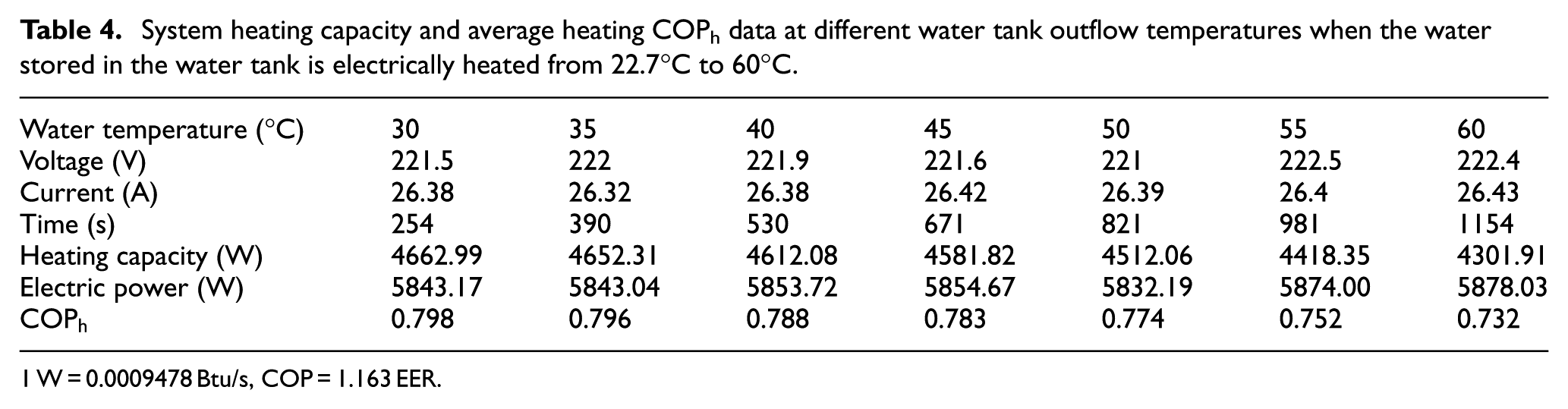
1 W = 0.0009478 Btu/s, COP = 1.163 EER.
Conclusion
In this study, a multi-function AC/HP air conditioner is developed based on a parallel refrigerant pipe design and a duty control refrigerant flow control method. The parallel refrigerant pipe design can improve the condensation heat recovery efficiency of the high-pressure side refrigerant. When the water tank outlet temperature is set to 45°C, tests show that this system can complete water heating within 15 min, which reduces both water heater power consumption and the heating period. The refrigerant flow is regulated according to the load so that when the system is simultaneously providing hot water, cooling and heating, the cooling and heating temperatures, and the system operational performance will not be affected by variations in the water tank outlet temperature, and the air temperature can be maintained at a stable level.
Footnotes
Appendix 1
Academic Editor: Stephen D Prior
Declaration of conflicting interests
The author(s) declared no potential conflicts of interest with respect to the research, authorship, and/or publication of this article.
Funding
The author(s) disclosed receipt of the following financial support for the research, authorship, and/or publication of this article: This study was financially supported by the Ministry of Science and Technology of Taiwan under grant Nos. MOST 103-2622-E-167-019-CC3 and MOST 104-2221-E-167-026-MY2.