
Abstract
In this study, the tangential magnetic field Nd-Fe-B permanent magnet generator is designed and analyzed. In the generator, the adjacent permanent steel is sequentially arranged on the radial groove by the way of same polarity-oriented manner. The optimal design parameters of the generator are obtained by analyzing the influence rule of the generator leakage magnetic flux and leakage coefficient which is affected by the change in rotor pole pairs, permanent steel thickness, magnetic isolation air width, and air-gap length. The mathematical model of the magnetic field is developed and analyzed using the finite element method. Using the finite element method model, the diagrams of magnetic force line distribution, magnetic flux density modulus value, and magnetic flux density vector are obtained, which can be used to verify the validity of the main design parameters. A three-phase half-wave impulse-type controlled rectifier voltage regulator is developed with the function of regulator and rectifier, which proposes a solution to the output voltage instability of the Nd-Fe-B permanent magnet generator in a wide speed and load range.
Keywords
Introduction
At present, the magnetic field of brushless silicon rectifier generator is generated by an electrical excitation winding (EEW). However, only part of the electricity energy is transmitted to the EEW while most of the energy is wasted in the way of excitation winding generating heat. The EEW of the rotor can be burnt and disconnected easily and requires the battery excitation current. In addition, due to the increase in the magnetic field air-gap in the generator, it has some disadvantages such as large magnetic flux leakage, low material utilization efficiency, and high cost.1–3 So silicon rectifier generator has been gradually replaced by permanent magnet generator (PMG) and hybrid excitation generator, and many experts and scholars have carried out deep research on all kinds of generators.
Xia et al. 4 proposed a novel hybrid excitation permanent magnet (PM) synchronous generator utilizing tooth harmonic for excitation, derived the mathematical model of the machine system represented by circuit, and analyzed the operation mode of rectifier circuit in the tooth harmonic excitation system. Zhu et al. 5 proposed a novel integrated brushless excitation method which is applied to a rotor-excited hybrid excitation synchronous generator to realize brushless excitation for a rotor-excited generator. Chen et al. 6 proposed a general nonlinear mathematical model of PM synchronous motor considering saturation, magnetic field spatial harmonics, and time harmonics, based on the classical Park’s transformation theory and the Fourier series analysis of the magnetic field. Ayaz et al. developed a new PM alternator, which has a main alternator winding and an auxiliary winding. The auxiliary winding is connected to a 300 V direct current (DC) bus through a DC/alternating current (AC) inverter which enables full control over the winding current. 7
Based on the above literature review, we can see that most researchers research on the different efficiency generator’s structure and new mathematical simulation model, and only a small part of researchers involve in the generator voltage regulator. But the controller is one of the most important key technologies of the generator, and its operation quality and control precision can determine the application and promotion of the generator.8–11 So this article developed a power generating device which has a PMG and a controlled rectifier voltage regulator, and in comparison with the existing studies, this work has four contributions: (1) a tangential magnetic field Nd-Fe-B PMG is designed, which has less power consumption, higher power generation efficiency, lower failure rate, steady output voltage, and significant effect of assembling magnet; (2) magnetic flux leakage analysis and magnetic finite element analysis are done to optimize the structure design; (3) three-phase half-wave impulse-type controlled rectifier voltage regulator is designed and analyzed in detail to stabilize the output voltage; and (4) the prototype has been produced and the generator test has been performed with various rotary speeds and load power.
The rest of this article is organized as follows: section “Main structure parameters of generator” designs and calculates the main parameters of the generator. Section “Magnetic flux leakage analysis and magnetic finite element analysis of generator” analyzes the magnetic flux leakage and magnetic field using the finite element method (FEM). Section “Three-phase half-wave impulse-type controlled rectifier voltage regulator principle” describes and analyzes the designed controlled rectifier voltage regulator. Section “Performance test” verifies the output performance of the designed generator. Finally, section “Conclusion” concludes our work.
Main structure parameters of generator
The tangential magnetic Nd-Fe-B PMG is combined by the PM rotor, stator, front cover, rear cover, and voltage regulator. The structure is shown in Figure 1.

Structure diagram of tangential magnetic rare earth PMG.
Permanent steel volume
The low-speed output characteristic parameters of Nd-Fe-B PMG are mainly related to the remanent flux density, coercive force, and maximum energy product. 12 Since the automotive generator is developed with the trend of lightweight and miniaturization, the permanent steel should be designed with thinner thickness, higher remanent magnetic flux density, coercive force, and maximum energy product.13–15 Based on the requirements of the magnetic properties, the Nd-Fe-B permanent steel is selected in this design.
The permanent steel volume is calculated using short-circuit triangle method 16

where PN is the apparent power when power factor cos ϕ is 0. σ0 is the leakage coefficient; if it has pole shoe star rotor, then σ0 = 1.2–1.5. Kad is the conversion factor of direct axis armature reaction magnetic potential;
Armature winding turns
Based on the principle of electromagnetism, armature winding turns of each phase generator is calculated 17

where Kw is the winding coefficient of the armature winding;
Rotor
The rotor outer diameter is calculated using the following equation

where Km is the filling factor of the PM steel;
Stator size
In order to calculate the permeance of the generator stator tooth portion, yoke, and the leakage permeance between the stator tooth, it is necessary to draw groove figure of stator punching. The groove figure of stator punching is pear-shaped groove and is shown in Figure 2.

Stator punching and pear-shaped slot.
1. Stator core inner diameter D1

The excitation of the magnetic potential size and the saturation degree of no-load characteristics are affected by the air-gap δ between the rotor and the stator. It is favorable to the linear extent of the no-load characteristics if there is a small δ value. However, if the value of δ is too small, it may cause friction problem between the generator stator and the rotor. With the increase in the value of δ, the excitation magnetic potential as well as the volume of the portion in the electrical excitation increases.18–20
2. Stator slot width bs0
For the stator slot width, it is necessary to select a relatively small value, which should ensure easy machining and convenient embedding.
3. Stator tooth width bt

where Lef is the axial calculation length of air-gap, Lef = LS; t is the stator pole pitch,
4. The stator yoke height has

where Bas is the stator yoke flux density.
In order to prevent short circuit, it is necessary to set a certain gap between the armature winding terminal portion and the generator cover.
5. The stator slot area As

where bs1 is the stator slot width of small tip,
6. The diameter of the armature winding wire ds
The cross-sectional area of armature winding wire is calculated as follows
where IN is the rated phase current,
Wire diameter
Magnetic flux leakage analysis and magnetic finite element analysis of generator
The developed tangential PM synchronous generator has three phases, eight poles, and 36 slots.21,22 The cross-sectional view of the rotor is shown in Figure 3.

Tangential PMG cross-sectional view.
Influence of the pole pairs’ number on the magnetic flux leakage
The leakage magnetic flux of the generator is analyzed with the pole pair numbers of 2, 3, 4, 5, and 6 while the remaining structural parameters of the tangential PMG are not changed. The simulation results are shown in Figures 4 and 5.
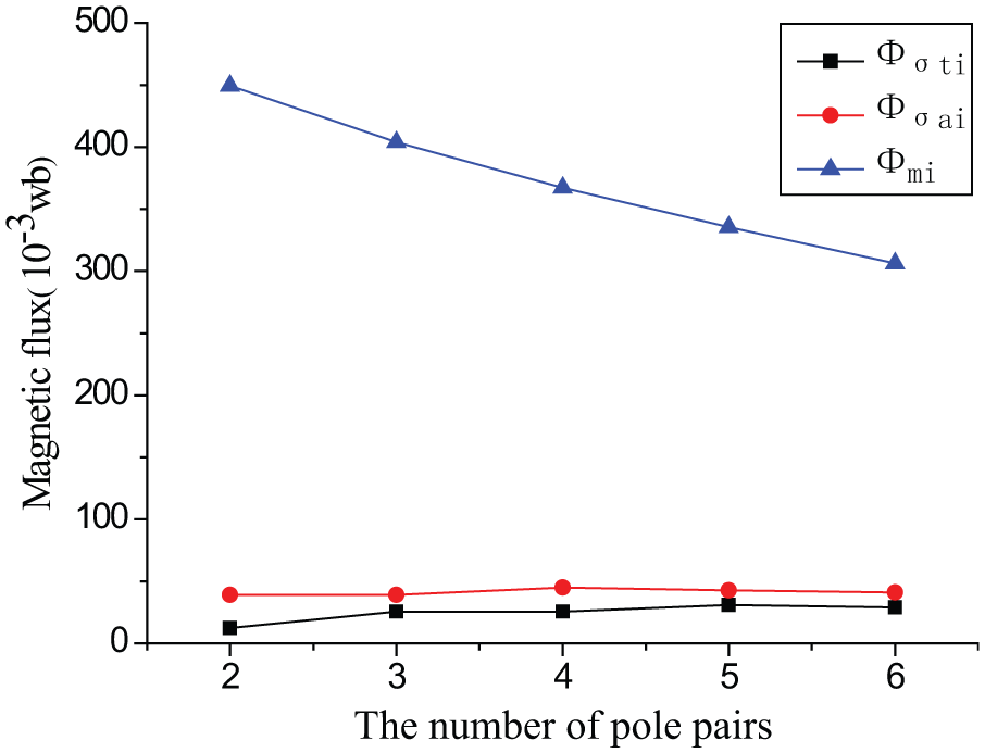
Magnetic flux via the number of pole pairs.

Magnetic flux leakage coefficient via the number of pole pairs.
In Figure 4, Φmi is the flux that is provided by a single PM for outward magnetic circuit. Φσti is the leakage flux of the tooth top. Φσai is the leakage flux of the shaft portion. In Figure 5, σ is the magnetic flux leakage coefficient.
It is known that if the pole pair number is increased, the flux density can be improved, which reduces the volume and mass of the generator and improves the generator efficiency. However, it is seen from Figures 4 and 5 that with the increase in the pole pair number, Φmi is decreased, Φσti is increased, Φσai has no apparent change, and σ is increased gradually which reduces the utilization efficiency of the PM steel. Therefore, it is necessary to consider the overall performance of the generator as well as the use degree of the permanent steel magnetic during the selection of the generator pole number. In this design, p = 4.
Influence of the permanent steel thickness on the magnetic flux leakage
The generator magnetic flux leakage is analyzed when the thickness of the PM is 2, 3, 4, 5, and 6 mm. The simulation results are shown in Figures 6 and 7.
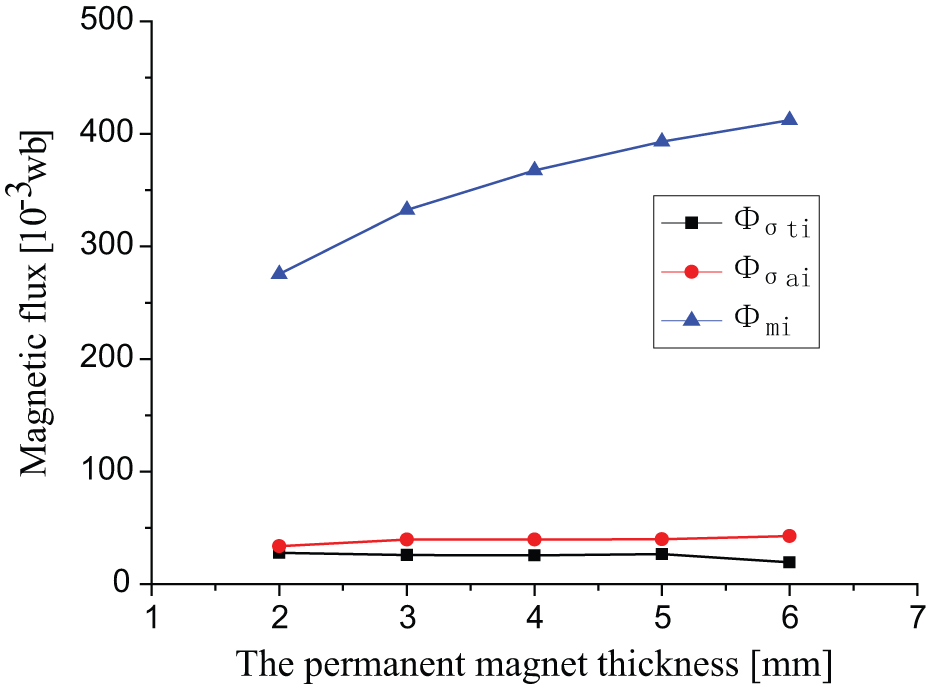
Magnetic flux via the permanent magnet thickness.

Magnetic flux leakage coefficient via the permanent magnet thickness.
It is seen from Figure 6 that Φmi is increased with the increase in PM thickness while there is no apparent change in the magnetic flux leakage section. Therefore, the air-gap flux of the generator has a positive linear relationship with the PM thickness, which improves the generator capacity. Since the main magnetic flux of the magnetic circuit cannot be increased limitlessly due to the rotor material, the permeability capacity of the stator teeth, and the stator yoke, the magnetic flux increment of the single permanent steel for outward magnetic circuit becomes smaller.23,24
As shown in Figure 7, σ is reduced with the increase in PM thickness, which is favorable to improve the use degree of the permanent steel magnetic and overall performance of the generator. However, the generator cost will increase with the increase of the thickness of the PM steel. Therefore, appropriate permanent thickness should be selected. In this design, the thickness of the PM steel is designed as 4 mm.
Influence of the magnetic isolation air width on the magnetic flux leakage
The generator performances of the Φmi, Φσti, and Φσai are investigated with the change in the magnetic isolation air width (1–10 mm) while the remaining structural parameters of the tangential PMG are not changed. 25 The simulation results are shown in Figures 8 and 9.
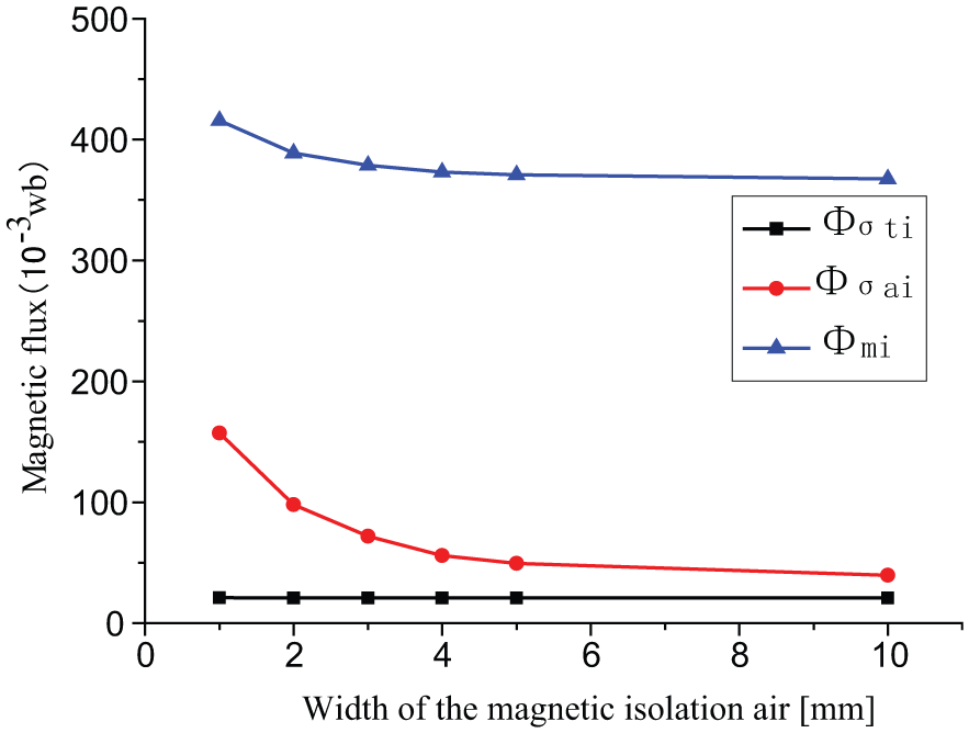
Magnetic flux via the magnetic isolation air width.

Magnetic flux leakage coefficient via the magnetic isolation air width.
As shown in Figures 8 and 9, it is found that Φσai has apparent decrease, and σ is reduced correspondingly with the change in the magnetic isolation air width from 1 to 5 mm. However, Φmi, Φσti, Φσai, and σ have no apparent changes while the magnetic isolation air width changes from 5 to 10 mm. Therefore, the width of the magnetic isolation air should be designed appropriately. In this design, the width of the magnetic isolation air is 4 mm.
Influence of the air-gap length on the magnetic flux leakage
The generator performances of the Φmi, Φσti, and Φσai for single PM are investigated with the change in air-gap length (0.5–1.5 mm) when the magnetic isolation bush is 5 mm (Figure 10). The relationship between the leakage coefficient σ and air-gap length (magnetic isolation bush = 6 and 9 mm) is shown in Figure 11.

Magnetic flux via the air-gap length.

Magnetic flux leakage coefficient via the air-gap length.
It is seen from Figure 10 that the main magnetic circuit reluctance and Φσai are increased, while the Φmi is reduced with the increase in the air-gap length in the tangential magnetic field PMG, which may cause the reduction in effective magnetic flux and the decline in the generator overall performance. Therefore, a minimum air-gap length should be designed on the condition of satisfying the normal operation of the generator.
As shown in Figure 11, it is found that σ increases with the increase in air-gap length, and the utilization efficiency of the PM steel is reduced. The width of the magnetic isolation air of the tangential magnetic field PMG should be appropriately increased to avoid the low utilization efficiency of the PM steel which is caused by large Φσai. In this design, the air-gap length is 0.5 mm.
Finite element analysis of the magnetic field
The mathematical model of the magnetic field is developed using Maxwell equations 26
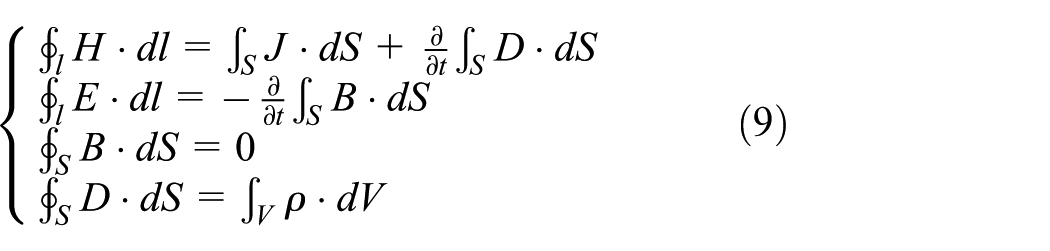
where H is the magnetic field intensity, J is the current density, D is the electric displacement vector, E is the electric field strength, B is the magnetic induction, and ρ is the charge density.
Based on the above equations, the relationship between different field quantities is derived as follows

where ε is the dielectric constant, µ is the permeability, and σ is the conductivity.
The electromagnetic wave equation is obtained by combining two wave equations, which take the magnetic vector potential A and scalar function ϕ as the variable function 27

The simulation results such as the model subdivision, magnetic force line distribution, the magnetic flux density modulus value, and the magnetic flux density vector are shown in Figures 12–15, respectively, after the mesh generation of finite element model, setting of the magnetization direction, and application of load and boundary conditions.28,29

Subdivision of model diagram.

Magnetic force line distribution diagram.

Magnetic flux density modulus value diagram.

Magnetic flux density vector diagram.
Based on the analysis on the finite element, it is found that the magnetic field in the rotor, stator yoke portion, and stator tooth is not saturated, and the strength of the air-gap magnetic field is 1.9 T, which meets the design requirements. There is a small amount of magnetic flux leakage at the top of the PM, but it is not serious. And the distribution of the magnetic field and magnetic alignment is more reasonable. The rotor is designed as a magnetic bypass structure, which can effectively prevent the demagnetization of Nd-Fe-B PM steel, take advantage of high coercivity of Nd-Fe-B permanent steel, and provide significant “magnetic gathering” effect.
Three-phase half-wave impulse-type controlled rectifier voltage regulator principle
Three-phase half-wave impulse-type controlled rectifier voltage regulator is combined by reference circuit, sampling circuit, trigger circuit, and the rectifier circuit.30,31 Soldered circuit board is fixed in a die-cast aluminum box and casted into a whole by unsaturated resin, which has the advantage of dust-proof, moisture-proof, anti-vibration, and impact resistance.32–34 The circuit diagram of the three-phase half-wave impulse-type controlled rectifier voltage regulator is shown in Figure 16.
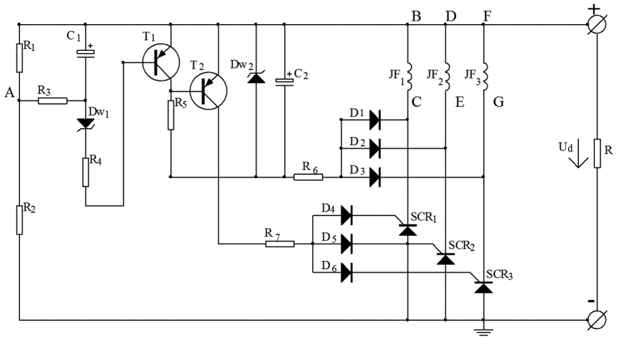
Three-phase half-wave impulse-type controlled rectifier voltage regulator circuit diagram.
The target voltage value U0 of the electronic regulator can be set at 14 V by changing the electric potential at the point A which is achieved through resistance adjustment of R1. Same armature windings are used in the three-phase PM alternator (JF1–3), which has a phase difference of 120°. The head termination of JF1–3 is connected as the positive side of the electronic rectifier regulator. The positive pole of SCR1–3 is connected as the negative side of the electronic rectifier regulator.
When the generator starts to rotate, the output voltage Ud is small and less than the defined target value U0 due to the low rotational speed. Since the voltage between triode T1 and point A is lower than the breakdown voltage of the regulator Dw1, triode T1 is in the off state. Stabilivolt Dw2 and capacitance C2 provide a positive bias voltage for triode T2, and the voltage between the emitter and the base of triode T2 is larger than 0.7 V. Therefore, triode T2 is in conduction state.
When the head termination B of the armature winding JF1 is the positive pole, the end termination C is the negative pole, and the potential of the head terminal B of JF1 is larger than the potential of the head terminal D in JF2 and the head terminal F in JF3, the trigger circuit current flows as follows: B → transistor T2 → resistors R7 → diode D4, which can supply trigger current to the gate of thyristor SCR1. After the conduction of the thyristor SCR1, the load current flows as follows: B → load R → thyristor SCR1 → C, which forms a closed loop and outputs DC. The target voltage value U0 of the electronic regulator can be set at 14 V by changing the electric potential at point A which is achieved through resistance adjustment of R1.
Same armature windings are used in the three-phase PM alternator (JF1–3), which has a phase difference of 120°. The head termination of JF1–3 is connected as the positive side of the electronic rectifier regulator. The positive pole of SCR1–3 is connected as the negative side of the electronic rectifier regulator.
When the generator starts to rotate, the output voltage Ud is small and less than the defined target value U0 due to the low rotational speed. Since the voltage between triode T1 and point A is lower than the breakdown voltage of the regulator Dw1, triode T1 is in the off state. Stabilivolt Dw2 and capacitance C2 provide a positive bias voltage for triode T2, and the voltage between the emitter and the base of triode T2 is larger than 0.7 V. Therefore, triode T2 is in conduction state.
When the head termination B of the armature winding JF1 is the positive pole, the end termination C is the negative pole, and the potential of the head terminal B of JF1 is larger than the potential of the head terminal D in JF2 and the head terminal F in JF3, the trigger circuit current flows as follows: B → transistor T2 → resistors R7 → diode D4, which can supply trigger current to the gate of thyristor SCR1. After the conduction of the thyristor SCR1, the load current flows as follows: B → load R → thyristor SCR1 → C, which forms a closed loop and outputs DC.
When the head termination D of the armature winding JF2 is the positive pole, the end termination E is the negative pole, and the potential of the head terminal D of JF2 is larger than the potential of the head terminal F in JF3 and the head terminal B in JF1, the trigger circuit current flows as follows: D → transistor T2 → resistors R7 → diode D5, which can supply trigger current to the gate of thyristor SCR2. After the conduction of the thyristor SCR2, the load current flows as follows: D → load R → thyristor SCR2 → E, which forms a closed loop and outputs DC.
When the head termination F of the armature winding JF3 is the positive pole, the end termination G is the negative pole, and the potential of the head terminal F of JF3 is larger than the potential of the head terminal B in JF1 and the head terminal D in JF2, the trigger circuit current flows as follows: F → transistor T2 → resistors R7 → diode D6, which can supply trigger current to the gate of thyristor SCR3. After the conduction of the thyristor SCR3, the load current flows as follows: F → load R → thyristor SCR3 → G, which forms a closed loop and outputs DC.
With the increase in generator speed, the output voltage Ud and the voltage between triode T1 and the point A are also increased. When the output voltage Ud is larger than the defined target voltage U0, the voltage between triode T1 and point A becomes larger than the breakdown voltage UW1 of the stabilivolt Dw1, which switches the state of triode T1 from off to on. The voltage between the emitter and collector is 0.2–0.3 V, which is lower than the threshold voltage between the emitter and the base of triode T2 (0.7 V). Triode T2 is switched off and stops to supply trigger current to the gate of SCR1–3. The cut-off of the silicon-controlled rectifier is delayed until there is no positive voltage. The three-phase half-wave impulse-type controlled rectifier voltage regulator circuit is disconnected immediately, which becomes open-circuit state. The output voltage Ud drops rapidly, and the voltage between triode T1 and point A drops accordingly. When the output voltage Ud is lower than the defined target voltage U0, triode T1 is switched off and T2 is switched on. Therefore, silicon-controlled rectifier is switched on, and the rectifier circuit is recovered to work again.
If the output voltage Ud increases and becomes larger than the defined target voltage U0, the stabilivolt Dw1 breakdowns, triode T1 is switched on, and T2 is switched off. This process is iterated, and triodes T1 and T2 are in on and off state repeatedly.
Based on the phase shifting, clipping, and rectifying, the output of DC from three-phase half-wave impulse-type controlled rectifier voltage regulator with stable voltage is ensured, which can be used to supply DC power to the vehicle charging facilities or charge the battery directly.
Performance test
In order to validate the performance of the developed Nd-Fe-B PMG, the generator test is performed with various rotary speeds and load power. The basic parameters of the tangential magnetic field of PMG are selected as follows: nominal voltage = 14 V, rated power = 500 W, and rated speed = 4000 r/min. The material of the PM is selected as Nd-Fe-B NTP-240SH 35 with the remanent flux density Br of 1.12 T, magnetic field strength Hc of 804 kA/m, and maximum energy product (BH)max of 223 kJ/m3.
The test is conducted on the newly developed three-phase half-wave impulse-type controlled rectifier voltage regulator Nd-Fe-B PMG from low rotary speed to high rotary speed with the load power of 480, 500, and 520 W. The test results are shown in Table 1.
Test results of the generator output voltage.

It is found from Table 1 that the output voltage maintains around 12.30–14.32 V for the generator speed of 2000–4800 r/min and load power of 480–520 W, which meets the design requirements.
Conclusion
The influence rule of the structural parameters of the tangential magnetic field of PMG on the leakage flux and leakage coefficient was analyzed. Based on the analysis, the optimal design parameters of the generator were obtained as follows: pole number = 4, thickness of the permanent steel = 4 mm, width of the magnetic isolation air = 4 mm, and air-gap length = 0.5 mm.
The Nd-Fe-B PM rotor was designed and used in the generator. It has the advantage of no electric field winding, low power consumption, high power generation efficiency, no carbon brush slip ring structure, and low failure rate. A three-phase half-wave impulse-type controlled rectifier voltage regulator was developed with the function of the regulator and rectifier, which proposes a solution to the output voltage instability of the Nd-Fe-B PMG in a wide speed and wide load range.
In order to validate the performance of the developed Nd-Fe-B PMG, the generator test was performed with various rotary speeds and load power. When the generator speed changes from 2000 to 4800 r/min and the load power varies from 480 to 520 W, the output voltage maintains around 12.30–14.32 V, which has an excellent regulator performance.
Footnotes
Academic Editor: Nasim Ullah
Declaration of conflicting interests
The author(s) declared no potential conflicts of interest with respect to the research, authorship, and/or publication of this article.
Funding
The author(s) disclosed receipt of the following financial support for the research, authorship, and/or publication of this article: This work was financially supported by Natural Science Foundation of Shandong Province under grant no. ZR2013EEL016 and no. ZR2012EEM011 and National Natural Science Foundation of China under grant no. 51405075.