
Abstract
A new type of drill bit designed with an annular slit was developed to enhance the reverse circulation effect of the down-the-hole hammer drilling technology. A computational fluid dynamics code, Fluent, was used to simulate the flow phenomena inside the drill bit. The simulation results show that the air flowing through the annular slit moves upward along the wall of the central passage of the annular drill bit and that there is no interference phenomenon similar to the normal drill bit, which is beneficial for the formation of reverse circulation. Meanwhile, the new drill bit with the annular slit was produced and tested in the laboratory. The results show that for the annular drill bit with the flushing nozzles closed, the mass flow rate of the sucked air is approximately 63.78 g/s, which is 1.76 times that of the normal drill bit, while it is about 2.46 times if the flushing nozzles are opened. In addition, many factors can affect the reverse circulation effect of the annular drill bit, including the slit width, the distance between the annular slit and the working surface of the drill bit, and the flow direction of the gas ejected from the annular slit.
Keywords
Introduction
Pneumatic down-the-hole (DTH) hammer drilling with reverse circulation is a fast and cost-efficient method of retrieving high-quality samples from exploration and mine drilling. It utilizes compressed air as the circulating fluid to carry the rock cuttings in a reverse circulation manner. Compressed air flows through the dual channel swivel, the annular space of the double-wall drill pipes, and the hollow through the DTH hammer, making the high-frequency impulse motions. Then, air is forced into the grooves of the drill bit and carries cuttings and core samples through the center of the drill bit into the inner central space of the double-wall drill pipe and then up to the surface.1,2 Continuous formation samples are returned to the surface from the discharge hose as drilling proceeds and can be collected and monitored at the surface. 3 Meanwhile, representative samples can be obtained with a high recovery rate, which have not been contaminated with drill additives or mixed with other borehole material because the cuttings travel directly from the drill bit through the steel inner tubes.4,5 Moreover, this drilling technology enhances the penetration rate in hard formations and addresses the problem of circulation loss in unconsolidated formations with cavities because there is normally no fluid or cuttings flow against the walls after the drill bit has passed.6,7 Therefore, it has been widely used in mineral deposit exploration, oil and gas drilling, hydrological drilling, underground water wells, civil engineering construction, and other drilling operations around the world. 8
The effectiveness of the reverse circulation DTH hammer drilling technology depends on whether the air flushing can exhaust nearly in its entirety into the center channel of the drill to form the reverse circulation especially in broken or fractured formation. So, the drill bit with a particular structure is the key component in this drilling technique. There are a variety of DTH hammer manufacturers with different proprietary air hammer and drill bit designs.9,10 For example, many studies from companies such as Atlas Copco and Halco Drilling International Limited have designed reverse circulation drill bits with a sealing ring described as a shroud, sleeve, or compensator ring, which has a larger diameter than a hammer casing.11,12 This shroud is mounted on the bit chuck to decrease the annular clearance between the borehole wall and the drill bit and to form a seal or near-seal to prevent cuttings from going up the outside of the drill bit instead of up through the central inner tubes. When the drill bit is worn away, the shroud can be replaced to match the size of the bit. There are also several types of reverse circulation drill bits designed with internal jetting nozzles.13–15 When exhausted air is ejected from these nozzles, a low/negative pressure zone can be created at the central passage of the drill bit, drawing airflow upward from the bottom surface of the drill bit. In the early 1990s, the reverse circulation DTH hammer drilling technology was developed in China. A special structure of the drill bit with some bottom flushing nozzles and inner suction nozzles was designed based on the principle of the gas ejector 16 as shown in Figure 1(a). Since then, many studies have been conducted to optimize this bit structure to improve the reverse circulation effect. For example, Ren et al. 17 designed a set of experimental apparatus to test the influence of the suction nozzles on the drill bit’s ability of taking core and carrying power. Yin et al. 18 used computational fluid dynamics (CFD) software to analyze the influence of the number and inclination angle of the suction nozzles on the reverse circulation. Zhao et al. 19 utilized engineering fluidic dynamics technology to study the effect of both the inner suction and the bottom flushing nozzle structures on reverse circulation.

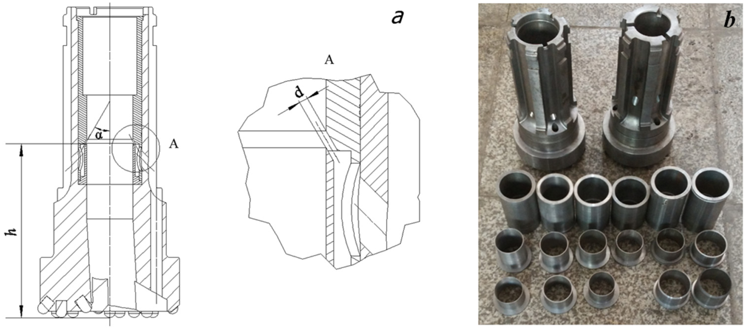
The reverse circulation DTH drill bit: (a) normal drill bit; and (b) new type of drill bit with an annular slit.
However, normal circulation still exists for rock cuttings carried through the annular space between the drill pipe and borehole in some conditions especially in ultra-broken formation, which causes low sample recovery rates and environmental contamination. So, it is important to improve the structure of the drill bit to enhance the effect of the reverse circulation. Currently, an annular slit has been successfully used in many fields including the Coanda ejector, spiral flow generator, and air jet pump. Compared with a normal nozzle, an annular slit can generate a large negative pressure and a large suction effect.20–22 Therefore, to improve the reverse circulation effect, a new type of drill bit with an inner annular slit was designed in this study. A CFD code, Fluent, was employed to simulate the flow phenomena inside the drill bit. Meanwhile, a series of tests were performed to investigate the influence of the annular slit on the reverse circulation effect. By comparison, the normal drill bit with the suction and flushing nozzles was also designed and tested in this article.
Design of the annular reverse circulation drill bit
Figure 1(a) shows the structure of the normal reverse circulation drill bit. There are two groups of nozzles inside the drill bit. One group with pressure restoring grooves at the outlet, called flushing nozzles, is designed vertical to the bottom surface of the drill bit. When the air is exhausted from the DTH hammer flowing out of these nozzles, it will sweep the cuttings toward the center passage of the drill bit and cool it. The other group of nozzles is called suction nozzles and is designed to intercept with the center passage of the drill bit. The high-speed air stream emerging from these suction nozzles will cause the pressure nearby to decrease. Driven by the pressure difference between the central passage of the drill bit and the annulus between the drill and the borehole, the cuttings generated as drilling proceeds are continuously drawn into the central passage of the drill bit and then upward to the surface. The greater the pressure difference, the more air is sucked from the annulus into the central passage, and the better the reverse circulation effect. However, the practical effect of this type drill bit is not very good because the air ejected from different suction nozzles interfere with each other, which results in large energy loss. In field applications for this type of drill bit, the normal circulation often co-exists with the reverse circulation. Sometimes all of the flushing nozzles have to be sealed to force the air to erupt from the suction nozzles, even though the tungsten carbide inserts cannot be effectively cooled with this method. 23
To solve this problem, a new type of drill bit was designed with the characteristic of two special pipes installed in its central passage as shown in Figure 1(b). An annular slit is formed between these two pipes called the built-in pipe and the built-in step, respectively. When the air ejects from this annular slit at a high speed, it causes the pressure nearby to decrease, and thereby, the reverse circulation is created. In addition, the air will flow upward along the inner wall of the built-in pipe, with no interference phenomena.
CFD research
Computation models
As discussed above, many studies have been conducted to optimize the structural parameters of the normal reverse circulation drill bit. Based on these results, the drill bit is designed to drill a borehole with a diameter of 186 mm, and the outer diameter of its body is 180 mm. So, the clearance between the drill bit body and the borehole wall is 3 mm. A total of six inner suction nozzles and three bottom nozzles are designed with the same diameter of 8 mm. The axial angle of the suction nozzles measured from the vertical position is approximately 30°. The diameter of the central passage of the drill bit is approximately 60 mm, and the distance between the working face of the drill bit and the borehole bottom is 8 mm. For the new annular drill bit, the width of the annular slit is 1.0 mm, and the diameter and the axial angle of the suction nozzles are 15 mm and 45°, respectively. The other parameters are nearly the same as the normal drill bit. For simplicity, the bottom of the borehole is represented by a horizontal circular plane, while the space occupied by the tungsten carbide inserts within the drill bit is ignored.
The geometry models of the drill bits were built using the Autodesk Inventor software. Then, they were imported to the Ansys Workbench software to mesh. A CFD code, Fluent, was used to conduct the numerical analysis. Several mesh densities were examined from finer to coarser, and the dense meshes were preset at the area of high flow rate and a high-pressure gradient to obtain accurate results. The final structured mesh consisted of approximately 1.6 million cells. To reduce computer costs and data manipulation time, ideal gas was used in the analysis. Figure 2 shows the computation models and the boundary conditions of the drill bit. A mass flow inlet was applied to the boundary of the drill bit inlet. The initial mass flow rate was approximately 0.1225 kg/s. That is, the airflow rate at the inlet boundary was approximately 6 m3/min under standard conditions, which was the nominal capacity of the air compressor in our laboratory. The pressure-outlet condition with atmospheric pressure has been chosen at the central passage exit of the drill bit. If the reverse circulation effect of the drill bit is not good, part of the gas will escape from the annular space between the drill bit and the borehole wall. So, the pressure outlet with atmospheric pressure was also used in this annular space boundary. If the reverse circulation effect is such that the air is sucked into the drill bit from the environment, the value of the airflow rate at this boundary should be positive with a means of air flow into the analysis model. The realizable version of the k–ε model was selected to model the turbulent viscosity by applying the coupled implicit solver. The near-wall treatment was left as the standard wall function, which gives reasonably accurate results for the wall bounded with a very high Reynolds number flow. The second-order upwind discretization was used for convective terms, and a central difference scheme was used for diffusion terms.

Computation models of the reverse circulation drill bits.
CFD results
Figure 3 shows the velocity distribution contours at a representative longitudinal section of the drill bit. It can be seen that the flow phenomenon is obviously different between two types of drill bits. For the normal drill bit, some of the gas ejects from different suction nozzles at high velocity, causing the pressure nearby to decrease. Then, these air streams are intertwined together in the front of the nozzles. Other gas emerged from the flushing nozzles as high kinetic energy enters into the central passage and moves upward at the pressure difference. This working process is similar to that of the ejector.24,25 The airflow from the suction nozzles acts as working fluid or primary fluid, while the air ejected from flushing nozzles works as secondary fluid. For the new type of drill bit, the air stream flows through the annular slit at a high speed and moves upward along the wall of the central passage, and the negative pressure is created in the center of the central passage. There is no interference phenomenon similar to that of the normal drill bit.

Velocity contours at longitudinal section of the drill bit: (a) the normal drill bit; and (b) the new type of drill bit.
Figure 4(a) gives a comparison of the static pressure distribution curves along the center axis. The negative pressure can be formed inside it for both types of drill bits. The lowest value of the pressure is approximately −2.7 and −3.5 kPa for the normal drill bit and the annular drill bit, respectively. Moreover, the pressure is gradually recovered to ambient pressure along the central passage of the annular drill bit, while it has a sudden change near the suction nozzles due to the emergence of the high-speed air streams for the normal drill bit. Figure 4(b) shows the pressure distribution at the centerline of the cross section with a distance of 5 mm from the borehole bottom. The negative pressure can be created at the bottom beside the area near the flushing nozzles. The suction ability of the annular drill bit is better than that of the normal drill bit because the pressure created by this type bit is lower than that of the normal drill bit.
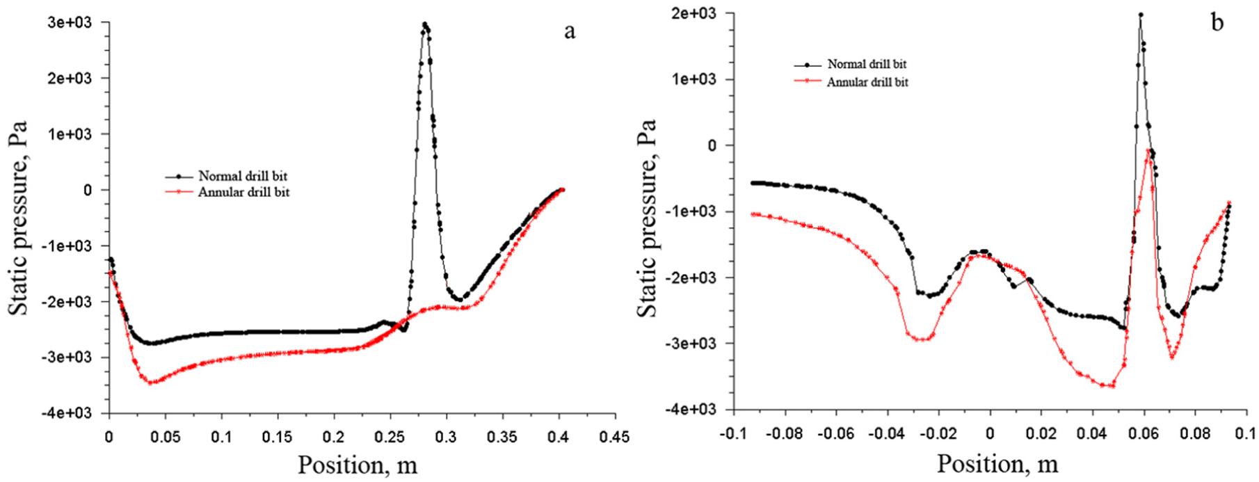
Comparison of the static pressure curves: (a) central axis of the drill bit and (b) centerline of the cross section with a distance of 5 mm from the borehole bottom.
The mass flow rates in each model boundary are described in Table 1. It can be seen that the values of the mass flow rate at the annular outlet boundary are positive for both types of drill bits, which means the air flows into the model through this boundary. While it is negative in the central outlet boundary, the air flows out of the model. That is, reverse circulations are formed. The mass flow rate at the annular outlet of the new annular drill bit is approximately 0.0573 kg/s, which is 1.81 times higher than that of the normal drill bit. So, the suction ability of the annular drill bit is higher than that of the normal drill bit, which means that its reverse circulation effect is better.
Mass flow rates in each boundary of the drill bit model.

Testing and discussion
Reverse circulation testing stand
To test the real effect of the reverse circulation drill bit, a special testing stand was designed as shown in Figure 5. The gas inlet channel is formed between the outer pipe and the inner barrel. Through it, the air stream coming from the air compressor enters into the reverse circulation drill bit to circulate. The second channel formed between the outer pipe and the casing is opened to the environment at the outlet of the connector pipe, which is equivalent to the annular space between the borehole and the drill. When the reverse circulation drill bit is working, the environment gas is sucked into the drill bit through this channel. All gas is blown out to the environment via the central passage of the inner barrel and the discharge pipe. The normal and annular reverse circulation drill bits were designed with the same size used in the CFD analysis. The exposure of the inset carbide buttons is approximately 8 mm for both types of drill bits. The annular space between the drill bit and the casing is approximately 3 mm. The 2VFC-6/8 air compressor is used to supply high-pressure air, and the capacity of the flow rate is 6 m3/min and the pressure is 0.8 MPa. An air tank with a volume of 1.2 m3 is employed to reduce the fluctuation in air pressure, which is connected between the air compressor and the testing device. To investigate the influence of the airflow rate on reverse circulation, a flow dividing passage is installed between the air tank and the testing device to adjust the volume flow rate of air entering into the testing device.

Testing stand of reverse circulation drill bit.
Several parameters including the airflow rates, air pressure, and borehole bottom pressure are continuously measured and recorded at 1-s intervals during testing. A LK-062 pressure sensor installed in the base frame is used to measure the bottom pressure of the drill bit. Its measure range is approximately −100 to 500 kPa, and the precision is 0.25% full scale (FS). A vortex shedding flow meter with an LK-VFF-50 type and installed in the inlet of the connector pipe is employed to measure the flow rate of the air sucked into the drill bit. The range and the precision of this flow meter are 0.1–100 g/s and 1.5% FS, respectively. An LZM-25Z float type flow meter with a range from 25 to 250 m3/h is used to measure the air volume discharged from the divide passage.
The data for the main parameters are transmitted and stored in a computer. At the same time, it can be displayed in graphic form on the screen.
During testing, the mass flow rate of the air sucked into the drill bit was used to describe its reverse circulation performance. By considering that the flushing nozzles are sealed in certain cases for the field application, hot melt adhesive sticks were used to seal them during testing.
Results comparison between the normal drill bit and the annular drill bit
The speed of the air stream jetting from the suction nozzles or annular slit increases as the input air volume flow rate rises. The pressures nearby decrease accordingly under the effect of gas entrainment. So, the suction effect is enhanced with them, which results in more air being sucked into the drill bits. Therefore, the sucked air mass flow rate increases with an increase in the input air volume flow rate for both types of drill bits as shown in Figure 6. When the input air volume flow rate increases from 2 to 6 m3/min, the pressure of the borehole bottom reduced from −0.07 to −2.29 kPa and −0.02 to −3.71 kPa for the normal drill bit and the annular drill bit without flushing nozzles, respectively. Correspondingly, the mass flow rate of the sucked air was improved from 17.18 to 36.21 g/s and 34.22 to 63.87 g/s. When the volume flow rate of the air supply is 6 m3/min, the sucked air mass flow rate of the annular drill bit without flushing nozzles is approximately 1.76 times the normal drill bit.

(a) Effect of air supply volume flow rate on suction air mass flow rate and (b) effect of air supply volume flow rate on pressure of borehole bottom.
For the drill bits designed with flushing nozzles, part of the gas will be ejected from the flushing nozzles, so the gas velocity flow from the suction nozzles will be reduced compared with conditions of the flushing nozzles closed. Therefore, the suction effect is weakened, and the air volume sucked into the drill bits decreased for both types of drill bits as shown in Figure 6. When the input air volume flow rate increases from 2 to 6 m3/min, the pressure of the borehole bottom reduced from −0.10 to −3.31 kPa and −0.14 to −4.52 kPa for the normal drill bit and the annular drill bit with flushing nozzles, respectively. Correspondingly, the mass flow rate of the sucked air was improved from 5.02 to 8.11 g/s and 14.74 to 20.02 g/s. It should be noted that the high-speed gas stream jetting from the flushing nozzles will cause the pressure nearby to decrease, so the pressure at the borehole bottom of the drill bits with the flushing nozzles is lower than those without flushing nozzles.
In a word, the reverse circulation effect of the annular drill bit is better than the normal drill bit no matter how the flushing nozzles are designed.
Influence of the annular slit parameters on reverse circulation effect
Many factors can affect the reverse circulation effect of the annular drill bit, including the width of the annular slit, the distance between the annular slit and the bottom surface of the drill bit, and the angle between the slit axis and the center axis of the drill bit, termed as d, α, and h, respectively. To test the influence of these parameters on the reverse circulation effect, many built-in pipes and built-in steps with different sizes are designed to form different structures of the annular slit as shown in Figure 7.
(a) Annular slit structure parameters of the annular drill bit and (b) different built-in pipes and built-in steps.
Effect of the annular slit width d
Keep the angle α as 0° and the annular slit height as 215 mm. The effect of the annular slit width d on the reverse circulation has been studied as shown in Figure 8. Under the conditions of large quantities of air supply, the flow resistance increases if the width is too small so that most of the gas is jetted from the flushing nozzles. Thus, the gas velocity emerging from the annular slit is reduced, which results in the weakening of the suction effect. Therefore, the mass flow rate of the sucked air decreases with an increase in the air supply when the width of the annular slit is approximately 0.5 mm as shown in Figure 8(a). For the same reason, the sucked air volume increases with an increase in the value d until d = 1.5 mm. Then, it begins to decrease with an increase in d value, when the volume flow rate of the air supply is approximately 6 m3/min.

Relationship between the mass flow rate and the width of the annular slit: (a) drill bit with flushing nozzles and (b) drill bit without flushing nozzles.
When the flushing nozzles of the drill bit are sealed, the gas can only flow out from the annular slit, so the mass flow rate of the sucked air increases as the air supply increases as given in Figure 8(b). Moreover, the sucked air volume increases from 48.40 to 63.87 g/s with an increase in the value d from 0.5 to 1.0 mm. Then, it is reduced to 22.48 g/s when the width d decreases to 3.5 mm.
Effect of the annular slit height h
It is clear that the suction effect will be enhanced if the annular slit is close to the bottom of the drill bit. Figure 9 gives the testing results when α = 0°, d = 1.0 mm, and when the height of the annular slit h is 215, 230, 240, and 255 mm, respectively.

Relations between the height h and the mass flow rate of sucked air: (a) drill bit with flushing nozzles and (b) drill bit without flushing nozzles.
It can be seen that the mass flow rate of sucked air decreases with an increase in the annular slit height. When the volume flow rate of the air supply is approximately 6 m3/min, the mass flow rate of the sucked air reduced from 20.02 and 63.87 g/s to 14.24 and 48.24 g/s for the drill bit with the flushing nozzles opened and sealed, respectively, with the value h increasing from 215 to 255 mm. Therefore, the annular slit should be designed near the suction nozzles as much as possible.
Effect of the annular slit angle α
The effects of the annular slit angle α on the mass flow rate of sucked air were investigated in this study by maintaining a constant slit width of 1 mm and the slit height of 215 mm. The testing results are presented in Figure 10. The mass flow rate of sucked air increases with an increase in the air supply and decreases with an increase in the annular slit angle α. When the volume flow rate of the air supply is approximately 6 m3/min, the mass flow rate of sucked air decreases from 20.02 and 63.87 g/s to 5.24 and 14.86 g/s for the drill bit with the flushing nozzles opened and sealed, respectively, with the value α increasing from 0° to 90°. The reason may be that the air ejected from the annular slit at a certain angle interferes with each other.

Relations between the annular slit angle α and the mass flow rate of sucked air: (a) drill bit with flushing nozzles and (b) drill bit without flushing nozzles.
Conclusion
Based on the structure of the normal drill bit designed with suction nozzles and flushing nozzles, a new type of reverse circulation drill bit used in DTH drilling was developed using an annular slit instead of suction nozzles. When the air ejects from the annular slit, it causes the pressure nearby to decrease and to form the reverse circulation.
CFD simulation results show that the air stream ejected from the suction nozzles are intertwined in front of the nozzles for the normal drill bit. However, for the annular drill bit, the air flow through the annular slit moves upward along the wall of the central passage, and there is no interference phenomenon similar to that of the normal drill bit. So, the pressure generated at the bottom by the annular drill bit is lower than that of the normal drill bit, which is beneficial in forming the reverse circulation.
The sucked air mass flow rate increases with an increase in the input air volume flow rate for both types of drill bits no matter how the flushing nozzles are designed. For the annular drill bit with the flushing nozzles closed, the mass flow rate of the sucked air is approximately 63.78 g/s, which is 1.76 times that of the normal drill bit. The annular drill bit is approximately 2.46 times that of the normal drill bit if the flushing nozzles are opened. Therefore, the reverse circulation effect of the annular drill bit is better.
Laboratory testing results show that the optimum value exists for the annular slit width. The gas velocity jetting from the annular slit will be reduced if the slit width is too small or too large, which results in a weakened suction effect. The distance between the annular slit and the working surface of the drill bit has a certain influence on the reverse circulation. It should be near the bottom as much as possible. Moreover, the flow direction of the gas ejected from the annular slit should be parallel to the central axis of the drill bit.
Footnotes
Acknowledgements
The authors thank anonymous reviewers for fruitful remarks and comments.
Academic Editor: Fakher Chaari
Declaration of conflicting interests
The author(s) declared no potential conflicts of interest with respect to the research, authorship, and/or publication of this article.
Funding
The author(s) disclosed receipt of the following financial support for the research, authorship, and/or publication of this article: This paper was supported by the National Natural Science Foundation of China (Project Nos 41576184 and 51174097) and the research programs of the science and technology department, Xinjiang Uygur Autonomous Region of China (Project No. 2013911033).