
Abstract
Assembly planning is normally realized by automatic approach or interactive approach. Both of these methods have promising advantages, but they also have inevitable shortcomings. This article proposes a hybrid approach to combine automatic assembly planning and interactive assembly planning to generate optimal assembly sequence for industrial products. By defining a novel precedence constraint table to represent the assembly precedence relationships between components, the initial feasible assembly sequence can be generated by intelligent algorithm. This assembly sequence can be interactively simulated and evaluated in a haptics-based virtual environment. By simulating the multiple geometry constraints–based assembly process and assembly tool operation process, more practical precedence constraints and evaluation rules can be recognized, and more optimal assembly sequence can be re-planned. This is an iterative process until the best assembly sequence is obtained. The proposed hybrid approach can utilize the advantages of both methods, such as computer intelligence and human knowledge, and overcome their shortcomings. The generated results are more practical and flexible than traditional methods.
Introduction
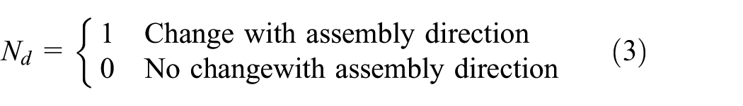
Generally, assembly planning can be classified into two types: automatic assembly planning and interactive assembly planning. The early automatic assembly planning methods are mainly based on geometric reasoning. According to the “assembly by disassembly” principle, the feasible disassembly sequence is the inverse of assembly sequence. 1 However, assembly planning is also a non-deterministic polynomial-time (NP)-hard combinatorial problem. When the number of components increases, the solution space is excessively increased and leads to combinatorial explosion problem. Many researchers try to use soft computing approach to solve assembly planning problem, and several intelligent algorithms have been used, such as genetic algorithm, 2 artificial neural network, 3 ant colony optimization (ACO) algorithm, 4 particle swarm optimization algorithm, 5 and imperialist competitive algorithm. 6 Also for automatic assembly planning, the most important evaluation objectives are minimizing the number of assembly direction changes, minimizing the number of assembly tool changes, minimizing the number of assembly type changes, and maximizing assembly stability and parallelism.
Virtual reality (VR) and haptics provide a new promising approach for assembly planning. As a typical application of VR in engineering, virtual assembly allows the designer to import concepts into virtual environment during the early design stage with interactive simulation, analysis, and evaluation. Haptics feedback is particularly important for virtual assembly because it can increase the users’ sense of immersion and interaction, help the users to get a better understanding of virtual objects and operation process, and therefore improve assembly task efficiency. Although several haptics-based assembly planning systems have been developed,7–11 it is still a challenging work for haptics-based assembly simulation because of the complexity of the physical processes and the limitation of the available haptic devices. Problems such as realistic and natural interaction between part-part and hand-part, dynamic simulation of part physical behavior, real-time collision detection with high precision parts, and guarantee of haptic feedback at a high update rate are attracting more and more researchers. However, there is still a long way to go before haptics-based assembly planning gets wide applications in industrial products.
Both automatic assembly planning and interactive assembly planning have many advantages and have been used for many products, for example, automatic assembly planning has the advantage of utilizing the power of computer intelligence to generate optimal or near-optimal assembly sequences, and interactive assembly planning has the advantage of utilizing human knowledge and experience. However, both of these approaches have inevitable shortcomings: (1) for automatic assembly planning, the low computation efficiency and the poor practicability are the main problems. Automatic assembly planning is mainly based on the adoption of a numerical global optimization algorithm and also takes into account the geometrical constraints and some heuristic rules to generate optimal or near-optimal assembly sequences. However, for industrial products, they are normally consisted by tens of thousands of components. On one hand, when the number of parts increases, there will be combinatorial explosion problem which leads to long computation time and poor convergence performance. On the other hand, automatic assembly planning is mainly based on automatic reasoning according to the evaluation of geometrical relationships among parts or heuristic rules with some simplified affecting factors such as assembly direction change and assembly tool change. However, many other important affecting factors, such as the operation space limitation, assembly tool accessibility, the vision obstruction, ease of measurement, the human activity and ergonomics problem, cannot be taken into account. Therefore, the results generated from automatic assembly planning are difficult to be used for the actual assembly production because of poor practicality and flexibility. (2) For interactive assembly planning, the main process is to assemble the components one by one according to human experience and knowledge, and then get a complete assembly sequence. However, it is a long and tedious process to assemble the components step by step as building the blocks if the number of components is big, and also, it will be difficult for the user to judge all the feasible assembly parts at each step and to correctly evaluate the assembly quality, which will lead to heavy cognitive load because the mechanical structures of industrial products are so complicated. At the same time, because of the limitations of human experience and knowledge, for different persons, their assembly experience and knowledge will be different, and therefore, the generated assembly plans may also be different, which is easy to change the subject to human subjective judgment. Therefore, interactive assembly planning has the disadvantages of blindness and uncertainty, which needs intelligent guide and optimization. Normally, the results generated from interactive assembly planning are feasible assembly sequences, but not optimal or best assembly sequences.
The proposed hybrid approach
A hybrid approach combining automatic assembly planning and interactive assembly planning together has been proposed, which can utilize the advantages of both methods and avoid their shortcomings. On one hand, based on intelligent optimization algorithm, the automatic assembly planning can utilize the power of computer intelligence to generate the initial optimized assembly sequence. On the other hand, based on haptics-based virtual assembly simulation, the interactive assembly planning allows the user to simulate, analyze, and evaluate the initial optimized assembly sequence. During simulation and evaluation, new evaluation rules and precedence constraints will be recognized, which can be used for automatic planning to generate more optimized assembly sequence. This is an iterative process until the best assembly sequence can be obtained. The detail of the proposed approach can be described by the following steps:
Step 1. The assembly model of the product is designed in computer-aided design (CAD) system such as SolidWorks and Pro/Engineering.
Step 2. Data transformation from CAD system to VR system. The information decomposition and transformation method 9 is used to extract the geometry information, topology information, and assembly information from CAD model and then loaded into VR environment.
Step 3. A hierarchical constraint-based assembly model and a hierarchical scene graph can be constructed, which can be used to support interactive assembly and disassembly simulation. 8
Step 4. According to CAD model and assembly connection relationship, the precedence constraint table can be defined, which will be discussed in section “Representation of precedence constraint.”
Step 5. According to human assembly experience and knowledge, the initial evaluation rules can be generated, which include assembly tool rules, assembly direction rules, and the user-defined evaluation rules.
Step 6. ACO-based intelligent assembly planning generates initial optimized assembly sequences, which will be discussed in section “Automatic assembly planning.”
Step 7. The initial optimized assembly sequence can be simulated, analyzed, and evaluated in a haptics-based virtual environment. A hybrid approach combining geometry constraint and physics modeling has been realized for haptics-based assembly simulation, which will be discussed in section “Haptics-based interactive assembly simulation.”
Step 8. During haptics-based interactive assembly simulation, new precedence constraints and evaluation rules will be recognized, and a knowledge base can be developed, which will be discussed in section “Knowledge base for the evaluation rules.” The user can add new precedence constraints, update the existing precedence constraints, add new evaluation rules, or adjust the penalty value for the existing rules.
Step 9. Based on the new recognized precedence constraints and evaluation rules, the user can re-plan the assembly process to get more practical and optimal assembly sequence. This is an iterative process until the best assembly sequence can be obtained.
The innovation of the proposed approach can be summarized as follows: (1) it provides a practical and efficient hybrid framework which can utilize the advantages of automatic assembly planning and interactive assembly planning and overcome their shortcomings; (2) it provides a novel representation of assembly precedence constraints, which can be directly integrated with the intelligent algorithm to improve the performance of automatic assembly planning; and (3) it proposes a hybrid method combining geometry constraint with physics modeling to realize haptics-based assembly simulation and haptics-based tool operation simulation. Therefore, the designer can exert their assembly-related experience and knowledge to perform interactive assembly/disassembly operation, analyze assembly space limit and tool accessibility, evaluate human-related factors and ergonomics, and then generate more practical precedence constraints and evaluation rules for the assembly knowledge base. Based on the knowledge base, the more practical and optimal assembly sequence can be planned.
Design and implementation
Representation of precedence constraint
Assembly planning is mainly based on precedence constraints, which show the relation of predecessor and successor components during assembly process. Normally, assembly precedence constraints can be divided into two types: absolute constraints and optimization constraints. The absolute constraints refer to the mandatory constraints which must be satisfied by all assembly sequences; otherwise, the assembly sequences will become infeasible. For example, during assembly process, some parts must be assembled before the other parts; otherwise, there isn’t collision-free trajectory to bring the part in contact with the other mating part. Meanwhile, the optimization constraints are not mandatory for all the assembly sequences. If an assembly sequence violates the optimization constraints, it is still feasible; however, it will affect the quality of the assembly process. Normally, the optimization constraints are related to the optimization objectives of assembly planning, such as assembly tool constraint, assembly direction constraint, assembly stability constraint, human ergonomics constraint, assembly safety constraints, and the specific constraints defined by the user. Precedence constraints can be represented by precedence diagram or matrix form. Here, a precedence constraint table is defined to represent the absolute precedence constraints.
Definition
Precedence constraint table is an n × n table which is used to record and represent the assembly precedence relationships between parts. The row headings ai (1 < i < n) and column headings aj (1 < j < n) denote the parts of product, and each element in the table, aij, represents the precedence relationship when assembling ai with aj:
If the value of aij is 0, it means that there is no assembly relationship between part ai and aj.
If the value of aij is 1, it means that there is assembly relationship between part ai and aj.
If the value of aii is 1, it means that ai is the base part for assembly.
If the value of aij is “>xi,” it means that the assembling of ai and aj must be before the reference connection of xi. If the value of aij is “≥xi,” it means that the assembling of ai and aj must be no later than the reference connection of xi. All the assembly precedence constraints can be represented by the operator “>” and the operator “≥.” 12
Reference connection xi is a mark which is defined for the convenience of representing assembly precedence constraints. The assembling of any two parts which have connection relationship can be defined as reference connection.
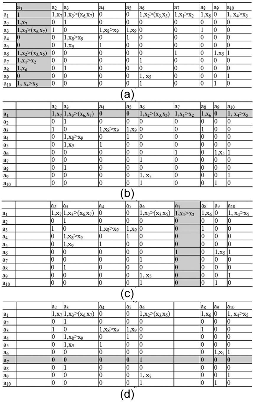
As an example, Figure 1 is a product with 10 parts (a1, a2, …, a10) and its liaison graph, and Table 1 is the precedence constraint table. Because a1 is the base part which should be assembled first, the value of a11 is equal to 1. The assembling of a2 and a1 is defined as the reference connection x7, the assembling of a8 and a1 is defined as the reference connection x6, and the assembling of a3 and a1 is defined as reference connection x3. For example, the value of a13 is “x3>(x6, x7),” it means that the assembling of a3 and a1 must be before the assembling of a8 with a1 and the assembling of a2 with a1.

A product and its liaison graph.
Precedence constraint table.

Assembly precedence constraints can be generated by geometry reasoning, interactive disassembly, or by answering a series of user-defined questions. However, in this article, the initial assembly precedence constraints are generated from directional blocking graph 12 and then the new assembly precedence constraints can be recognized by haptics-based interactive simulation and evaluation.
Automatic assembly planning
ACO is inspired by the behavior of real ant colony in searching food. Real ants are capable of finding the shortest path from their nest to a food source without using visual cues by exploiting pheromone information. The basic idea of ACO-based automatic assembly planning is to use ACO algorithm to generate one or several near-optimal assembly sequences to guide the assembly process of complex products. A feasible assembly sequence corresponds to a path from the nest to the food source, and the first assembly part (base part) corresponds to the nest. The assembly cost corresponds to the length of the path. All the ants start from the base part, and then according to the precedence constraints select the next part. After the ant traverses all the parts, a feasible assembly sequence is generated. According to the pheromone trail updating mechanism, when all the ants converge to one or several shortest paths, the optimal or near-optimal assembly sequences can be obtained.
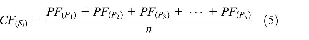
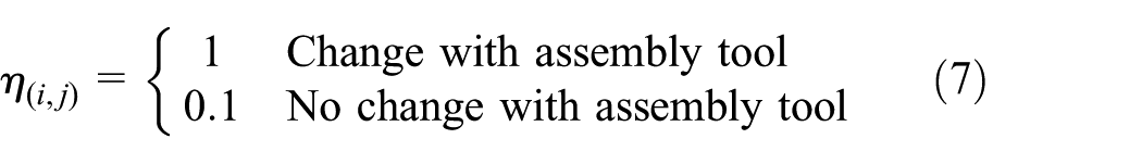
The penalty strategy is used to evaluate the assembly sequence. Three types of evaluation rules are used: the assembly direction rule, the assembly tool rule, and the user-defined rules. Normally, the minimum number of assembly direction changes means less assembly time and cost; therefore, if the direction of next part is different from the current direction, a penalty value is assigned. Similarly, if the next part requires different tool with the current part, a penalty value will also be assigned. At the same time, during haptics-based virtual assembly simulation, a series of evaluation rules thinking about assembly accessibility, assembly tool operation space, human ergonomics and safety, and so on can be defined. If the assembly sequence violates the user-defined evaluation rules, a penalty value will also be assigned according to the importance for assembly time, cost, or quality. Finally, when a part

where


Therefore, the cost function for assembly sequence
where
The probability of selecting the next part

where


When the ant moves from the current node

where
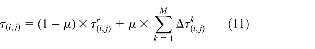
When all the ants finish the whole assembly process, the pheromone trails can be globally updated by
where

where Q is a constant parameter,
The ACO-based intelligent assembly planning process can be described as the following steps. The input is the precedence constraint table, and the output is one or several near-optimal assembly sequences:
Step 1. The number of ants is set as M and the initial pheromone value is set as
Step 2. The start point for all the ants is set at the base part, as shown in Figure 2(a), the base part is a1 for the product as shown in Figure 1.
Step 3. The column a1 is deleted from the precedence constraint table, as shown in Figure 2(b), because it has been selected as the base part in step 2.
Step 4. The possible available parts for the next step are the parts located at column ai which has been selected as the assembling part in the previous step and also aij is not 0. For example, as shown in Figure 2(a), the available parts after a1 are located at column a1 and also the value of aj1 is not equal to 0. That is to say, the available parts for the next step are a2, a3, a6, a7, a8, and a10.
Step 5. According to the precedence constraints, the unfeasible parts should be filtered from the set of available parts and then the feasible parts for next step are left. For example, because a31 is x3>(x6, x7), it means that a3 must be assembled before a8 and a2. Similarly, a6 must be assembled before a3 and a9, and a7 must be assembled before a6. So, finally, the feasible parts for the next step are a7 and a10.
Step 6. According to the probability defined by formula (6), a part is randomly selected from the set of feasible parts as the assembling part for the next step.
Step 7. As shown in Figure 2(c), a7 is selected as the assembling part for next step by probability.
Step 8. a7 is deleted from the precedence constraint table, as shown in Figure 2(d).
Step 9. Steps from 4 to 8 are repeated until all the parts are selected only once and a feasible assembly sequence is generated.
Step 10. The penalty value of the feasible assembly sequence is calculated according to the assembly tool change, the assembly direction change, and the user-defined evaluation rules.
Step 11. According to the assembly penalty value, all the ants update the pheromone trails on the path.
Step 12. Steps from 2 to 11 are repeated until the maximum iteration number is achieved or the assembly penalty value is not changed.
ACO-based intelligent assembly planning process: a1-base, a2-medium bolt, a3-cover, a4-washer, a5-short bolt, a6-long bolt, a7-connecting piece, a8-short bolt, a9-nut, and a10-washer.
Haptics-based interactive assembly simulation
Interactive virtual assembly simulation can be implemented by two different approaches: geometry constraint–based approach and physics modeling–based approach. 9 Geometry constraint–based approach uses the constraint solver to calculate the precise position and the reduced degrees of freedom (DOF) of the object to realize constraint-based motion simulation; however, physics modeling uses physical laws to simulate natural interaction and realistic behavior. Compared to physics modeling, geometry constraint method needs less computation cost and memory requirements, although its natural interaction and realistic object behavior are not perfect. However, for industrial products, because they include a large number of components which lead to millions of polygons in virtual environment, it is very difficult to realize dynamic simulation of part’s physical behavior. Ensuring the system performance for real-time collision detection and stable haptic rendering is the most important objective. Therefore, a hybrid approach combining physics modeling with geometry constraint has been realized here to simulate the interactive assembly process. Two issues are mainly discussed here: haptics-based assembly simulation with multiple geometry constraints and haptics-based assembly tool simulation.
Haptics-based assembly simulation with multiple geometry constraints
An improved virtual coupling method, which is originally proposed by S Garbaya and U Zaldivar-Colado, 10 has been implemented to simulate the part’s dynamic behavior. This virtual coupling method provides a dual representation for the operated part: the tracked model and the displayed model. The tracked model of the part is invisible for the user and controlled by the phantom device for collision detection and penetration depth calculation. The displayed model is visible to the user for graphic display. A mass-spring model, which is composed by a linear spring and torsion spring, is used to couple the tracked model and the displayed model. By applying the linear force and the torque to the displayed model, the realistic manipulation of parts can be obtained to visually prevent three-dimensional (3D) models to pass through each other, and the collision force and torque can be computed using the penetration depth of the tracked model of the operated part into the other parts. Therefore, the displayed model can keep following the tracked model moved by the operator with haptic device without the interpenetration of other parts.
However, when the operated part and the base part are close enough to each other and the distance and orientation of their assembly features reach a specified threshold, the hybrid approach of combining physics modeling with geometry constraint is activated. In order to avoid unnecessary computation and improve haptics efficiency, the collision detection is closed during this stage. The virtual part is adjusted to the precise assembly position by geometry constraint. At the same time, a real-time guiding force/torque or repulsive force/torque can be generated to make the user feel that he is assembling the virtual part as he would the real products. 8
Multiple geometry constraints are quite common for the assembly process of industrial products. Different from the single axis-hole mating process, the main issues of multiple geometry constraints–based assembly process simulation are how to avoid violating the previously applied geometry constraint while solving the current geometry constraint, and how to simulate the motion and behavior as realistic as the actual assembly process. An example, as shown in Figure 3, is used here to illustrate the haptics-based assembly process simulation with multiple geometry constraints, which can be described by the following steps:
Step 1. The axis-part is operated by the haptic device to move to the hole-part, the dynamic behavior of the axis-part is simulated by the virtual coupling method as shown in Figure 4. The linear spring is used to apply a translational force to the displayed model in order to follow the tracked model by performing translational movement. The torsional spring is used to apply a torque to the displayed model in order to keep the orientation of displayed model relative to the tracked model. When they contact each other, the collision force and torque can be computed by formulas (13) and (14), and the displayed model of the axis-part can be kept on the surface of the hole-part without interpenetration for visually realism


where
Step 2. If the axis-part is close enough to the hole-part, or the angle between the direction vector of axis-part and the direction vector of hole-part is within the threshold, and the distance between the direction vector of axis-part and the direction vector of hole-part is also within a threshold, then a geometry constraint of axis-hole mate can be captured, and the position and orientation of the displayed model is adjusted by geometry constraint, not just following the tracked model. As shown in Figure 3(a), if the geometry constraint of axis-hole mate 1 is recognized, the correct position and orientation of the displayed model of axis-part can be calculated and applied.
Step 3. A local coordinate system is defined as shown in Figure 3(b),


where
where
Step 4. During the rotation process, the displayed model of the axis-part is controlled by geometry constraint for visual realism. However, the tracked model of the axis-part is controlled by haptic device. If the tracked model of the axis-part deviates from the position and orientation of the displayed model, a repulsive force and torque can be also generated

where
Step 5. The user can rotate the axis-part around the Z axis of the first axis-hole mate by haptic device. When the second geometry constraint (axis-hole mate 2) is captured, the axis-part can be adjusted to the correct position without violating the first geometry constraint (axis-hole mate 1). The attractive torque and the repulsive force and torque can guide the user to operate the axis-part to get to correct position.
Step 6. After the second geometry constraint is satisfied, the orientation of the axis-part is fixed. When the user operates the haptic device to move the axis-part to the third geometry constraint (plane mate 3), the displayed model of the axis-part can only move along the direction of Z axis to keep the geometry constraints; however, the tracked model is controlled by the haptic device and it may deviate from the displayed model. When the orientation of the tracked model deviates from the orientation of displayed model, the maximum repulsive torque

Haptics-based virtual assembly simulation with multiple geometry constraints.

Mass-spring model between tracked and displayed part.
Haptics-based tool operation simulation
Tool operation simulation is also realized based on geometry constraints and physics modeling. Normally for common assembly tools such as screwdriver and wrench, the geometry constraints are mainly axis-alignment constraints and face-mating constraints, as shown in Figure 5. Therefore, haptics-based assembly tool simulation can be described in the following steps:
Step 1. The tool is moved by haptic device to the part, and the virtual coupling method with mass-spring model is also used to simulate the dynamic behavior of the tool.
Step 2. Rough orienting: as shown in Figure 5(a) left, when the tool is close enough to the part, the first geometry constraint (the axis-alignment between the axis of tool and the axis of bolt) is captured, and the tool is adjusted to the rough orienting position.
Step 3. Precise orienting: as shown in Figure 5(a) middle, the user can use the haptic device to rotate the tool to approach to the second geometry constraint (the face-mating between the side plane at the tip of the screwdriver and the side plane at the slot of the bolt). During the simulation process, because of the geometry constraint, the displayed model of the tool can be only rotated around the Z axis of the tool’s local coordinate system; however, the tracked model of the tool is controlled by the haptic device. When the tracked model deviates from the displayed model, a repulsive force and torque will be generated, and at the same time an attracting torque can be also generated to guide the tool to rotate to the correct orientation. If the second geometry constraint is captured, the tool can be adjusted to the precise orientation.
Step 4. Precise positioning: as shown in Figure 5(a) right, after precise orienting, the tool can be only moved to the final position without rotation. During the simulation process, the displayed model of the tool can be only moved along the Z axis; however, the tracked model of the tool can deviate from the displayed model. Correspondingly, a repulsive force and torque will be generated to prevent the deviation, and an attracting force will also be generated to help the tool to be located at the correct position. When the third geometry constraint (face-mating between the top plane of the tool and the top surface of the bolt) is captured, the tool is fixed to the precise position.
Step 5. Tool operation: when the tool is matched on the part, the part is attached with the tool together as a whole to move and rotate. The user can use the haptic device to simulate the tool operation process. The tool can only be rotated around the Z axis of its local coordinate system and also be moved along the Z axis with a small distance according to thread pitch, just as the real operation process of tool with nut or bolt. During the simulation process, if the tool collides with the other parts, an evaluation rule will be generated. Therefore, the transformation matrix of the tool operation can be calculated as
where


Assembly tool operation simulation by haptic device: (a) screwdriver and (b) wrench.
Similarly, the simulation of the wrench operation is shown in Figure 5(b), which is also realized by rough orienting, precise orienting, precise positioning process based on geometry constraint, and physics modeling.
Knowledge base for the evaluation rules
During haptics-based virtual assembly simulation, the user can exert assembly-related experience and knowledge, and then analyze and evaluate the assembly process interactively, visually, and perceptually. Three tasks must be taken into account during interactive simulation: (1) recognizing new precedence constraints. Some precedence constraints may be missing from CAD model with geometric reasoning. During simulation, if the user finds the assembly process is infeasible, the new precedence constraint will be recognized and added to the precedence constraint table. (2) Defining new evaluation rules. Generally, the evaluation rules include assembly safety rules, assembly stability rules, assembly efficiency rules, tool accessibility rules, ease of operation rules, and ease of measurement rules. After several loops of virtual assembly simulation, the evaluation rules will become more and more practical and complete. (3) Adjusting penalty value for evaluation rules. The definition of evaluation rules is also based on penalty strategy. If an evaluation rule is violated, a corresponding penalty value is assigned according to its effect to the assembly cost. These evaluation rules can be used to re-plan the more economic and practical assembly sequence. The system provides an interactive interface for the user to edit the existing evaluation rules, and adjust the penalty value for each evaluation rule, which can improve the practicality and flexibility of assembly planning process. An example of evaluation rules and their penalty value is shown in Table 2.
The assembly evaluation rules and their penalty values.
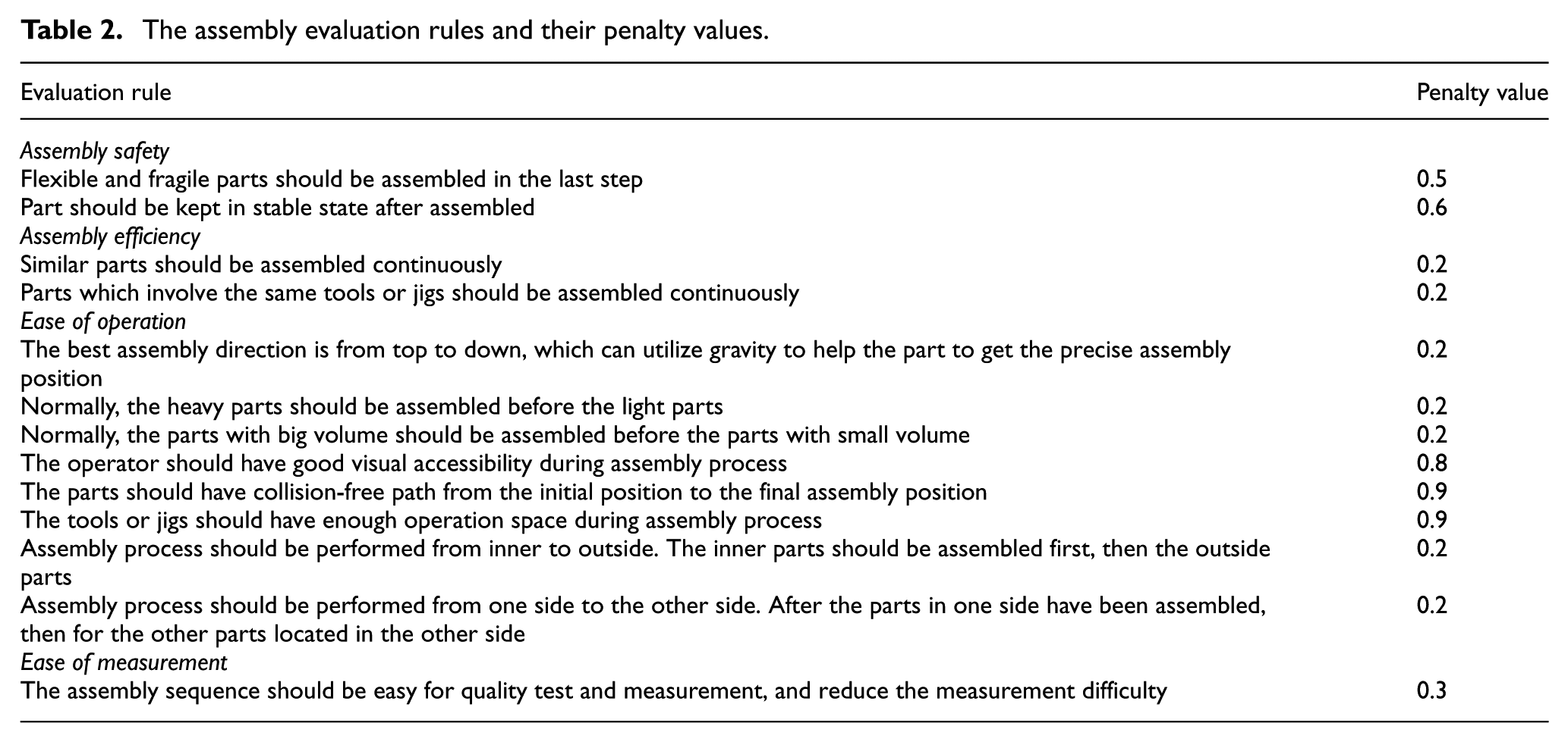
VR and haptics provide an efficient approach to help the users to exert their assembly-related experience and knowledge. Because the virtual assembly environment is realistic and natural as the real assembly process, the user can easily recognize the new precedence constraints and evaluation rules according to assembly operation space, assembly tool simulation, human vision accessibility, ergonomics and safety, and so on. A simple knowledge base system can be developed to manage the assembly evaluation rules and their penalty values. For different products, the general evaluation rules can be retrieved from the knowledge base first, and then after edit and optimization, the best evaluation rules can be obtained.
Example
A haptics-based intelligent assembly planning system has been developed with Phantom Premium for 6-DOF haptic feedback and a virtual hand model for visual realism. A pump in a complex aerospace product is chosen as an example to demonstrate the proposed method. The CAD model of the aerospace product is shown in Figure 6, the mechanical structure of the pump and its components are shown in Figure 7 and Table 3. After data transformation from CAD to VR, a constraint-based virtual assembly environment can be reconstructed. 9 Haptics-based assembly process simulation can be realized as shown in Figure 8. When the operated part is close to the assembling part, a hybrid approach based on geometry constraint and physics modeling will be activated, which can help the part to get the final precise assembly position. Haptics-based assembly tool simulation can also be realized as shown in Figures 9 and 10.

CAD model of the aerospace product in pro/engineering.
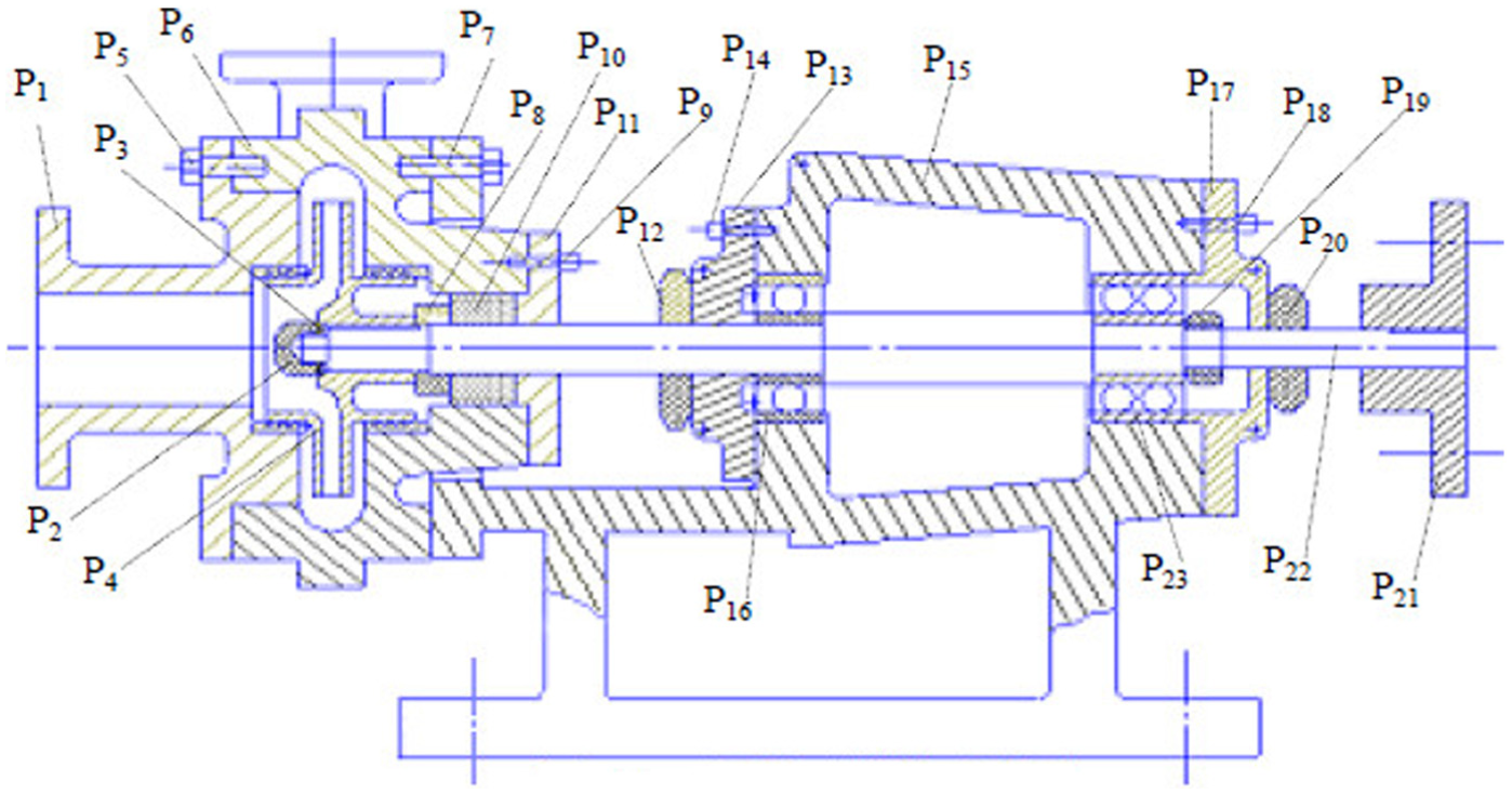
The mechanical structure of a pump.
Part list for the pump.


Haptics-based part assembly simulation.

Haptics-based tool operation simulation for the screwdriver.

Haptics-based tool operation simulation for the wrench.
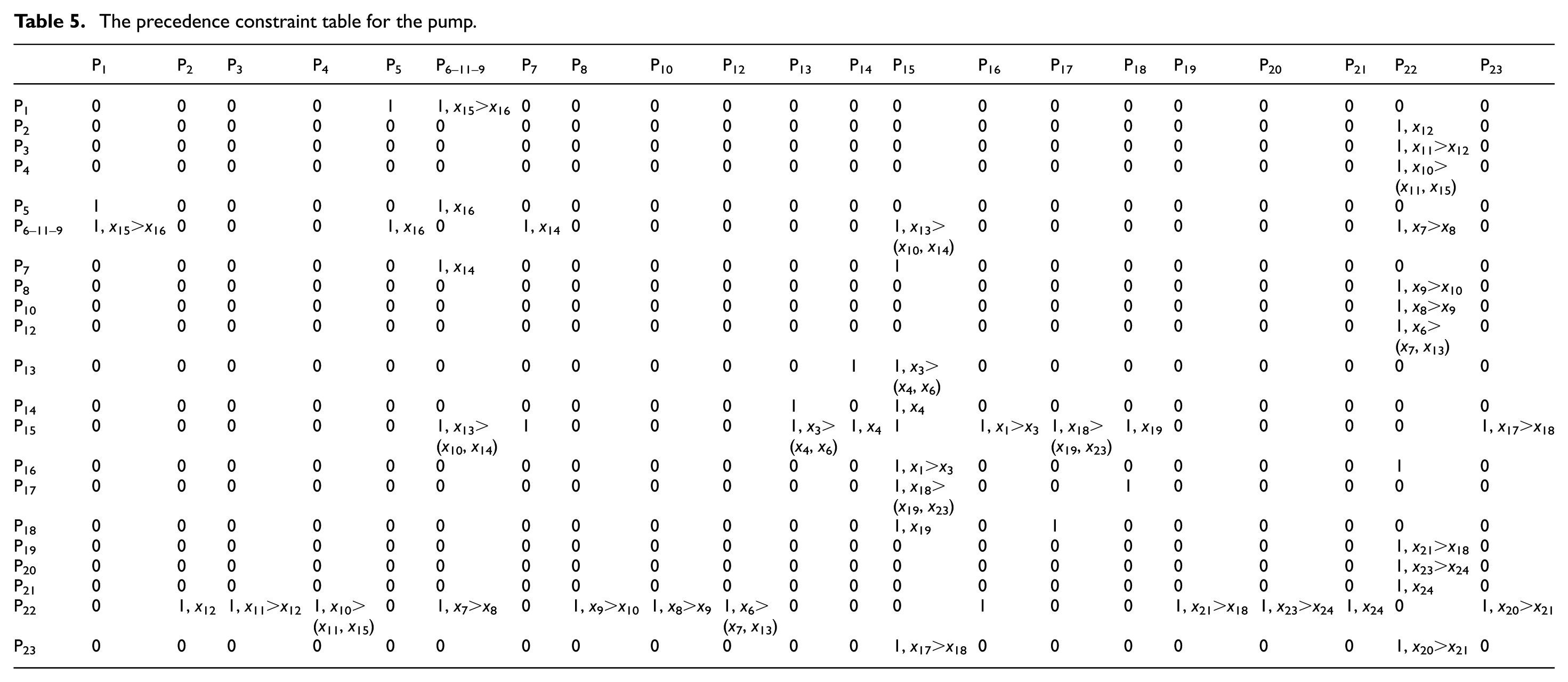
Haptics can improve assembly task efficiency by reducing task completion time. As the assembly task in Figure 8, the stuffing box is very difficult to be assembled to its proper position because of the narrow operation space and the blocked human vision. Five graduate students are chosen to perform the assembly task in two modes: without haptics and with haptics. After a period of practice, each student is asked to perform the assembly task five times and then the average completion time can be calculated as shown in Table 4 (for each user, the first column is the task completion time without haptics, and the second column is the task completion time with haptics). From the results, it can be seen that haptics can reduce the task completion time by 32.5%. This is because in the assembly mode without haptics, the user can only assemble the part to its final position according to geometry constraint and human vision. However, because of the vibration of human hand, it is very easy for the user to violate the geometry constraint. Also because the human vision is blocked, the user needs to try many times to assemble the part to its final position. However, in the haptics-guided assembly mode, the user can feel the collision force, the repulsive force, and the guiding force as realistic as the real world; therefore, he can assemble the part to its final position quickly and precisely, especially for the case where the vision is blocked. Haptics can also help the user to recognize new precedence constraints and evaluation rules. As shown in Figures 9 and 10, haptics provides an efficient method to drive assembly tool simulation. During assembly tool simulation, thinking about operation space, accessibility, and ergonomics, the new precedence constraints and evaluation rules will be recognized. For example, as shown in Figure 9, if P21 is assembled before P18, there is no enough operation space for the screwdriver. Similar evaluation rule can also be generated as shown in Figure 10; if P1 is assembled before P2, there is no enough operation space for the wrench. All these evaluation rules cannot be generated from CAD model by geometric reasoning, and they can only be recognized during haptics-based simulation. After several loops of simulation, the summary of precedence constraints for the pump is shown in Table 5, and the summary of evaluation rules and their penalty values is shown in Table 6, and the best assembly sequence is shown in Table 7. Here, only the final results for the best assembly sequence are given; the updating process of cost function and the iteration process of evaluation rules are not discussed.
Assembly task completion time.

The precedence constraint table for the pump.
The evaluation rules and their penalty values.

The best assembly sequence for the pump.

Comparing with genetic algorithm, the proposed intelligent assembly planning method has the following advantages: (1) genetic algorithm–based assembly planning needs the initial feasible assembly sequences as the sample, and the quality of sample has great influence on the quality of results. However, ACO-based intelligent assembly planning can generate initial optimal assembly sequences from precedence constraints and evaluation rules; therefore, the sample is not needed; (2) genetic algorithm generates new assembly sequences according to crossover and mutation operator. However, these newly generated assembly sequences may be infeasible because they will violate the precedence constraints. Therefore, genetic algorithm–based assembly planning has the problem of slow convergence. However, combining with the precedence constraint table, ACO-based assembly planning can generate more optimal assembly sequences only from the initial feasible and optimal assembly sequences. Therefore, it has a shorter convergence time and can generate better solutions.
However, the values of parameters also have important effect on the convergence of ACO algorithm. Here,
Conclusion
An efficient hybrid approach combining automatic assembly planning and interactive assembly planning is proposed in this article. The application example shows that the proposed method can improve the practicability and flexibility of assembly planning for industrial products. However, currently there are two shortcomings for the proposed method, which will be improved in the future work: (1) the evaluation rules are mainly recognized by the user during haptics-based interactive simulation, and the penalty values are mainly assigned according to human knowledge and experience. In the future, an intelligent “worker” needs to be developed to extract the precedence constraints and evaluation rules automatically from haptics-based simulation process, which can improve the intelligence of the hybrid method. (2) The knowledge base system needs to be further expanded and improved. Knowledge base provides an efficient approach for intelligent assembly planning. However, currently only a simple framework of knowledge base system is provided, more evaluation rules for different products and more penalty values for different situations are needed to supplement, and then the proposed method can be used for different industrial products.
Footnotes
Academic Editor: Xichun Luo
Declaration of conflicting interests
The author(s) declared no potential conflicts of interest with respect to the research, authorship, and/or publication of this article.
Funding
The author(s) received no financial support for the research, authorship, and/or publication of this article.