
Abstract
Torque control is usually the only method for tightening bolts in some precision assembly applications. However, the scatter of the torque–tension relationship may significantly decrease the accuracy of the preload, which conflicts with the high requirement for mechanical accuracy in such precision assemblies. An important, but often ignored, factor affecting the accuracy of the torque–tension relationship is the effective bearing contact radius. In this article, a three-dimensional finite element model of a typical bolted joint was developed to obtain the actual bearing pressure distribution, based on which the effective bearing contact radius can be further calculated. Then, a parametrical study was conducted to systematically investigate the effects of various geometrical, material, and frictional factors on the effective bearing contact radius. Based on the numerical results, a comprehensive and quantitative evaluation of the relative accuracy of each traditional method of calculating the effective bearing contact radius was made. In particular, it was found that the effective bearing contact radius, calculated based on the assumption of uniform bearing pressure distribution, was always relatively accurate regardless of the geometrical, material, and frictional conditions considered. This study will be helpful in increasing the accuracy of preload, thus ensuring mechanical accuracy and quality for precision assemblies.
Keywords
Introduction
Bolted joints are used widely in many applications due to their ease of assembly and disassembly. The safety, reliability, and quality of bolted joints are determined largely by the magnitude and stability of the clamp load or preload. To achieve a desired preload, various tightening methods have been developed, such as torque control, torque–angle control, stretch control, and yield control.
1
Among these methods, the torque control method is the most commonly used because it can be implemented readily without using complex or expensive tools. In several precision assembly applications, such as some small-batch precision optical systems,
2
the torque control method is usually the only applicable tightening method for bolted joints because of the restrictions on operating space and the limitations of assembly cost. In order to ensure the preload accuracy in precision assembly applications, the allowed percentage error of the torque–tension relationship might be as small as several percents. For example, Li et al.
2
numerically calculated the effects of preload on the deformation of a 400-mm class reflecting mirror which is a key part in a high-power solid laser facility. They found that the peak-to-valley (PV) value of the wavefront can change 2 nm when the preload changes only 1 N. For precision optical systems, the PV value is typically required to be smaller than 63 nm (i.e.
Some analytical expressions of torque–tension relationship have been developed by Motosh 3 and Nassar and Yang 4


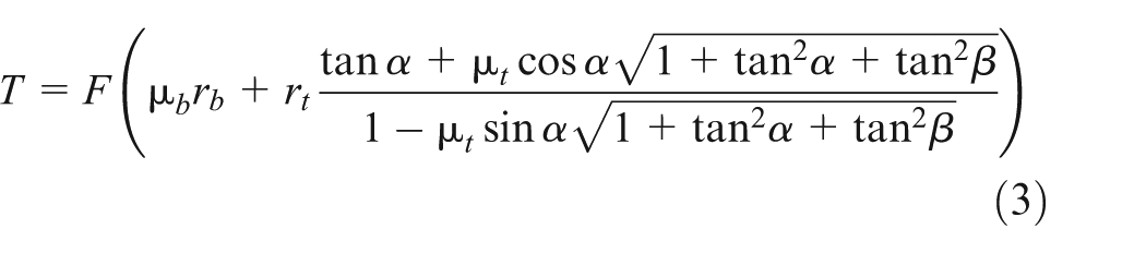
where T is the input torque, F is the preload,
It can be seen from equations (1) to (3) that the torque–tension relationship of bolted joints is determined by geometric factors (
In practice, the effective thread contact radius,
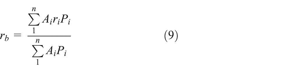
The effective bearing contact radius is defined as follows 13

where


where
Methodology
It is not trivial to accurately determine the value of
where
Specifically, a typical bolted joint structure is modeled in this study. Figure 1 shows two-dimensional (2D) sketches of the bolt, nut, and joint structures, where A=6.4mm, B=15mm, L=40mm, D = 10 mm, S=15.7mm, E=18.1 mm, M = 8 mm, and H1 = H2 = 10.5 mm. A finite element mesh was built with the commercial preprocessor HyperMesh 12.0®. Here, the mesh of the bolted joint is generated based on a strategy consistent with Fukuoka et al.’s 17 method which accurately takes into account the helical geometry and generates an orderly 3D hexahedral mesh for the bolted joint.

2D sketches of bolt, nut, and bolted joint: (a) bolt (and its bearing surface), (b) nut (and its bearing surface), and (c) bolted joint.
The mesh of the entire bolted joint is shown in Figure 2. It can be seen that the bolt head and nut are simplified to cylinders for convenience of meshing. The FEA was implemented using the commercial software ANSYS 14.5®. The mesh type is SOLID185. Young’s modulus is 200 GPa, and Poisson’s ratio is 0.3. There are four contact interfaces in this model. They are the interfaces between the mating threads, nut and upper plate, upper and lower plates, and bolt head and lower plate. A friction coefficient value of 0.15 is assigned to all sliding interfaces for the basic model. To simulate the torque control method, the target tightening torque, 80 N m, is applied directly to the upper surface of the nut using MPC184 elements, as shown in Figure 3. Other boundary conditions include the following: (1) the bolt head surface is constrained in all directions and (2) the outer surfaces of the clamped plates are constrained in the lateral direction but free to move along the bolt axis. In addition, a grid refinement study was conducted to determine the appropriate mesh density of the model.

Mesh of the entire bolted joint.

Applying tightening torque using MPC184 elements.
Results and discussions
The bearing effective contact radius is obtained based on the bearing pressure distribution. One example of the bearing pressure distribution is shown in Figure 4. In this section, the values of

Bearing pressure distribution (torque is 80 Nm, D is 10 mm, D0 is 11.2 mm, Young’s modulus is 200 GPa, and friction coefficient is 0.15).
Effect of hole clearance
To evaluate quantitatively the effect of hole clearance on the accuracy of equations (5)–(8), FEA models with three different values of hole clearance (0.225, 0.600, and 0.975 mm) were built by changing the value of D0, and the bearing pressure distribution and
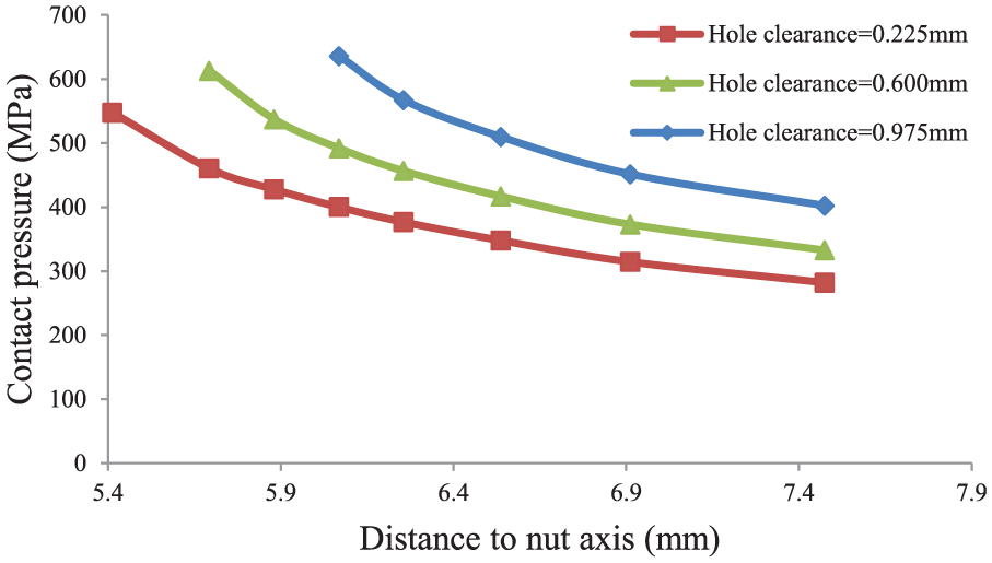
Bearing pressure distribution under different hole clearances.
Error analysis under different hole clearances.
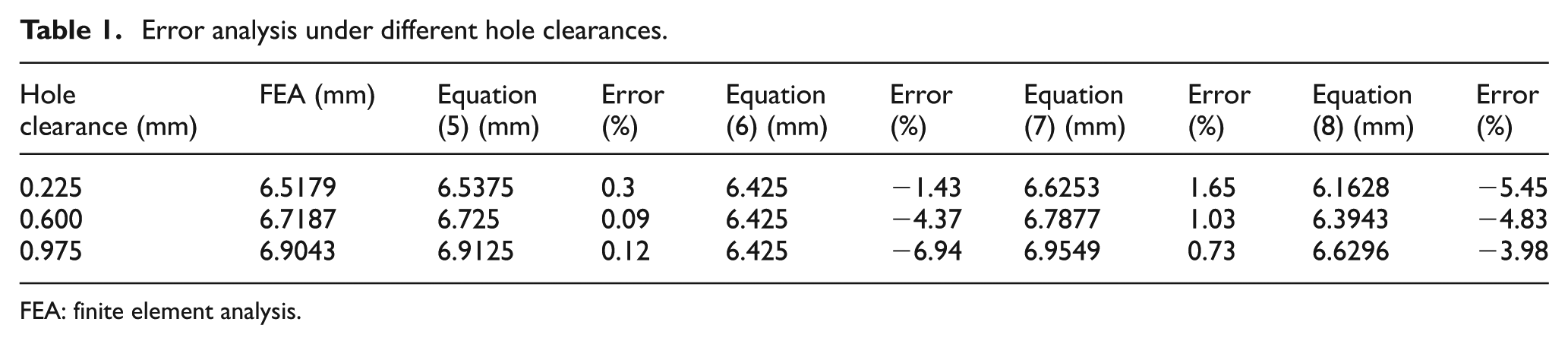
FEA: finite element analysis.
Effect of the ratio of rb–max to rb–min
The ratio of the maximum bearing radius

Bearing pressure distribution under different values of γ.
Error analysis under different ratios of rb–max to rb–min.
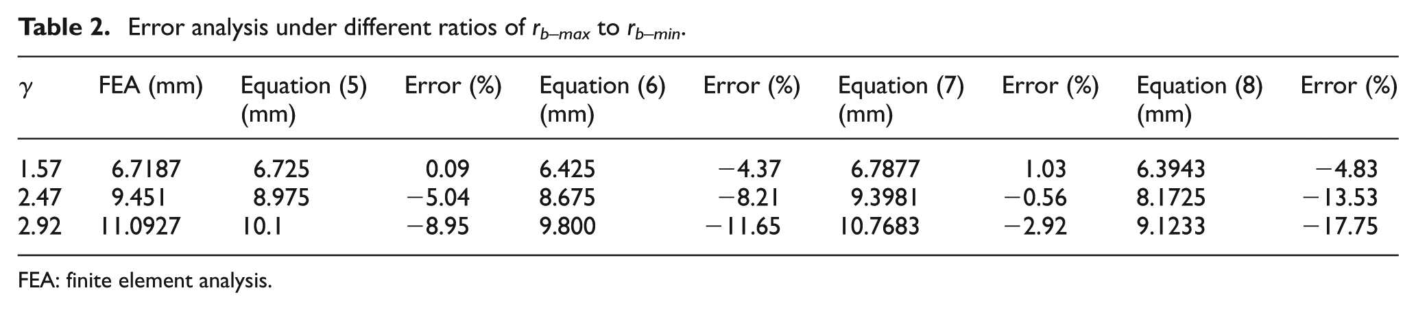
FEA: finite element analysis.
Effect of the stiffness ratio of fasteners to clamped plates
To investigate the accuracy of equations (5)–(8) under various material combinations, finite element calculations were conducted with three representative stiffness ratios (the ratio of the elastic modulus of the fasteners to the clamped plates): 2, 1, and 0.5. Specifically, the elastic modulus of fasteners was fixed at 200 GPa, while the elastic modulus of the clamped plates was varied (100, 200, and 400 GPa). The bearing pressure distribution under different stiffness ratios obtained from FEA is shown in Figure 7. Values of
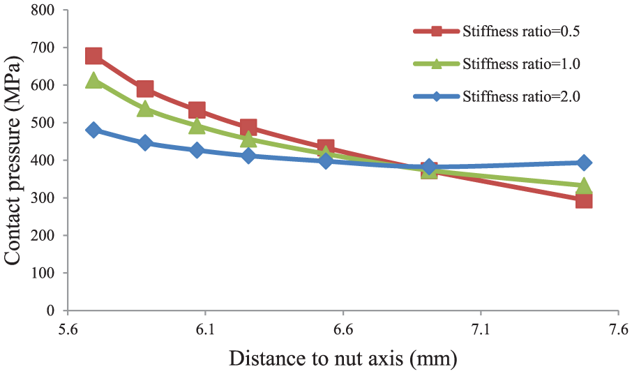
Bearing pressure distribution under various stiffness ratios.
Error analysis under different ratios of fastener to joint stiffness.

FEA: finite element analysis.
Effect of friction coefficient
To investigate the accuracy of equations (5)–(8) under various friction coefficients, finite element calculations were conducted with three representative friction coefficient values: 0.05, 0.1, and 0.15. For simplification,

Bearing pressure distribution under different friction coefficients.
Error analysis under different friction coefficients.

FEA: finite element analysis.
Validation of FEA results
The FEA model in this study accurately takes into account the helical geometry and has a high-quality 3D hexahedral mesh, with a seamless transition between the threaded section and the bolt shank. In addition, a careful mesh refinement study was done to ensure that the FEA results were grid-independent. Thus, it would be expected that the FEA results and corresponding conclusions obtained in this study are accurate. In this section, the accuracy of the FEA model is further validated by comparing the torque–tension relationship extracted directly from the FEA model with equation (3), which is the most accurate analytical torque–tension relationship to date. The results are shown in Figure 9. All geometric, material, and boundary conditions in the calculation are the same as the basic model, discussed in section “Methodology.” The

Comparison of the torque–tension relationship obtained from FEA and equation (3).
It can be seen that the torque–tension relationship from the FEA model is almost the same as that calculated based on equation (3). The relative error between these two sets of results is smaller than 0.5%. Given that these two sets of results are obtained using completely different strategies (numerical calculation and analytical derivation), the consistency of the results can be considered an evidence of the accuracy of both models (FEA model and analytical expression).
Conclusion
In this article, a 3D hexahedral finite element model of a typical bolted joint was built, based on which the tightening process of the bolt was simulated, and the actual bearing pressure distribution was calculated. Then, the effective bearing contact radius, based on the FEA results of bearing pressure distribution, was obtained. The relative accuracy of various methods of calculating the effective bearing contact radius was analyzed systematically and compared. The effects of the hole clearance, the ratio of the maximum to minimum bearing radius
It was found that the effective bearing contact radius calculated based on the assumption of uniform bearing pressure distribution (equation (7)) was always relatively accurate for the conditions considered in this study. The relative error of equation (7) was generally less than 2%. The mean bearing radius (equation (5)) can accurately evaluate the effective bearing contact radius when
In conclusion, if the ratio of the maximum to minimum bearing radius is relatively small (less than 2, based on the results of this study), both equations (5) and (7) can satisfy the requirements for precision assembly applications. Otherwise, only equation (7) should be used in precision assembly applications. Considering that the allowed error of the torque–tension relationship might be as small as several percents for precision assembly applications, equations (6) and (8) are not suitable for these applications. The results and conclusions of this study can help to increase the accuracy of the torque–tension relationship for tightening bolted joints, thus ensuring mechanical accuracy and quality for precision assemblies.
Footnotes
Appendix 1
Academic Editor: Filippo Berto
Declaration of conflicting interests
The author(s) declared no potential conflicts of interest with respect to the research, authorship, and/or publication of this article.
Funding
The author(s) disclosed receipt of the following financial support for the research, authorship, and/or publication of this article: This research was supported by the National Natural Science Foundation of China (grant no. 51675050 and 51605030).