
Abstract
Bucket elevators are efficient machines to transport the granular materials in the vertical direction or along the inclined planes. Traditional bucket elevators have strong limitations in the discharging position and discharging mode. So it has important practical significance to design and develop a chain bucket elevator with multipoint discharge which can realize the horizontal and vertical simultaneous continuous transportation. The bucket is the load bearing component of the bucket elevators. This article presents the method of solving the maximum contour of the bucket, which is the combination of analytic method and graphical method. The constraint conditions and the mathematical model of the interference analysis are obtained by the interference analysis at the inflection points, and the boundary contour of the bucket at the inflection points is obtained by solving the constraint equation with MATLAB. And the boundary contour of the bucket at the discharging position is obtained by the graphical method. Therefore, the maximum contour of the bucket is determined, which can ensure not only that there is no interference between the adjacent buckets in the whole process but also that the granular materials can be fully discharged and the maximum loading capacity of the buckets can be achieved.
Introduction
Bucket elevators are the common industrial devices to transport the granular materials in the vertical direction or along the inclined planes and used throughout granular materials’ handling industries, for example, food storage, processing, feed, port traffic, and other industries. The mechanical construction of a bucket elevator is a variable number of buckets attached to the conveying media (typically a fabric-reinforced belt or a chain) that transmits the motion to the buckets; McBride et al. 1 have made a complete mechanical description. Emptying the buckets can be done in two principal ways: 2 by action of gravity or by centrifugal force.
In modern enterprises, a complete conveying system often contains a variety of conveying equipments. It is generally realized that the material is transported in the horizontal direction by the belt conveyor or the scraper conveyor,3–5 and by bucket elevator achieve material conveying in the vertical direction. Therefore, a traditional material conveying system contains a variety of mechanical equipments, and the position of conveying equipment is fixed, which cannot meet the complex and changeable working condition requirements. If a complete conveying system contains more conveying equipments, conveying efficiency becomes lower, energy consumption will be greater, environmental performance is worse, and the failure rate becomes higher. What is more, the collision will occur in the entire conveying system, if one link failure occurs. These are the disadvantages of the traditional conveying system. For example, the vertical bucket elevators convey materials only in the vertical direction.
The design and performance of the elevators vary with the characteristics of the material and must at least consider the geometry of the bucket and the operational speed. 6 The conveyed granular materials might be quite different, for example, granulates, grains, or pellets. There are different designs of bucket elevators: AUMUND belt bucket elevators had achieved conveying capacities of up to 1500 t/h, conveying heights of up to 160 m. 7 A BEUMER belt bucket elevator transports cement in Bhatapara, India, with a bucket width of 1.25 m, conveying heights of up to 158 m, and conveying capacity of up to 650 tons/h. 8
Although these bucket elevators had achieved large conveying capacities and heights, they still have strong limitations in the discharging position and discharging mode. So it has important practical significance to design and develop a chain bucket elevator with multipoint discharge which can realize the horizontal and vertical simultaneous continuous transportation. This article presents a method for solving the maximum contour of the bucket for a chain bucket elevator.
Description of kinematics
The schematic diagram of the chain bucket elevator with multipoint discharge is shown in Figure 1. The granular material is charged in the bottom horizontal section. The discharge of the granular material from the buckets through the turnover mechanisms is set in the upper horizontal section. In addition, the buckets flipped through the turnover mechanisms at the discharging positions, and it always ensures the feed inlet of the buckets upward under the influence of gravity in the rest of working stroke. So the filling of the bucket occurs in the lower horizontal section. The discharging point is set at the upper horizontal section through the turnover mechanisms, and the drive motor is set at inflection point 3.

Schematic diagram of the bucket elevator.
The bucket is the load bearing component of the bucket elevator, and the shape of the bucket is closely related to the efficiency of the bucket elevator. There is no interference between the adjacent buckets at the six inflection points, and when discharging, the interface will also not occur. What is more, the material can be fully discharged. The buckets and the chain are hinged through a long pin shaft, and the layout of the bucket and the chain link is one to one. Before the interference analysis, in order to ensure the maximum loading capacity of the bucket, the cross-sectional size of the bucket in the horizontal direction, that is, the chain pitch (p), is from the maximum size of the horizontal direction, and the contours on both the sides of the bucket are designed as circular arc, as shown in Figure 2. In Figure 2, r is the radius of the contour on both the sides of the bucket, and A, B, and C are the endpoints of the section contour of the bucket. This article presents the method of solving the maximum contour of the bucket through the interference analysis at the inflection points and the discharging position.

Cross section of the bucket.
The relationship of the position between the adjacent buckets at the inflection points is shown in Figure 3. In Figure 3, 1, 2, 3, 4, 5, and 6 are the six inflection points during a complete cycle; O1 and O2 are the rotation centers of the adjacent buckets, and the values of x and y are the relative coordinates of O1. Bucket 1 rotates a circle with respect to bucket 2 after a conveying cycle. At the inflection points, the movement style of the chain link is the planar motion and the bucket is the translational motion. If the interference occurs in the process, it can only be caused by the rotation of the chain link. According to the theories of kinematics, inflection point 2, inflection point 3, and the lower part of inflection point 4 have the same or opposite motion relationship as can be seen from Figure 3, so their constrained conditions are same. The upper part of inflection point 1 and inflection points 5 and 6 have the same or opposite motion relationship, so they have the same constrained equations. As the schematic diagram shown in Figure 1, the kinematic relationship of inflection points 2 and 6 and inflection points 3 and 5 is inverse. As described above, when analyzing the inflection point, the boundary contour of the left side of the bucket can be determined from the inflection point. The boundary contour of the right side of the bucket can be determined by the lower part of inflection point 1 and inflection point 4.

Relationship of the position between the adjacent buckets.
Interference analysis at the inflection points
Interference analysis at inflection point 2
As shown in Figure 4, inflection point 2 is a transitional position from a horizontal stroke to a vertical stroke. If interference occurs in the process, it can only be that vertex B2 of bucket 2 interferes with the A1C1 arc edge of bucket 1. So when the length of B2D is greater than 0, the interference does not occur. If the B2D is 0 or less, there would be collision between the buckets. It can be transformed into a mathematical model, that is

where O1 and O2 are the centers of the circles A1C1 and A2C2, respectively, and Δl is the variation in the distance between the adjacent buckets 1 and 2 in the horizontal direction, and Δh is the variation in the distance between the adjacent buckets 1 and 2 in height.

Motion diagram at inflection point 2.
When entering into arc segment at a time t = 0, bucket 1 does translation motion. When entering into arc segment at a time t = p/v, bucket 2 does translation motion. p is the chain pitch, and v is the bucket velocity. With the increase in time, the horizontal distance between the adjacent buckets decreases, but the vertical direction distance increases.
The establishment of the coordinate system is shown in Figure 2. When
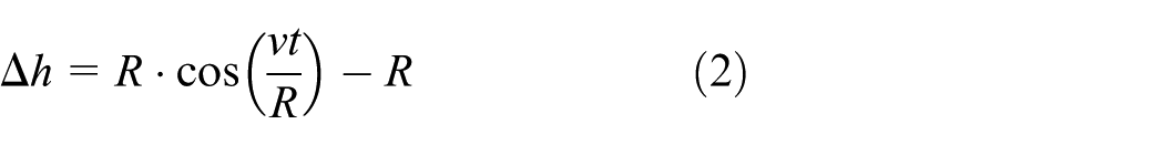
where R is the radius of the sprocket pitch circle. The variation in the distance between the adjacent buckets 1 and 2 in the horizontal direction is

When

and the variation in the distance in the horizontal direction is

The parameter equations of


In the parametric equations, the pitch of the chain (p) is 200 mm, the radius of the sprocket pitch circle (R) is 417.5 mm, and the bucket velocity (v) is 500 mm/s. The functional graph of Δh and Δl (as shown in Figure 5) is calculated by the above parameters into equations (6) and (7) by means of MATLAB.

Functional graph of
According to the theories of the planar motion, the curve is the trajectories of point B2 of bucket 2 with respect to bucket 1. Point B1 is taken as the center of the arc, and the length of the chain pitch (p) is taken as the radius of the arc. There is no interference if the contour on the left side of the bucket is on the right side of the curve, so the boundary contour of the left side of the bucket is an arc with a radius (r) of 200 mm.
Interference analysis at inflection point 4
As shown in Figure 6, the upper part at inflection point 4 is the transition from a vertical stroke to a horizontal stroke. If interference occurs, it can only be that vertex A2 of bucket 2 interferes with the B1C1 arc edge of bucket 1. So when the length of A2D is greater than 0, the interference does not occur. If the A2D is 0 or less, there would be collision between the buckets. It can be transformed into a mathematical model, that is


Motion diagram of inflection point 4.
The establishment of the coordinate system is shown in Figure 6. When the two buckets are arranged in a vertical alignment, the time (t) is set to 0. At time t, the variation in the horizontal distance between the buckets is

where R is the radius of the sprocket pitch circle. The variation in the vertical distance is

The parameter equations of

The functional graph of Δh and Δl is calculated by the above parameters into equation (11) by means of MATLAB, as shown in Figure 7.

Functional graph of
According to the theories of the planar motion, the curve is the trajectories of point A2 of bucket 2 with respect to bucket 1. Point A1 is taken as the center of the arc, and the chain pitch (p) is taken as the radius of the arc. There is no interference if the contour on the right side of the bucket is on the left side of the curve, so the boundary contour of the right side of the bucket is an arc with a radius of the contour on both the sides of the bucket (r) of 200 mm.
The boundary contour of the bucket can be drawn through the boundary contour of Figures 4 and 6 on both the sides of the bucket, as shown in Figure 8. The horizontal size is the chain pitch (p), respectively, the contours on both the sides are the arc, of which the horizontal endpoint is taken as the center and the chain pitch is taken as the radius.
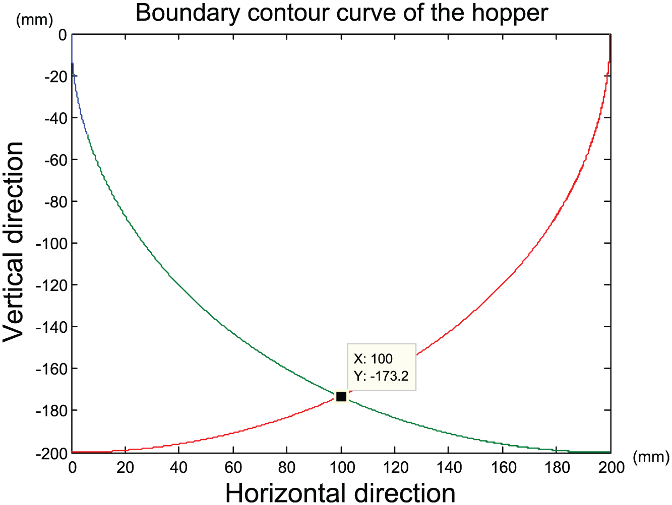
Boundary contour of the bucket.
Interference analysis at the discharging position
Through the interference analysis at the inflection points, the boundary contour of the bucket, where there is no interference at the inflection points, is an arc whose radius is the chain pith. The external friction angle between the material and the steel plate is 30° 9 when the material is discharged smoothly, and the turnover mechanism makes the bucket flip 85°. So the contour on the discharging side of the bucket designed into 55° with the horizontal direction.
At the flip discharging position, the latter bucket already starts to flip when the former bucket has not returned to the initial position. Therefore, it is necessary to ensure that the adjacent buckets will not interfere in the process of discharging. As shown in Figure 9, the right side of bucket 1 flips downward in the solid circular arc, the center of which is point O1, and the radius of which is the distance between point O1 and point B1. There is no interference if the left side of bucket 2 flips upward in the dotted circular arc. It can be transformed into a mathematical model, that is

where R1 is the radius of right contour of the bucket and R2 is the radius of left contour of the bucket.

Limiting contour of the bucket.
The maximum contour of the bucket is finally determined by the interference analysis at the inflection points and the discharging position, as the heavy lines shown in Figure 9.
Conclusion
The constraint conditions of the interference between the buckets are obtained through the interference analysis at the inflection points of the chain bucket elevator with multipoint discharge, and the boundary contour is obtained by MATLAB. The boundary contour of the bucket at the discharging position, where the interference does not occur at the discharging process, is obtained by the graphical method. Through considering the turning angle at the discharging position and the external friction angle between the material and the steel plate, ultimately the maximum contour of the bucket is determined. It can ensure not only that the interference does not occur in the whole process but also that the granular materials can be fully discharged and the maximum loading capacity can ensure the efficiency of the bucket elevator.
Footnotes
Appendix 1
Academic Editor: Liyuan Sheng
Declaration of conflicting interests
The author(s) declared no potential conflicts of interest with respect to the research, authorship, and/or publication of this article.
Funding
The author(s) disclosed receipt of the following financial support for the research, authorship, and/or publication of this article: This work was supported by the Hubei Yidu Yiyun Mec & Elec Engineering Co., Ltd.