
Abstract
It has been widely investigated before that both heavy rain and icing conditions can cause severe aerodynamic performance penalties to aircraft in flight; however, aircraft aerodynamics in the presence of both heavy rain and ice accretion has been little explored so far. In this article, a numerical simulation is performed to study the aerodynamic performance of an iced NACA 0012 airfoil in simulated heavy rain condition. A two-way momentum-coupled Eulerian–Lagrangian two-phase flow approach is developed to simulate raindrop trajectories in the airflow field. The analysis indicates that both rain and ice can separately cause severe aerodynamic performance degradation to the airfoil at most angles of attack of interest. In the presence of both ice and rain, a further severe aerodynamic penalty can be produced by rain based on the ice-induced aerodynamic performance degradation. Premature boundary-layer separation and boundary-layer momentum losses by splashed-back raindrops are also observed.
Keywords
Introduction
Aircraft performance degradation due to flying in adverse weather conditions remains a constant concern within the aviation community. Herein, two factors, that is, heavy rain and icing, have attracted particular attention due to their undetermined detrimental effects on aircraft aerodynamic performance.1–3 Although there have been many research achievements on the effects of icing4–6 and heavy rain7–9 on aircraft aerodynamic characteristics, none is found to consider the coupling effects of the two. However, a situation that an aircraft with an initial leading-edge ice accretion is flying through a cumulonimbus cloud or rain condition actually exists, especially in the Northeastern America where the weather is always cold and sometimes with rainfall in winter. Additionally, aircraft icing also occurs in freezing drizzle or rainfall where the coupling effects of rain and icing exist. Thus, it is necessary and significant to study the coupling effects of rainfall and ice accretion on aircraft aerodynamics.
In this article, a two-way-momentum-coupled Eulerian–Lagrangian two-phase flow approach is adopted to study the aerodynamic characteristics of a NACA 0012 airfoil with post-leading-edge ice accretion in a simulated heavy rain encounter on the basis of our earlier work. 9 Regarding the improvement of the previous method, the dispersion of particles due to turbulence in the continuous phase is taken into consideration in this study by incorporating a random walk dispersion model. Both the individual and coupling effects of heavy rain and ice accretion on the aerodynamic performance of the airfoil are investigated. Considering the fact that there is no open report on the current topic, our study can provide a new insight into the effects of the two common adverse weather factors on aircraft aerodynamics.
Methodology description
Continuous phase
The steady-state incompressible Reynolds-averaged Navier–Stokes equations of mass, momentum, and energy are solved for the airflow field. The pressure-based segregated SIMPLE algorithm is adopted for pressure–velocity coupling calculation. The convection terms were discretized using the second-order central scheme, while the viscous terms using the QUICK scheme. 10 The viscous coefficients were solved by associating with the S–A turbulence model. The governing equations for the airflow field are written as follows


where
The conversation equations for the momentum and turbulence after discretization at a certain cell “C” can be generally written as

where
The total residual

The convergence criteria for our calculation are the residuals of the continuity, momentum, and turbulence equations which are reduced by five orders of magnitude relative to the initial residuals. For the momentum and turbulence equations, that is

where

where
Discrete phase
Raindrop tracking algorithm
The raindrops in our study are assumed to be non-interacting, non-deforming, and non-evaporating spheres only subject to drag and gravity forces. For raindrops whose density is much greater than air density, the dimensional equations of motion for a particle can be written as


where

The drag coefficient

In this work, the second-order accurate implicit trapezoidal discretization is adopted to solve equations (7) and (8). The final iterative formulas are given as follows

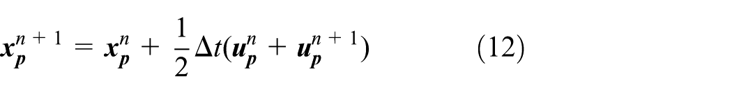
where the superscript “n” denotes the current time step and “n + 1” the next time step.
Random walk dispersion model
In this study, the dispersion of raindrop particles due to turbulence in the air phase is taken into consideration. In equation (7), the air velocity can be represented as


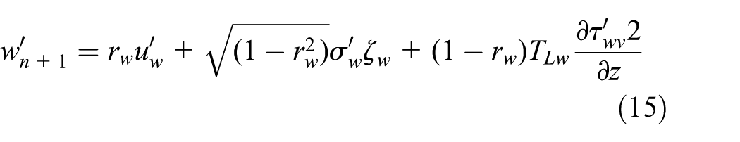
where

where s denotes the particle path.
Water film model
To simulate the interaction between raindrop and airfoil wall surface, the water film model in Stanton and Rutland 14 is adopted in our study, which allows a single-component liquid drop to impinge upon a surface of arbitrary configurations and form a thin water film. The main physical processes that affect the liquid film are shown in Figure 1(a). The governing equations for water film can be referred to in our previous work. 9

(a) Mechanisms of mass, momentum, and energy transfers for the thin water film and (b) the four impingement regimes included in the film model. 14
In our work, we do not consider the energy issue, since the current flight is a low-speed movement (130 mile/h, about 58 m/s). With regard to this, convective heat transfer from water film to air, heat conduction from wall to water film and raindrop evaporation are not considered. There are four regimes for determining the different interactions between raindrop and wall, including stick, rebound, spread, and splash, as shown in Figure 1(b). The criteria by which the regimes are partitioned are based on the raindrops’ Weber number defined by

where
The stick regime occurs when an impinging drop with extremely low impact energy adheres to the film surface in, approximately, a spherical form and is triggered at
Range of the raindrops’ Weber number characterizing the four regimes for this study.

Interphase coupling
In our study, a two-way momentum coupling process is used to account for the interphase interaction between the air and raindrop phases. The momentum transfer from air to raindrop acts as a momentum sink in the air-phase momentum balance in the subsequent solution for the airflow field. It originates from the interphase drag and is explicitly accounted for in the Lagrangian particle trajectory (equation (7)), which is expressed as
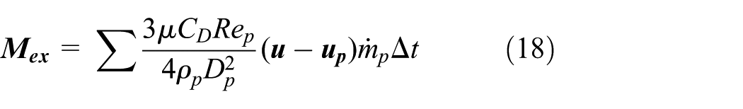
where
Calculation process
In the process of rain simulation, first, the dry airflow field is calculated. Then, the raindrop trajectory is calculated based on the obtained air velocity field. Afterward, the momentum coupling “body force” term calculated by equation (18) is added to the source term of the air momentum equation to account for the raindrop effect on the air phase. So far, a loop of calculation is completed. This loop is repeated until both the air and raindrop phases reach a steady state, as shown in Figure 2. The convergence criteria for our calculation are as follows: first, the residuals of the continuity, momentum, and turbulence equations of the continuous phase are reduced by five orders of magnitude relative to the initial residuals, which denotes the convergence of the air phase; and second, the final results of lift and drag coefficients were independent of the raindrop number in the model; that is, further increase in particle number in the simulation did not remarkably affect the final results, which is deemed as the equilibrium of the raindrop flowfield, since raindrops are ejected from the upstream side and exit from the downstream outlet.

Flowchart of the calculation process.
Results and discussions
The first step in our study is the modeling of the ice shapes obtained in the Ohio State University subsonic wind tunnel. 15 In this study, the No. 2 NACA 0012 airfoil is adopted because of its available geometry and experimental aerodynamic data from the experiment. The airfoil chord length is 0.5334 m. The icing conditions that produced this ice shape are angle of attack of 4°, free-stream velocity of 58 m/s (corresponding to Reynolds number of 1.5 × 10⁶), median volume diameter of 20 µm, liquid water content (LWC) of 2.1 g/m3, total temperature of 265 K, and 5 min spray time.
The two-dimensional (2D) grids are used in our study for modeling the computational region around the clean and iced airfoils consisting of two blocks, where the inner and outer blocks have an overlapping interface at 0.6 c, as shown in Figure 3. Both blocks have a C-type structured grid, while the inner one has a wake cut downstream of the trailing edge and a much denser distribution of grid points than the outer block. Both blocks have a boundary at 10-c upstream and 15-c downstream from the leading edge. This mesh strategy of constructing two-block grids not only allows for easier control of the grid generation process and better quality of the resulting grid, especially near the complex iced surfaces, but also reduces the mesh size of the region far from the airfoil surface which is not necessarily large for a high equality of acquired flowfield simulation, thus saves much computational resource.
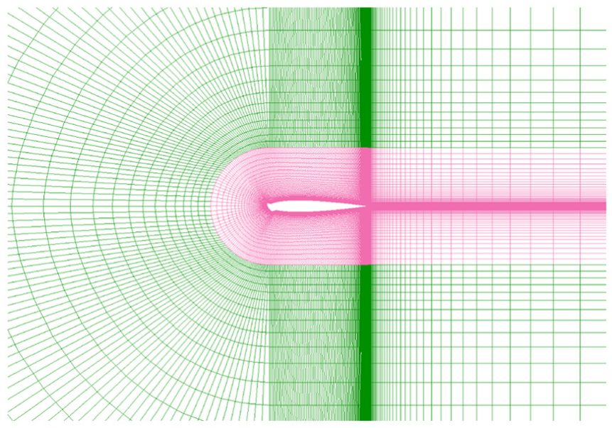
Two-block grid strategy.
Grid independence of the solutions is assessed by constructing a new grid with additional refinement for the clean airfoil configuration. As shown in Figure 4, the simulated lift coefficient CL obtained from the clean airfoil grid resolution with a total of 340 nodes on the surface of the airfoil and 80 nodes in the normal direction of the inner block, with a first layer thickness of 2.0 × 10⁻⁵ c, guarantees a grid-independent solution for, as an 18% and 25% refinement in the streamwise and normal directions, respectively, changing the results by less than 1%. Besides, the simulated results from this grid solution shows a maximum error of only about 1.72% compared to the wind tunnel experimental results. 15

Grid sensitivity test in the normal direction: lift.
For rain simulations, a heavy rain condition of LWC of 30 g/m3, free-stream velocity of 58 m/s (corresponding to Reynolds number of 1.5 × 10⁶), and a range of raindrop diameter from 0.1 to 0.9 mm which is equivalent to an arithmetic mean diameter of 0.4672 mm are selected in this study.
Figure 5(a) and (b) presents the numerical results of lift and drag coefficients for the airfoil in the four cases (i.e. clean airfoil in dry air, clean airfoil in rain, iced airfoil in dry air, and iced airfoil in rain). On one hand, both the heavy rain and the ice bring significant aerodynamic performance degradations to the clean airfoil, although it can be seen that ice induces a heavier aerodynamic penalty than heavy rain due to a very severe glazed ice accretion selected. Thus, an adverse effect of heavy rain equivalent to that of icing can be expected, if a lighter icing condition is encountered. On the other hand, rain brings a further consistent decrease in lift as well as increase in drag to the iced airfoil at angles of attack below 9°, although no significant changes occurred at higher angles of attack. Regarding the effect of rain, a maximum percentage decrease in CL by 24% and 7% and increase in CD up to 108% and 6% are caused by rain for the clean and iced airfoils, respectively. Considering aircrafts’ cruise (usually at 0°–2°), take off, and landing (usually at 4°–8°) at low angles of attack, these findings can be of much importance to guide both engineering design and pilot flight training.

(a) Lift comparison for iced airfoil in rain and (b) drag comparison for iced airfoil in rain.
Previous studies have found that rain can cause premature separations to airfoil boundary layer.8,9 The streamlines around both the clean and iced NACA 0012 configurations in the dry and heavy rain conditions at α = 12° are presented through Figure 6(a)–(d). From Figure 6(a), it can be seen that there is little airflow separation near the trailing edge of the clean configuration. However, clear separation can be seen for the clean configuration in the heavy rain condition at the same angle of attack in Figure 6(b), suggesting a premature boundary-layer separation induced by heavy rain to this airfoil. Besides, the leading-edge ice shape causes more severe boundary-layer separation in a large region over the trailing edge, as shown in Figure 6(c). It can be seen from Figure 6(d) that heavy rain causes a larger separation zone above the trailing edge of the iced airfoil, making it more severe. To quantify the effect of rain on the separation characteristics, a plot of the shear stress along the horizontal direction, x-shear stress, as a function of the normalized chord position for the upper wall of the airfoil is presented in Figure 7. For the clean configuration in dry condition, no significant separation can be quantified. While in rain, a clean separation emerges with a separation point starting at about 80% chord. For the iced configuration, rain does not bring any advance in the separation point, since ice has caused a full separation on the whole chord of the upper airfoil wall. Despite that it can be seen that there exists a small decrease in the magnitude of the shear stress at the leading edge and the front of the airfoil, indicating a decreased friction drag for the iced airfoil in rain. It further suggests that the boundary-layer velocity of the iced airfoil is decelerated by the splashback of raindrop at this time, since friction drag is reduced with decreasing boundary-layer air velocity, which will be presented more in detail in the next discussion.

Streamlines around the clean airfoil (a) in dry air at α = 12° and (b) in the rain condition at α = 12°. Streamlines around the iced airfoil (c) in dry air at α = 12° and (d) in the rain condition at α = 12°.
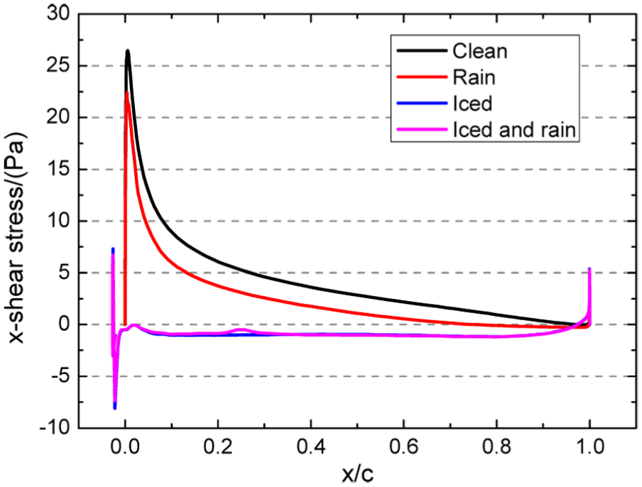
x-shear stress on the upper wall of the airfoil.
As raindrops strike on the airfoil surface, some of them are splashed back and break up into secondary drops. The acceleration of these splashed-back droplets by the airflow field acts as a momentum sink for the boundary layer, resulting in a decrease in the air velocity field. De-energization of the boundary layer can induce a loss of lift and L/D, increase in drag, premature stall, transition and separation. 9 Figure 8 shows the boundary-layer velocity profiles at four chordwise positions on the upper surface of the iced airfoil in the heavy rain condition at α = 6°. Near the leading edge, more severe deceleration of the boundary layer by splashed-back raindrops relative to the boundary without rain can be seen. Moving downstream, the boundary layer appears to recover.

Boundary-layer velocity profiles at four chordwise positions on the upper surface of the iced airfoil at α = 6°. Position is measured from the leading edge. Dimensionless velocity
Conclusion
In this article, a post-ice-accretion computational fluid dynamics (CFD) numerical simulation is performed on the aerodynamic performance of an iced NACA 0012 airfoil under a simulated heavy rain condition. This study is conducted to obtain some quantitative data of the coupling effects of heavy rain and ice accretion on airfoil aerodynamics and to provide a new insight into the aerodynamic penalties caused by such two adverse weather conditions as icing and heavy rain that may lead to a control upset. Aerodynamic performance degradations were observed for the clean airfoil in the conditions of heavy rain and ice accretion. Heavy rain can cause premature boundary-layer separation to both the clean and iced airfoils. Boundary-layer momentum losses by splashed-back raindrops were also observed on the iced NACA 0012 airfoil, which is a typical consequence of the adverse effects of rain imparting airfoils/wings. As the requirement for commuting airplanes is rising, our study can be significant for future design of commuting airplanes and pilot training to safely fly in such adverse weather conditions of icing and heavy rain.
Footnotes
Appendix 1
Academic Editor: Roslinda Nazar
Declaration of conflicting interests
The author(s) declared no potential conflicts of interest with respect to the research, authorship, and/or publication of this article.
Funding
The author(s) received no financial support for the research, authorship, and/or publication of this article.