
Abstract
Tool geometry has a significant influence on cutting force, cutting temperature, and surface quality. Restricted contact tools show good advantages in reducing cutting force, decreasing temperature, and improving surface quality. In this article, a new pattern of chip curl, “chip inward curl,” and its influence on dimensional accuracy were investigated using a novel restricted contact tool when cutting grooves. This novel restricted contact tool has symmetrical tool/chip contact length which varies along the main cutting edge and has a smaller tool land length in the middle of the rake face. In order to analyze the chip inward curl and its influence on dimensional accuracy with this novel restricted contact tool, a theoretical method to predict the chip back-flow angle using a slip-line model taking into consideration of cutting tool edge was proposed. Dimensional accuracy of the grooves achieved by this novel restricted contact tool in groove cutting tests was investigated and compared with those cut by a conventional flat-faced tool. Also, three-dimensional finite element models were developed to analyze the chip back-flow angle and chip inward curl. Results indicate that this new type of restricted contact tool has significant advantages in the control of chip curl and obtains better dimensional accuracy in groove cutting.
Introduction
Chip control is one of the most important aspects in researching the metal cutting process. Efficient chip control in metal machining greatly contributes to the production of high-quality products both in dimensional accuracy and surface roughness and therefore increasing productivity and prolonging tool life.
The control of the chip form is one of the main points of chip control. There are two basic chip forms that have been widely recognized, namely, chip up-curl and chip side-curl. Fang 1 proposed a third basic form of chip curl which was called chip lateral curl. The type of chip formation affects the prediction of the cutting parameters such as cutting force, cutting temperature, surface quality of machined parts, and the friction between the tool and the deformed chip. There are two basic chip flow types, namely, chip side-flow and chip back-flow. The chip back-flow angle is one of the most important parameters in the analysis of chip curl and is defined as the angle between the chip flow direction and the plane perpendicular to the direction of the cutting velocity. 2 It plays an important role in the control of chip curl and chip formation, and hence, the analysis of chip back-flow angle is significant in the understanding of machining parameters in the metal cutting process.
Many previous researchers have studied chip formation characteristics in metal machining processes.3–5 Sutter and List 3 studied the morphology and chip formation mechanisms in high-speed cutting of Ti-6Al-4V titanium alloy. In their study, it was found that compared to the uncut chip thickness, the cutting speed is the most important factor in the determination of chip formation. Yang et al. 4 investigated the characterization of the chip formation in machining 1045 steel with coated carbide insert tools. They observed the chip morphology through a digital microscope and obtained the quantitative relations between the characterization parameters of chip formation and the cutting speed employed.
Among the numerous researches, different models have been adopted to study the mechanism of chip formation. Merchant 6 developed a model based on the principle of minimum energy. He suggested that plastic deformation occurs on the plane that consumes the least amount of energy. His model is a single-shear plane model and chip curl is not considered. Toropov and Ko 7 developed a unique analytical way which could predict tool/chip contact length based on a new slip-line solution. In their study, a new formula for tool/chip contact length has been obtained, and this formula shows good consistency with the experimental tool/chip contact length. Buchkremer et al. 8 proposed a three-dimensional (3D) analytic model and the relationship between chip geometry parameters and the equivalent plastic strain distribution on the free surface of chips was described. Davoudinejad et al. 9 studied the cutting forces and chip formation in dry and cryogenic cutting of Ti-6Al-4V by finite element model. The simulated chip morphology and cutting forces were compared with experimental results and were in good agreement.
It has been suggested that tool/chip contact length has significant influence on the form of chip formation. The tool land length of restricted contact (RC) tool is less than the natural tool/chip contact length and is controllable. Compared with conventional flat-faced tools, RC tools have more advantages in reducing the cutting force, decreasing cutting temperature, improving surface quality of the machined surface, and prolonging tool life. Because of these characteristics, RC tools were widely studied by a variety of researchers. Ma et al. 10 carried out finite element simulations with RC tools in dry orthogonal cutting of AISI 1045 steel. They found that RC tools could reduce the main force, thrust force, and could decrease the energy needed for machining. Arsecularatne 11 proposed a model based on cutting force with equivalent feed to predict tool life for RC tools. In his study, bar turning tests under dry conditions were carried out, and the tool life was evaluated based on flank wear. Good agreement was reached between the predicted and experimental tool life. Fang and Jawahir 12 predicted the cutting force ratio, chip thickness, and chip back-flow angle with RC tools using a universal slip-line model for RC tools and reasonable agreement was achieved. Wang and Jawahir 13 presented a model based on previously developed universal slip-line model with RC grooved tools. Four machining parameters were predicted using this model, namely, cutting forces, chip thickness ratio, chip up-curl radius, and chip back-flow angle. Moreover, this model provides a new methodology to predict the actual tool/chip interface friction and the chip-groove effects.
Previous researches on RC tools mainly focus on RC tools that have constant tool/chip RC length. Few researches on RC tools with varying tool/chip contact length have been found. In fact, these novel RC tools may have more advantages over conventional RC tools. Our previous work14,15 proposed novel RC tools with inconstant tool/chip RC length on tool rake face. It was found that novel RC tools with inconstant tool/chip RC length show better performance in the control of chip flow. Notably, these novel RC tools can decrease cutting force as well.
In this article, a kind of novel RC tool with inconstant tool/chip RC length (Figure 1) in groove cutting is investigated. As shown in Figure 1, this novel RC tool has a symmetrical inconstant tool/chip contact length which varies linearly along the main cutting edge from both sides of the main cutting edge toward the middle. Further investigation has been made in this article with this novel RC tool in groove cutting. A theoretical prediction method for chip back-flow angle with this novel RC tool is proposed using the slip-line method. Then, it is used to analyze the dimensional accuracy through the chip curl and chip formation mechanism. More complex and quantized finite element models for rectangular groove cutting based on the updated Lagrangian formulation were performed and the simulated results show reasonable consistency with the predicted values. At last, rectangular groove cutting experimental tests were conducted to investigate the chip inward curling morphology and the dimensional accuracy with this RC tool in comparison with a conventional flat-faced tool.

Novel RC tools with symmetrical inconstant tool/chip contact length.
Analysis of chip back-flow angle
Chip back-flow angle is an important parameter to analyze the condition of chip curl. In this work, a slip-line model taking into consideration of tool edge radius was developed to analyze the chip back-flow angle. According to the slip-line model, the following assumptions have been made: (1) the work material is perfectly plastic and (2) the cutting width is assumed to be much larger than the cutting depth. Therefore, the plane strain condition can be facilitated. Figure 2 shows the developed slip-line model in orthogonal cutting with the novel RC tool (Figure 1). In order to simplify the mathematical operation of this slip-line model, the effect of tool edge radius is divided into two straight boundaries AS and BS. Point S is defined as the flow-divide point of the workpiece material. Figure 2(c) shows the distribution of slip-lines and slip-line angles involved in the slip-line model in rectangular groove cutting process at face I-I. The associated hodograph at face I-I is shown in Figure 3.

Slip-line model in groove cutting with the novel restricted contact tool: (a) the 3d model, (b) the sectional view perpendicular to the cutting speed, and (c) the sectional view and distribution of slip-lines and slip-line angles at face I-I.

Hodograph of the slip-line model at face I-I.
In this slip-line model, there are a total of 19 regions in the slip-line model. The details of these slip-line fields are listed as follows:
Uniform fields with straight slip-lines. Sub-regions 1, 2, 3, 12, and 15 as shown in Figure 2(c) are uniform fields, and all slip-lines for these regions are straight lines.
Uniform fields with curved slip-lines. Sub-regions 4, 5, and 13 are also uniform fields, but the slip-lines for these regions are not all straight.
Non-uniform slip-line fields. The remaining sub-regions 6, 7, 8, 9, 10, 11, 14, 16, 17, 18, and 19 are non-uniform slip-line fields.
In Figure 2,
Figure 2(c) also shows the forces and bending moments acting on the deformed chip. It is assumed that the plane strain condition is satisfied at every section parallel to the face I-I. In order to predict the chip back-flow angle with this novel RC tool, the chip back-flow angles with certain amounts of sections which are parallel to face I-I are considered and determined. Slip-lines DGi at section i are taken as the base slip-lines. Section i is defined as the section parallel to face I-I with distance x (Figure 2(c)) equal to

where n is the total number of the computed sections.
Along the slip-lines HEi, EGi, and GDi, bending moment


For RC tools discussed in this work, the tool/chip contact length can be achieved by direct measuring. The following equation can be derived from the geometric condition of the slip-line model

where
For the novel RC tool discussed in this study, its tool land length is symmetrically varying along the main cutting edge as shown in Figure 1.
The tool/chip contact length

where α is the inclination angle of tool land length and can be determined using the following equation

Replacing α in equation (6) with equation (7) and x with equation (1), the tool/chip RC length at section i then can be represented as follows

Then, equation (5) can be expressed as

where i is the sequence number of the computed section. Here, the total number of the computed sections n is set to 9.
According to the symmetrical characteristics, the chip back-flow angles at the conditions of
Powell’s 16 algorithm for non-linear optimizations provides a viable method to solve the above equations (2)–(4) and equation (9). Finally, the theoretical equation to predict the chip back-flow angle is given as follows

where
Notably, there are constraints to an acceptable solution in the slip-line model. The hydrostatic pressure


In addition, for a reasonable solution, the material of the workpiece should be available to flow into the slip-line region 13 (Figure 2(c)). Therefore, equation (13) which provides the chip flow’s geometrical constraint should be satisfied

where
For the effect of a RC tool, the chip back-flow angle should be no less than the tool’s primary rake angle

All acceptable solutions should meet the aforementioned inequality equations (equations (11)–(14)).
Moreover, according to the hodograph in Figure 3, the following relationships can be derived


where
According to Dewhurst and Collins, 18 these factors can be represented as follows


In the above equations,
The angle

Despite the four available equations (equations (2)–(4) and (9)) derived from the forces, bending moments, and geometry conditions, there are seven unknown variables, that is,
In this work, the hydrostatic pressure
Once the maximum value of the tool land length
Finite element modeling of groove cutting with special RC tools
Rectangular groove cutting simulations are carried out based on the commercial finite element code (Scientific Forming Technologies Corporation (SFTC) Deform-3D). Several simulations are performed using the discussed novel RC tool with different tool land lengths and a conventional flat-faced groove cutter. During the simulation of the chip formation, an automatically activated remeshing procedure is used to ensure the accuracy of the data obtained from the simulation process. Therefore, the mesh of the workpiece is automatically updated during the whole simulation process.
Simulations for both flat-faced tool and novel RC tools are performed. The geometry and dimension of the RC tools employed in this simulation are shown in Figure 4. The tool edge radius for these tools is set to 0.02 mm. The geometry and dimension for flat-faced tool used in the simulation are consistent with RC tools, except that its rake face is flat without removal of tool material.

Geometry and dimension of the restricted contact tool.
The workpiece is defined as a deformable body with rigid-plastic material data. In this simulation, Al6061 is selected as the material of the workpiece. The minimum element size of the workpiece was set to 0.06 mm. About 90,000 tetrahedral elements are generated to model the workpiece, and about 40,000 elements are generated for the tool.
In the metal cutting processes, large plastic deformations take place accompanied by excessive heat generation. In this simulation, Johnson and Cook’s constitutive model for flow stress determination is adopted, and the workpiece material data are dependent on strain, strain rate, and temperature. Therefore, the flow stress of the workpiece is defined as a function concerning these factors and can be expressed as

where
A sample flow cure for the workpiece material Al6061 at 20°C, 190°C, and 345°C when the strain rate is 103 and 104 can be seen in Figure 5. The other needed flow stresses under other temperatures and strain rates are obtained by the method of interpolation and extrapolation in the simulation. During this simulation, 90% of deformation heat generation is set to be converted into heat, and the portion of frictional work being converted into heat is taken as 1.0. It is assumed that the tool/chip contact is thermally perfect, namely, a large value of 40 × 103 W/(m2 °C) is used for the interface heat transfer coefficient. As the 3d model shown in Figure 6, the surfaces CDFH, EFDB of workpiece and surfaces MNKL, MNPQ of the tool that are away from the cutting zone, and remain at the room temperature 20°C; other free surfaces on the workpiece, tool and chip, heat loss due to heat convection has taken into consideration.

Flow stress for Al6061.

Initial condition of the simulation with the restricted contact tool.
The initial position of the tool and workpiece and their mesh condition with the RC tool are also shown in Figure 6. The deformation of the cutting tools is not considered and all tools in this simulation are defined as rigid but heat transferable body. The material for the tools used in the modeling are defined as high-speed steel with a heat capacity of 1.64 N/mm2 K and thermal conductivity of 20.9 N/(s K). 19
According to studies carried out by previous researchers,20,21 there are two zones, namely, the sticking and slipping zones which show different frictional characteristics on the tool rake face. In the sticking zone, the friction coefficient changes. Therefore, the classical Coulomb friction law is not applicable in this region. While in the slipping zone, the friction coefficient is a constant and is dealt with using the classical Coulomb friction law. Therefore, the friction stress

where
A series of modeling tests with a friction coefficient varying from 0.4 to 0.9 under the same conditions were conducted in order to select an appropriate friction coefficient value. The simulated cutting forces were compared with the experimental values. Based on the results, the friction coefficient is assumed to be 0.7 in this simulation. The presented boundary conditions from this simulation are given as follows. The tool moves along the z-axis (Figure 6) with the velocity of
The measurement of chip back-flow angle

Measurement of chip back-flow angle.

The observation of the chip morphology at the cross section.
Experimental procedures
A series of comparison tests between the conventional flat-faced tool and the novel RC tool for rectangular groove cutting were carried out in this study. Both of the conventional flat-faced groove cutting tool and the novel RC tool are made of high-speed steel and have a rake angle
The workpiece used in the rectangular groove cutting tests was a cylindrical aluminum bar (Al6061) with a diameter of 46.82 mm. The chemical composition of Al6061 is shown in Table 1.
Chemical composition of Al6061.
All the cutting tests were carried out on a precision lathe (CM6140) in the absence of liquid coolant. Three factors, namely, the cutting tool used, cutting speed
Dimensions of the grooves in the direction of groove width were measured by an electronic digimatic caliper with a resolution of 0.01 mm. The accuracy of this device is ±0.03 mm. In order to observe the curling morphology of the chips, a digital microscope camera (series MD20) was used.
Results and discussion
Chip back-flow angle and chip inward curl
Chip back-flow angle is an important parameter to describe the shape of chip curl which has significant influence on the dimensional accuracy and surface quality of the machined parts. In this study, rectangular groove cutting experiments were conducted with a flat-faced tool and the novel RC groove tool. Both the tools have a tool rake angle
Figure 9 shows the comparison results of chip back-flow angles between the values obtained from the simulations using several novel RC tools with different geometry dimensions and the values predicted from the slip-line model. It can be clearly seen from Figure 9 that
Both the simulated and theoretical predicted chip back-flow angles increase from both sides of the main cutting edge to the middle with the novel RC groove tool.
Good agreement is reached between the simulated and theoretical predicted chip back-flow angles with the novel RC tool although there are some deviations when it is close to the boundary at both sides of the tool.
The chip back-flow angle only shows small changes along the main cutting edge with the flat rake face groove cutting tool. It approximately maintains the same value at different positions on the main cutting edge.

Predicted and simulated values of chip back-flow angle: (a–c) novel RC groove tool and (d) flat-faced groove tool.
As shown in Figure 9, there are some inaccuracies when using the developed slip-line model to predict the chip back-flow angle near the boundary because plane strain conditions are not satisfied near the boundary at both sides of the tool.
The shape of the chip curl can be obtained using the chip back-flow angle studied aforementioned. The chip back-flow angle could to some extent reflect the tendency of the chip curl. The increasing chip back-flow angle from both sides of the main cutting edge to the middle results in the inward curling of the chip. Therefore, when the chip flows along the tool rake face, it is in the form of spiral curling chip. Meanwhile, because of the distortion of chip, the friction between the chip and both sides of the machined groove surface decreases which is conducive to higher quality dimension accuracy of the grooves.
The simulated results show the same tendency of chip inward curling direction. Figure 10 shows the simulated morphology of the chip at the cross section parallel to the face X-O-Z (Figure 8). It can be seen that with the novel RC tool the chips curl inward from both sides of the tool toward the middle during groove cutting. With a flat-faced tool, the chip is almost flat without curling at the cross section when grooving. In addition, it was found that there is variation along the main cutting edge direction of the velocity (along the z-axis direction) at the tip of the chip due to the symmetrically varying tool land length of the novel RC groove cutting tool. As shown in Figure 11, the velocity decreases from both sides of the main cutting edge to the middle, which attributes to the inward curling of the chip in the groove cutting process with the novel RC tool.

Section morphology of simulated chips: (a) RC groove tool lmax = 0.5 mm, lmin = 0.2 mm; (b) RC groove tool lmax = 0.4 mm, lmin = 0.12 mm; (c) RC groove tool lmax = 0.6 mm, lmin = 0.3 mm and (d) flat-faced groove tool.

Simulated velocity along the z-direction and chip formation: (a) novel RC tool and (b) flat-faced tool.
Rectangular groove cutting tests with special RC tools
Rectangular groove cutting tests were conducted to verify the validity of the analysis aforementioned. The dimensional deviations at the width direction of the machined grooves were measured. The results are listed in Table 2. As shown in Table 2, higher quality dimensional accuracy was reached when grooving with the discussed novel RC tool under the same cutting conditions compared with the flat-faced groove tool.
The results of groove cutting tests.

RC: restricted contact.
Percent deviation = (mean measured value of groove width − cutting width)/mean measured value of groove width × 100%.
In order to show the influence of different cutting parameters on dimensional deviations between flat-faced and novel RC tool more clearly, the percent deviation curves along with different spindle speed and feed rate are shown in Figure 12(a) and (b), respectively. We can see clearly in Figure 12 that dimensional deviations are decreased significantly with the proposed novel RC tool. Compared with cutting speed, feed rate has more influence on the accuracy of the machined grooves since greater variation is observed in Figure 12(a). It can be seen that dimensional accuracy is improved with the increase in cutting speed. During low feed rate (0.05–0.07 mm/rev), the dimensional accuracy decreases with the increase in feed rate. However, as the feed rate gradually further increased, the accuracy increased. This is because the influence of deformation recovery becomes stronger because of the rise in cutting temperature aroused by the increasing feed rate in grooving.

The influence of cutting parameters on dimensional deviations: (a) the influence of feed rate and (b) the influence of spindle speed.
Figure 13 shows the morphology of the chips at the cross section parallel to the face X-O-Z (Figure 8). It can be clearly seen that the chips tend to curl inward with the novel RC tool, while the chips are almost straight without any curl at the section when grooving with a flat-faced groove tool.

Section morphology of chips in groove cutting with the RC tool and a flat rake face tool: (a) straight chip with flat-faced tool and (b–d) inward curl chips with the novel restricted contact tool.
The results of the rectangular groove cutting tests are consistent with the simulated results. The chip tends to curl inward due to its geometric construction design in grooving with the discussed novel RC tool, which decreases the scratching effect of the chip on the machined groove surfaces when it flows out, and because the scratching effect is decreased, better dimensional accuracy can be obtained. Moreover, because the chip curls symmetrical inward, the side-flow of the chip is decreased. This also contributes to a better dimensional accuracy of the machined groove.
Chip curl can be controlled using the RC tools by controlling the changing pattern of the inconstant tool/chip RC length. Similarly, we can deduce that other RC groove tools with a symmetrically varying tool land length shown in Figure 14 may have the same advantages in groove cutting. These tools are very practical and can be easily manufactured through the special working technology method or powder metallurgy shaping technology.
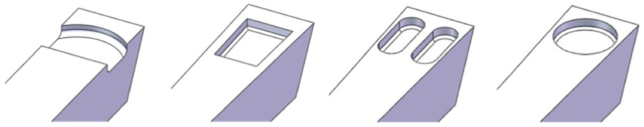
Different types of RC groove tools with symmetrical tool/chip restricted contact length.
Conclusion
In this study, the chip inward curl and dimensional accuracy in the groove cutting process with a novel RC tool were studied theoretically and by the finite element method. Cutting tests have been conducted in groove cutting with Al6061 using the novel RC groove tool and a flat-faced tool at various cutting conditions to verify the validity of dimensional accuracy and chip inward curl analysis.
The following conclusions can be drawn:
RC tools, like the RC tool discussed in this study, with a symmetrical varying tool/chip RC length (the tool land length is smaller at the middle of the rake face) are very practical, especially in grooving. They show good advantage in the control of chip curl to obtain higher dimensional accuracy.
Theoretical prediction of chip back-flow angle with the novel RC tools in groove cutting has been conducted using a slip-line model which takes the effect of cutting edge radius into consideration. The simulated results show good consistency with the theoretical results using the slip-line method. However, there are some deviations in the detailed values when it is close to the boundary at the both sides of the tool.
Chip inward curl tends to occur in groove cutting with the discussed RC groove tool.
The chip inward curl contributes to higher dimensional accuracy in groove cutting, because it decreases the scratching effect of the chip on the machined groove surfaces as well as chip side-flow.
Footnotes
Academic Editor: Xichun Luo
Declaration of conflicting interests
The author(s) declared no potential conflicts of interest with respect to the research, authorship, and/or publication of this article.
Funding
The author(s) disclosed receipt of the following financial support for the research, authorship, and/or publication of this article: This research was conducted under the support of the National Natural Science Foundation of China (51375174), Fundamental Research Funds for the Central Universities (2015PT013), Guangdong Natural Science Funds for Distinguished Young Scholar (S2013050014163), and Zhujiang Science Technology New Stars Foundation (2011J2200066).