
Abstract
Topology optimization has emerged as one of the key approaches to design compliant mechanisms. However, one of the main difficulties is that the resulted compliant mechanisms often have de facto hinges. For this reason, a simple yet efficient formulation for designing hinge-free compliant mechanisms is developed and examined within a level set–based topology optimization framework. First, the conventional objective function is augmented using an output stiffness. Second, the proposed formulation is solved using a level set method for designing some benchmark problems in the literature. It is shown that the proposed augmented objective function can prevent the de facto hinges in the obtained compliant mechanisms. Finally, some concluding remarks and future work are put forward.
Keywords
Introduction
A compliant mechanism is regarded as a mechanism that gains its mobility from the deflection of its flexible members.1,2 Over the past decades, compliant mechanisms have been extensively studied. Several approaches have been developed for the design of compliant mechanisms. Generally, these approaches can be categorized into two types. The first one is the kinematics synthesis approach. 1 In this approach, the compliant mechanism is derived from a known rigid-body mechanism.1,3 Although the method has been successfully used in designing compliant mechanisms for precision applications, it requires a good deal of designers’ intuition and involvement.
The second approach is derived from the structural topology optimization approach.2,4–7 As one of the most challenging tasks in the optimization design, topology optimization has been deeply explored and applied to a variety of design problems, for example, the minimum mean compliance problem, 8 the vehicle component design problems, 9 and the top-down structural assembly synthesis problem. 10 During the last decades, several methods have been developed, such as the ground structure method,11–13 the solid isotropic material with penalization (SIMP) method,8,14 and the level set method.15–17
At the very beginning, the level set method was developed for numerically tracking fronts and free boundaries.18,19 After Sethian and Wiegmann 20 first introduced it to design structural boundaries, Osher and Santosa 21 extended the method by introducing the shape sensitivity analysis into the framework. In level set–based topology optimization methods, the structural boundary is treated as the design parameter and is implicitly embedded into a scalar function and updated by solving the level set equation. 22 Therefore, topology changes, for example, merging and splitting, can be easily handled. Furthermore, several numerical instabilities that usually occurred in the density-based topology optimization approaches, such as checkerboard patterns and gray scales, can be eliminated23–25 as well.
When using continuum topology optimization methods to design compliant mechanisms, one of the significant challenges is their strong tendency to result in de facto hinges. 4 In the context of material distribution–based topology optimization methods, several methods have been developed to eliminate the de facto hinges in the design of compliant mechanisms. It is surely possible to redesign the de facto hinge regions as continuous material bridges. 26 However, the obtained mechanisms will deviate from the original mechanism. Alternatively, one may use the procedures derived from the image processing method, 27 such as the filtering method, 28 to eliminate the de facto hinges. These methods can insure the absence of the one-node connected hinges. However, the lumped compliance, which is caused by the de facto hinges, is sometimes inevitable. Researchers also tried to develop new design models, such as Rahmatalla and Swan 4 developed a new spring-based method, to prevent de facto hinges. Another method can be regarded as a so-called hybrid discretization method.29,30 In this method, during each optimization iteration, each design element will be subdivided for finite element analysis. This often leads to a low computational efficiency although the de facto hinges can be eliminated.
For using the level set method, a logarithmic barrier penalty term has been utilized to ensure topological connection of the structural components. 31 However, this cannot eliminate the de facto hinges. A possible strategy is to control the geometric width of structural components using a quadratic energy functional, as stated in Luo et al. 32 and Chen et al. 33 In addition, an intrinsic characteristic stiffness method is developed by Wang and Chen. 34 Deepak et al. 35 indicate that this method can also lead to point flexures when a large objective geometrical advantage (GA) is needed. Zhu and Zhang 6 developed two alternative formulations for developing hinge-free compliant mechanisms using level set method. This work has been further extended for designing compliant mechanisms with multiple outputs. 7
The fundamental reason for the occurrence of the de facto hinges lies in the mathematical formulation of the design problem. 36 For this reason, in this study, we were trying to propose a new objective function for the design of hinge-free compliant mechanisms and verified its validity by designing several two-dimensional (2D) numerical examples that are widely studied in the literature of compliant mechanism optimization.
Level set method
In level set method, the structural boundary
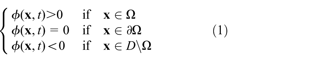
where D is the reference domain to contain all permissible shapes of the design domain
The optimization is achieved by solving the following Hamilton–Jacobi equation

where t is the time and velocity
Optimal synthesis of compliant mechanisms and the challenge of de facto hinges
Conventional mathematical formulation of the optimization problem
Synthesis of compliant mechanisms has been formulated in many different ways under two main groups. The first of which is to establish the objective function by maximizing a mechanical measurement, such as the mechanical advantage (MA), 2 the GA,6,37 and the mechanical efficiency (ME). 32 The second of which is formulated by considering both flexibility and compliance to meet the function and strength requirements. 11 A comparison study of these formulations can be found in Deepak et al. 35
For designing compliant mechanisms with single input–output behavior, the design domain can be illustrated in Figure 1 where

The design domain of topology optimization of compliant mechanisms.
In this study, in selecting the stiffness of
Here, we choose GA to quantify the performance of the compliant mechanisms. Incorporating with the level set method, a conventional formulation for topology optimization of the compliant mechanisms can be formulated as follows 37

where


where
Using the dummy load method,
2
the displacements

where
and

De facto hinge problem
A hinged compliant inverter which is obtained using equation (3) is shown in Figure 2. These kinds of hinges are not needed since they make the obtained compliant mechanisms very difficult to fabricate, especially in the micro-scale. 4 Since the flexibility of the mechanism is only provided in localized areas (hinge areas), the stress in the hinge areas would approach very high and the mechanism would break.
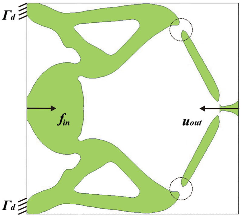
A compliant displacement inverter mechanism suffers from the de facto hinges, which are marked with dashed line circle.
The reason for de facto hinges lies behind the objective formulations. 36 In fact, for designing compliant mechanism, many developed formulations specify two main purposes, that is, maximizing the elastic deformation at the output port, meanwhile minimizing the overall compliance. This makes the true optimum of the problem a rigid-body linkage with revolute joints. The reason is that it can generate the largest output motion and has the minimum strain energy. From this point of view, the de facto hinges are inevitable. There are some other formulations that try to avoid these two main purposes to avoid the de facto hinges, such as the characteristic stiffness formulation. 37 A comparative review of those formulations can be found in Deepak et al. 35
The output stiffness and a new formulation
For topological synthesis of a compliant mechanism, although the optimum mechanism could not be known in advance, all the three regions (input region, output region, and fixed region) must be connected to one another in order to form a meaningful structure. 5 Here, we proposed an output compliance that can be built in the conventional formulation (equation (3)). The idea of designing the hinge-free compliant mechanisms by augmenting the conventional optimization problem with additional energy functionals is not new. For example, Luo et al. 32 proposed an augmented objective function using a quadratic energy functional to control the geometric width of the mechanism. However, it is difficult to implement this formulation to other topology optimization methods, such as the SIMP method or evolutionary structural optimization method. 38
As shown in Figure 3, the output stiffness

and this makes the proposed formulation very easy to use since no extra finite element analysis needs to be addressed.
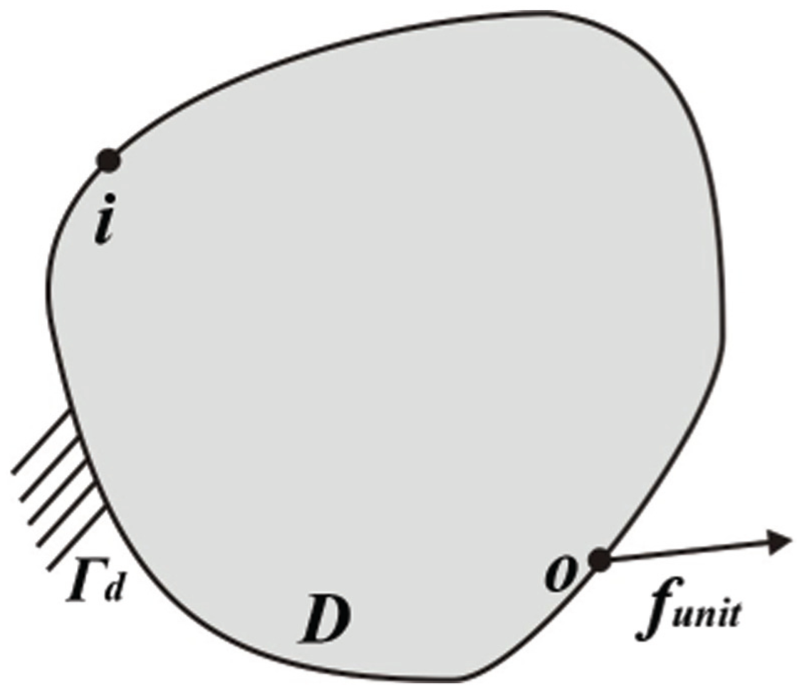
Schematic for determining
The reason for introducing the energy function to prevent de facto hinges can be stated as follows. As shown in Figure 4(a), for a compliant mechanism that suffers de facto hinges, when the mechanism is loaded with a force at the output port, the corresponding displacement at the output port will approach very high since the surrounding materials of the de facto hinges undergo essentially rigid-body rotations. This is also fairly intuitive as shown in Figure 2. However, when the mechanism is completely free of de facto hinges as is shown in Figure 4(b), when the mechanism is loaded with a force at the output port, the corresponding displacement at the output port will become smaller, that is

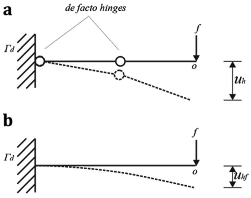
Schematic of a (a) hinged and (b) hinge-free compliant mechanism.
This means a hinged compliant mechanism corresponds to a large displacement while a hinge-free compliant mechanism corresponds to a small one. Conversely, by minimizing the displacement at the output port due to the unit load (which is equivalent to minimize the output stiffness
Based on the above analysis, the objective function can be set by minimizing

where
Shape sensitivity analysis
In order to obtain the sensitivity of the objective function with respect to the boundary perturbations, the shape derivative method39,40 is employed. The optimization problem represented in equation (11) is reformulated using Lagrange’s method of undetermined multipliers as follows
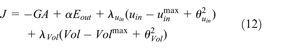
where
Applying the Kuhn–Tucker conditions of J leads to


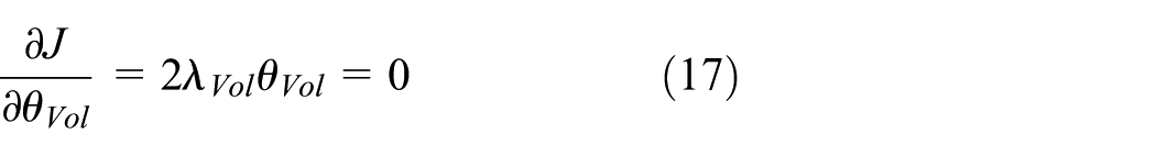

where
Equation (13) can be expressed as

where


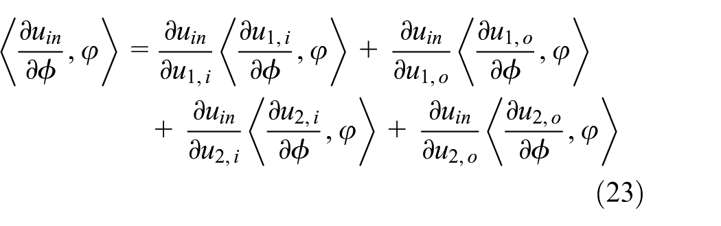
In order to calculate the shape sensitivity of J, we need to calculate the shape sensitivities of the individual functions, that is,
Taking Fréchet derivative of the GA with respect to

Furthermore, taking Fréchet derivative of the
Since
The Fréchet derivative of

where
Similarly, the Fréchet derivatives of

The derivative of allowable material usage Vol with respect to

Numerical implementation
For the implementation of the proposed method, a number of numerical issues need to be addressed here. The second-order accurate essentially non-oscillatory (ENO2) 18 is employed for solving equation (2).
In order to ensure stability, the following re-initialization equation 42 is used

where

where
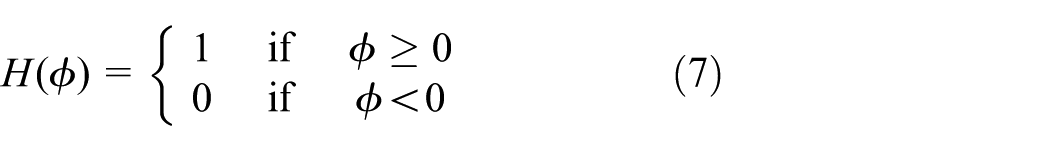
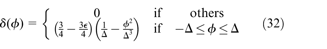
In order to avoid the numerical difficulties, we adopted the method proposed in Wang et al. 15 in which the Heaviside function is approximated using equation

where
Numerical examples
In this section, in order to demonstrate the validity of the proposed formulation, we present several examples. The used artificial material properties are as follows: Young’s modulus for solid material is
Displacement inverter
The designing of the displacement inverter is first considered. The design domain is shown in Figure 5. The length and height of the design domain have the same size. The left top corner and the left bottom corner are fixed. A single horizontal load

The design domain of the displacement inverter topology optimization problem.
Effect of
on the optimum topology
This section is focused on examining the effectiveness of
Five cases are studied, in which

Topology optimization of the displacement inverter using equation (11) with different
The value of
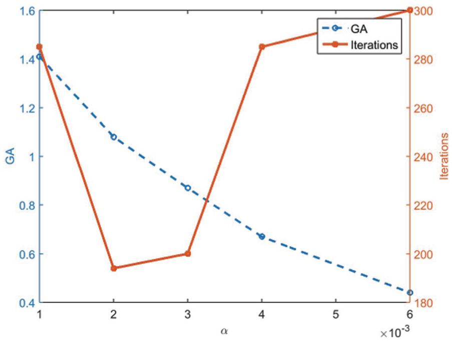
The effect of
In fact, equation (11) can prevent de facto hinges not only in the final topology but also during the optimization process. This can be seen from some intermediate designs of the displacement inverter with
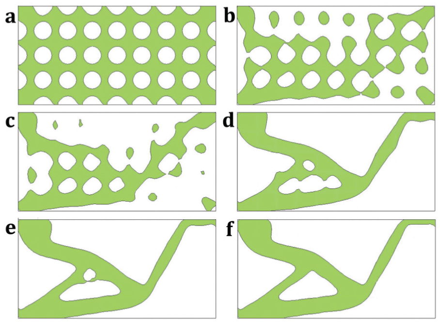
The intermediate designs of the displacement problem with

The convergence histories of the displacement inverter problem with
Push gripper
The design of the push gripper has been widely studied previously, and the design domain and boundary conditions are shown in Figure 10. The goal of the design is to achieve a mechanism that when a horizontal force is applied at the input port of the mechanism, the opposing output ports move vertically and therefore it is capable of gripping a workpiece. The design domain is discretized by
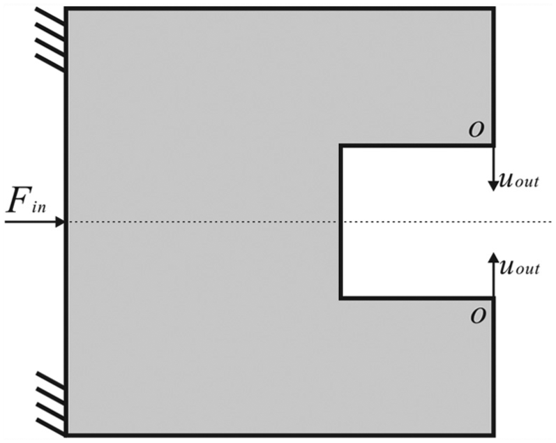
The design domain of the push gripper topology optimization problem.
The final designs obtained using the proposed formulation are shown in Figure 11. The corresponding level set surface plots are shown in Figure 12. Note that only half of the design domain is plotted in Figure 12 due to the symmetry. One can confirm that there are no de facto hinges occurring in the created mechanisms and this can confirm the capability of the proposed formulation (equation (11)) for designing hinge-free compliant mechanisms.

The final designs of the push gripper mechanism.
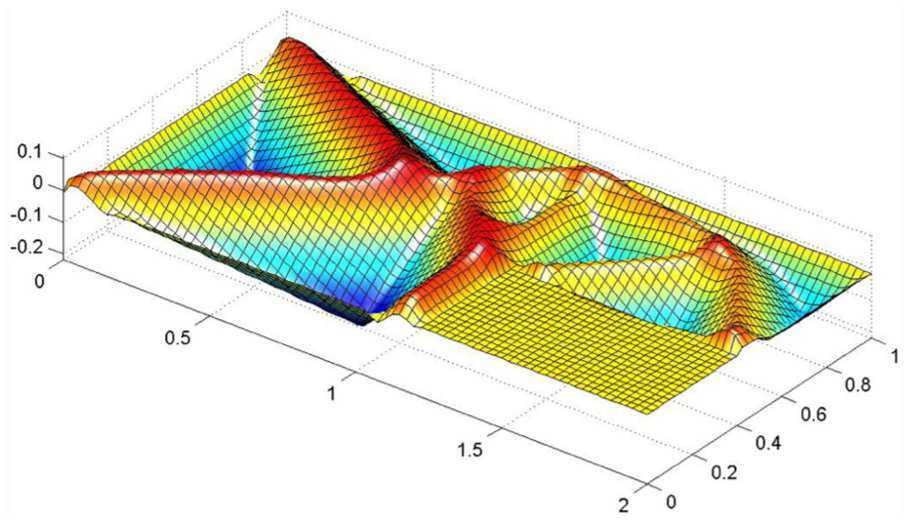
Level set surfaces of the optimal topologies of the push gripper mechanism (only half of the design domain is plotted).
Conclusion
A simple yet efficient formulation for topology optimization of hinge-free compliant mechanisms is presented by taking into consideration an output stiffness. The level set method is used for modeling the optimization problem. The proposed method is examined by topology optimization of two benchmark compliant mechanisms, that is, the displacement inverter and the push gripper. It is shown that the augmented objective formulation can prevent de facto hinges. Although only the level set method is considered, the implementation of the proposed formulation to other topology optimization methods should be straightforward. The present method can be used as an alternative method to partially control the de facto hinges of the linear elastic mechanisms. Our future research will investigate the validity of the presented method for designing both 2D and three-dimensional (3D) large-displacement compliant mechanisms.
Footnotes
Academic Editor: Fakher Chaari
Declaration of conflicting interests
The author(s) declared no potential conflicts of interest with respect to the research, authorship, and/or publication of this article.
Funding
The author(s) disclosed receipt of the following financial support for the research, authorship, and/or publication of this article: This work was supported by the Open Fund of Key Laboratory of Robotics and Intelligent Manufacturing Equipment Technology of Zhejiang Province (RIE2016OSF02), the China Postdoctoral Science Foundation Funded Project (Grant No. 2016M590772), and the National Natural Science Foundation of China (Grant numbers 51275174, 51605166). This support is greatly acknowledged.