
Abstract
To reduce radial noises from the motor of centrifugal pumps, this study designed a water cooling system called jetting equipment to replace traditional fan cooling systems in pump motors. By measuring radiated noises, head, efficiency, and cavitation performance, the research compared the differences among experimental results of the original pump unit, the one with a normal design jetting pipe and another one with a larger jetting pipe. Results show that the radiated sound pressure level of the model pump was significantly reduced by 8.3 dB after integrating the jetting pipe. With a normal jetting pipe, no significant changes were observed in the head, efficiency, and shaft power curves, and cavitation performance improved under small flow rate. However, the performance with the larger jetting pipe worsened, except the hump phenomenon of the model pump under a small flow rate was enhanced. Computational fluid dynamics method was used to calculate the internal flow of three model pumps in order to investigate the jetting flow effect. A comparison among the flow fields at the inlet of the three types of pumps indicated that high-pressure water injection can effectively control inlet recirculation and improve velocity distribution in the inlet flow field with decreased recirculation vortex strength and recirculation onset critical flow rate.
Keywords
Introduction
As one of the most important fluid transportation and energy conversion devices, the centrifugal pump has been widely used in various applications and fields, including ships, submarines, and aeronautics.1,2 With the trend of increasing speed and efficiency as well as higher environmental standards and greater client requirements, radiated noise control of centrifugal pumps has become an important problem that requires a prompt solution. Traditional motor centrifugal pumps consist of a motor and a pump. The noise mainly includes hydraulic noise caused by inner flow, mechanical noise, and motor noise. 3 Heat dissipation of the pump system always operates with the assistance of a fan, which is usually set at the end of the motor with high rotating speed. Hence, a fan cooling system is the main reason for radiated noise of motor centrifugal pump systems.
This problem was previously addressed by designing a water cooling system to reduce radiated noises. However, this approach increases designing and operating costs. The pump itself is used for liquid transportation, which is why some researchers attempted to employ jetting equipment. In this approach, the liquid goes from the outlet of the pump and back to the inlet after cooling the system of the motor. With partial high-energy flow guided back to the inlet, the inner flow of the pump is likely to be influenced, especially at the inlet. Centrifugal pumps under a small flow rate may exhibit reverse flow and cavitation. Studies have shown that this condition may cause hydraulic vibration and noises as well as result in pipe blockage.4–7 Cui et al. 8 state that reasonable jetting equipment may improve cavitation performance of high-speed centrifugal pumps based on experimental and theoretical analysis. Yang et al. 9 and Zhang et al. 10 focus on the influence of high-pressure fluid to control the backflow phenomenon. However, the above-mentioned research focuses only on the effect of high-pressure fluid on the inlet alone. Few comprehensive studies focus on synthesized jetting equipment.
This article changed the fan cooling system of a traditional centrifugal pump into water cooling one with jetting equipment. By measuring radiated noises, head, efficiency, and cavitation performance, the research compared the differences among experimental results of the original pump, the one with a normal jetting pipe and another one with a larger jetting pipe. Subsequently, the entire flow field of the pump model, including the pump chamber and jetting flow, was established to process the numerical simulation. Internal flow fields of the three pump models were calculated based on Reynolds-averaged Navier–Stokes model to analyze the backflow phenomenon and the controlling effect on this phenomenon.
Design of jetting equipment and test introduction
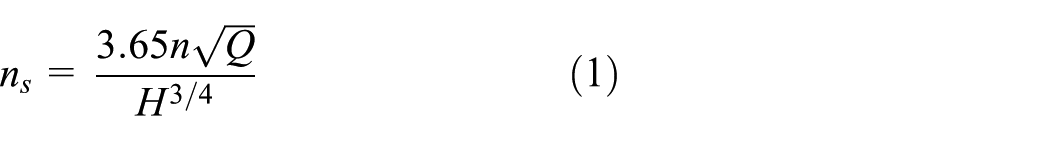
The selected model is a commercial single-stage, single-suction, horizontally oriented centrifugal pump, which has specific speed of 88.6. The specific speed of the pump is defined as shown in formula 1. The pump casing is typically combined with a spiral volute. The design parameters of the pump are shown in Table 1. In this type of pumps, the motor shaft directly drives the impeller, which allows to design a jetting equipment instead of the fan cooling system. The model pump and the design of the jetting equipment are shown in Figure 1
Pump parameters.


Schematic diagram of model pump and the design of jetting device: (1) impeller, (2) pump casing, (3) sieve, (4) screw, (5) steady pressure jar, (6) valve, (7) cavity, (8) motor casing, (9) cavity, (10) pipe, and (11) jetting pipe.
Motor characteristics and electromagnetic calculation indicate that the total cost of the motor, named PL, is equal to 1.5 kW. During stable operation of the motor, the costs will be transformed into thermal energy, which is then utilized by recycling water. Hence, the required radiating power is also 1.5 kW. According to the formula on thermal energy absorbed from the water jacket by the cooling water

where α is the convective heat transfer coefficient, which is equal to 1200 W/m2 K; ΔT refers to the difference in temperature between water-jacket wall and water, which is equal to 15°C; 11 and l is the length of helical water groove, where the water jacket determined by the motor’s construction is around 2.5 m long. As a result of bidirectional convection, the equivalent length is 5 m. The thermal energy Φ′ absorbed by water should be larger than the radiated heat from the motor. Hence, after calculation, the diameter of the water-jacket pipe should be larger than 5.3 mm. Therefore, 6 mm is selected in this study for processing convenience. Detailed structural design of this water-cooled electric centrifugal pump could be seen in patent documents. 12 Since the diameter of jetting pipe plays a major role, a larger diameter, namely, 12 mm, is also designed to process the investigation on the influence of jetting equipment on the characteristics of centrifugal pump.
Experiments were conducted in a closed-loop system, the installation diagram of which is shown in Figure 2. The inlet gate valve was kept open during the measurement, and the outlet gate valve was used to regulate the flow. A turbine flow meter was used to measure flow Q. Turbine flow meter precision is ±0.3%, and output standard electrical signal ranges from 4 to 20 mA. Speed n is measured using a tachometer. During the experiment, two dynamic pressure transmitters which have a ±0.2% precision and are capable of producing standard electrical signals were used to measure the inlet pressure (Ps) and the outlet pressure (Pd). Measurement range at the inlet is −100 to 100 kPa and that at the outlet is 0 to 1 MPa. A vacuum was used to process the cavitation performance measurement. Based on each measurement device, comprehensive error of this test rig on testing pump performance could satisfy the second level of national standards of China GB/T3216-2005 and also International Organization for Standardization (ISO) 9906:1999.

Test rig of the centrifugal pump measurement: (1) cavitation tank, (2) inlet butterfly valve, (3) model pump, (4) piezometer tubes, (5) voltage regulator tank, (6) turbine flow meter, (7) outlet butterfly valve, and (8) vacuum pump.
In the test rig shown in Figure 2, the following experiments were processed on the original pump, 6 mm jetting pipe, and 12 mm jetting pipe equipment: (1) experiment on radiated noises, (2) model pump performance at fixed rotary velocity, and (3) cavitation experiments at different flow rates and fixed rotary velocity. The sound pressure level of pump-radiated noises was collected using a digital sound level meter, whose resolution is ±0.1 dB. During the experiment, the inlet valve was fully open, and the outlet was closed before turning on the centrifugal pump. We adjusted the frequency converter to keep n, the pump rotary velocity, fixed at 2900 r/min, while exporting air in the voltage regulator tank. Through control of the outlet valve, 25 flow rate points from 0 to 1.4 Qn were used to define pump performance. Signals of static pressure at the inlet and the outlet, rotary velocity, flow rate, and motor parameters were collected during stable operation. With regard to cavitation measurement, the experiment was processed under three flow rates, namely, 0.7 Qn, Qn, and 1.2 Qn, with fixed rotary velocity and adopted reducing available net positive suction head (NPSHa) method to obtain cavitation performance curves. After each vacuum pumping, we collected the outlet static pressure, rotary velocity, and electric parameters when the system was stable. At each mass flow rate, 20 groups of data are collected.
Test results
Measurement results of radiated noise from three pumps
The radiated noise experiments of three pump models were carried out based on ISO 4412-1:1991. 13 The testing point is located horizontally 1 m to the surface of the pump body as shown in Figure 3(a). Sound pressure level of the pump was calculated by the average of all measuring points. Figure 3(b) shows the sound pressure level variation in accordance with the flow rate for the three pump models. The sound pressure level of the three pumps that the original pump, the pump with a 6 mm jetting pipe and the pump with a 12 mm jetting pipe initially increased with the flow rate and then decreased with the flow rate to the lowest point at the designed flow rate and increased soon. This conclusion is in accordance with the flow-induced noise measurement of the inner pump flow field. 7 Greater mass flow rate may cause cavitation, which would cause head reduction and increased radiated noises. Moreover, the average sound pressure of the system noise was reduced by approximately 8 dB before the motor fan was removed, and the difference between 6- and 12-mm-diameter jetting pipe was not evident, with an average of 0.3 dB because of large background noise. Figure 3(c) displays the sound pressure level variation along with the decrease in inlet pressure. The noise levels of the original pump and those of the pump with a 6-mm-diameter jetting pipe increased suddenly when the pressure was less than −60 kPa. A similar law applies to the pump with a 12-mm-diameter jetting pipe when the inlet pressure was less than −50 kPa, which may indicate that cavitation occurred. The average sound pressure of system noise following the decrease in inlet pressure reduced to 79.2 and 79.9 dB from 86.87 dB before the motor fan was removed. Overall, the radiated noises of the pump system with 6 mm diameter jetting pipe showed the best results.

Sound pressure level of radiated noises from three pumps: (a) SPL measurement points, 13 (b) SPL variation with increased mass flow rate, and (c) SPL variation with decreased inlet pressure at Q = Qn.
Measurement results of performance curves from three pumps
Figure 4 shows the head, efficiency, and shaft power curves in accordance with flow rate. Compared with the original pump, the pump with a 6 mm jetting pipe has little differences in head, efficiency, and shaft power. By contrast, the pump with a 12 mm jetting pipe has apparent differences in head, efficiency, and shaft power. Under a small mass flow rate, the pump with a 12 mm jetting pipe more obviously favored the hump of the head curve. This pump consumes more energy than the other two because the jetting pipe enlarged the impeller flow. With the mass flow rate of the pump increases, efficiency and head dropped quickly because the jetting pipe flow enlarged the real flow rate at the impeller resulted in cubage loss.

Comparison of pump performance: (a) head, (b) efficiency, and (c) shaft power.
Measurement results of cavitation performance curves from three pumps
High-energy fluid guided by jetting equipment from the outlet to the inlet of the pump results in a transformation into pressure energy at the inlet. Hence, the fluid may enhance cavitation performance theoretically. Figure 5 shows the cavitation curves of the three model pumps under 0.7 Qn, Qn, and 1.2 Qn. NPSHr, which is the critical cavitation margin, is set based on the margin when the head drops by 3%. Results show that NPSHr always increases along with mass flow rate for all three model pumps, which shows the same conclusion in other literatures. 14 Under 1.2 Qn, relatively strong unstable cavitation was observed on the curve as a hump appeared in the original pump, whereas the jetting flow could improve this condition. Compared with the original pump, NPSHr decreased slightly under 0.7 Qn for the pump equipped with 6-mm-diameter jetting pipe, but increased under Qn and 1.2 Qn. It makes sense that the recirculation of high-stagnation pressure fluid caused by the jetting pipe flow could enhance cavitation performance because it brings higher saturation pressure margin under 0.7 Qn. In the pump equipped with 12-mm-diameter jetting pipe, NPSHr increased under all three mass flow rates. This condition occurs because higher leakage caused by the jetting pipe worsens cavitation performance and vertical jetting flow into the inlet pipe, thereby disturbing the flow pattern, both of which balance out the improvement.

Cavitation performance curves: (a) Q = 0.7 Qn, (b) Q = Qn, and (c) Q = 1.2Qn.
Numerical simulation of the influence of jetting equipment on pump inlet flow field
The measurements showed that the jetting equipment significantly influences the inlet flow field of the pump, which results in variation in the performance and cavitation curves. 15 Backflow phenomena is always observed at the inlet when the pump operates at small mass flow rates, which may disturb the surrounding flow field and cause vibration and noise problems. 16 Import pressure at the inlet is an effective way to control the backflow. Therefore, this section carried out numerical solutions on the entire flow field of the three pump models as well as analyzed the effect of jetting flow on pump inlet flow field using computational fluid dynamics (CFD) method.
Three-dimensional calculation model and simulation method
The clearance flow between the pump chamber and the impeller inlet has a great effect on the inlet flow field of the pump, which has been considered to be the main reason for the calculation deviation. 17 Therefore, we built the hydraulic model in strict accordance with the size of centrifugal pump flow components. To minimize the interface number, the model is divided into five parts: inlet pipe, outlet pipe, jetting pipe, impeller (rotating domain), and pump casing (stationary domain), which includes the volute and the side chambers between the impeller and the volute to take leakage flow effects into account, as shown in Figure 6. Inlet and outlet pipe domains were carried out to extend the treatment to ensure that the flow, including the jetting flow, closed in a fully developed condition at the inlet and outlet, thereby providing better results for the flow structure.

Three-dimensional model of calculation domain: (1) inlet pipe, (2) impeller, (3) pump casing, (4) outlet pipe, and (5) jetting pipe.
Structured grids of the domains were generated with ICEM-CFD 12.1, and care was taken to concentrate on the grid in the wear rings and tongue region of the volute, as shown in Figure 7(a). The total number of grid nodes is 5,445,910, and the number of grid elements is 5,207,832 for rotating and stationary domains of the original pump. Similar independence of the solutions from the number of grid nodes has been proven by simulating the flow field with different numbers of grid nodes according to previous work.18,19 The only difference in the pumps with jetting equipment is the addition of the jetting pipe domain in the calculation, with a total number of grid nodes of 5,495,910 and with diameters of 6 mm and 5,565,910 with diameters of 12 mm. The near-wall mesh was applied to ensure non-dimensional normal distance from the blade surface, that is, y+, located in the suitable region because of the adopted automatic near-wall treatment. As shown in Figure 7(b), the distributions of y+ are below 20, as obtained in the pump casing and also the blade surface.

Grid view in computational region and distribution of y+: (a) mesh and (b) y+ distribution in the pump casing.
Based on the finite volume method, the three-dimensional (3D) steady turbulent flow in pumps was simulated under different conditions using the shear stress transport (SST) turbulence model. The total pressure was specified at the inlet of the suction pipe, whereas the outlet condition is mass flow rate, both of which were obtained from laboratory tests. The internal and external impeller surfaces were modeled using a rotating wall, in which the speed equals the nominal rotating speed, whereas all other walls were stationary. A smooth wall condition is used for the near-wall function. Furthermore, the interfaces between the rotor and their neighboring sub-domains were set up as frozen rotors, which is a common procedure for steady-state calculation. In addition, iteration stops when the root mean square residual dropped below 10−5.
Discussion of numerical simulation results
Analysis of the inlet flow field from original pump calculation
Figures 8 and 9 show numerical simulation results of the original pump with overall flow field calculation. In comparison with experiment results, the numerical ones always appear to be higher than the experiments as shown in Figure 8(a). This difference is within 5%, which means numerical results could be used for further research. The research sets several monitoring points (shown in Figure 8(b)) along the radius on the circular impeller’s center. L represents the distance from a monitoring point to the center. Axially directed velocities at the inlet section are presented in Figure 8(c). The direction that points to the impeller is defined as positive. Backflow may appear when the pump is working with a small flow, which leads to alternative distribution of axial velocity at the impeller inlet section. Negative axial velocity appears on the section when the flow is reduced to about 0.7 Qn. The backflow area enlarges with continuous reduction of flow rate and increased backflow velocity, whereas the main flow area and velocity continue to decrease. When flow rate further decreases to 0.3 Qn, the backflow area follows to block the partial conduit. The velocity and radial thickness of backflow are also higher. Eddy viscosity of recirculation vortex distribution under different conditions of the original pump is shown in Figure 9. It exhibits different sizes and locations of backflow vortex that are present with mass flow rate decrease. Backflow vortex initially occurs near the front shroud. When working condition was set to 0.8 Qn, backflow vortex occurred in the impeller conduit only and did not lead to prewhirl beyond the inlet edge. The vortex eddy core was stretched to the inlet edge of the impeller when it is reduced to 0.7 Qn. The vortex eddy continued to strengthen with the decrease in flow rate. Meanwhile, the vortex center moved upward into the inlet pipe and blocked the conduit until most of the passage was obstructed with increasing eddy volume under the condition of 0.3 Qn. In summary, the critical flow we found at the inlet is 0.7 Qn for this pump, and the backflow phenomenon is relatively obvious and remains stable when it is 0.6 Qn.
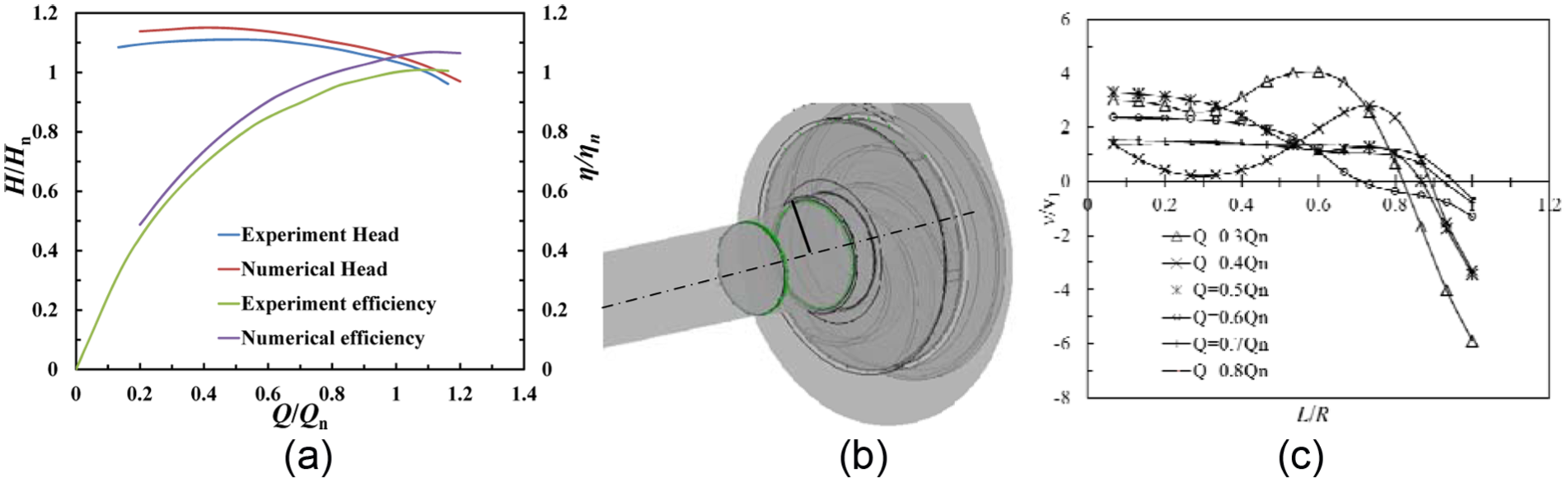
Variation in axial velocity component in the central line of inlet cross section: (a) validation of CFD results, (b) central line of inlet cross section, and (c) axial velocity distribution.

Eddy viscosity of recirculation vortex under different conditions of original pump: (a) Q = Qn, (b) Q = 0.7 Qn, (c) Q = 0.6 Qn, and (d) Q = 0.3 Qn.
Analysis of inlet flow field after adding jetting equipment
The backflow phenomenon is relatively obvious and remains stable. Therefore, the backflow controlling effect is analyzed primarily under 0.6 Qn. Figure 10 shows the velocity distribution at the inlet flow field of the three pump models under 0.6 Qn. Negative velocity fluid close to the front cover of the impeller extends to the inlet pipe at high speed for the original pump as shown in Figure 10(a). Moreover, the negative velocity fluid is strong enough to form the backflow vortex at the impeller import. The velocity distribution at the inlet of pumps with jetting equipment, as shown in Figure 10(b) and (c), clearly shows that adding jetting pipe could achieve a better effect to control backflow from the impeller. The effect is more obvious with a larger jetting pipe diameter. However, inappropriate jetting fluid vertically injected into the inlet tube negatively influences inlet flow field. It forces fluid concentration into the center of the inlet pipe with irregularity. A larger jetting pipe diameter corresponds to more obvious changes in the flow field.

Velocity distribution at the inlet flow field of the pump: (a) original pump, (b) dy = 6 mm, and (c) dy = 12 mm.
Moreover, eddy viscosity of recirculation vortex in the impeller, under different conditions of pumps with jetting pipes, is shown in Figures 11 and 12. According to Figure 11, in the condition with 6 mm jetting pipe, volume and intensity of backflow area are reduced, and the apparent backflow phenomenon relatively decreased to 0.6 Qn. These results indicate that the jetting pipe could obtain a better effect to control the backflow from the impeller. However, the jetting flow would increase localized vortex intensity within the impeller channel. In addition, an asymmetric vortex core appeared because of the jetting flow, which would also be affected negatively. A better opinion is to set the jetting pipe symmetrically along the centerline of the inlet pipe and at an appropriate incidence angle. Under the condition with a 12 mm jetting pipe, the jetting flow always has an obvious negative influence. Global vortex intensity increased under all pump operating conditions, and a large vortex core constantly existed in the inlet pipe.

Eddy viscosity of recirculation vortex under different conditions of pumps with dy = 6 mm: (a) Q = Qn, (b) Q = 0.7 Qn, (c) Q = 0.6 Qn, (d) Q = 0.4 Qn, and (e) Q = 0.3 Qn.

Eddy viscosity of recirculation vortex under different conditions of pumps with dy = 12 mm: (a) Q = Qn, (b) Q = 0.7 Qn, (c) Q = 0.6 Qn, (d) Q = 0.4 Qn, and (e) Q = 0.3 Qn.
Evaluation of the ejector flow rate
Finally, a necessary step is to evaluate whether the ejector flow rate meets the needs of the motor cooling and its influence on the inner flow. Figure 13 shows the ratio of the ejector flow account for the flow rate in the impeller under various non-dimensional mass flow rates from numerical results. Figure 13 indicates that the percentage is too high for the pump with a 12 mm jetting pipe, which mainly caused the negative effect on the pump characteristics. For the ratio with a 6 mm jetting pipe, it is maintained within a reasonable range under large mass flow rates, while remain high under small mass flow rates. Moreover, pumps under small mass flow rates need less cooling water for motor radiation. Therefore, installing a valve in the jetting pipe to control ejector flow rate might be a convenient scheme.
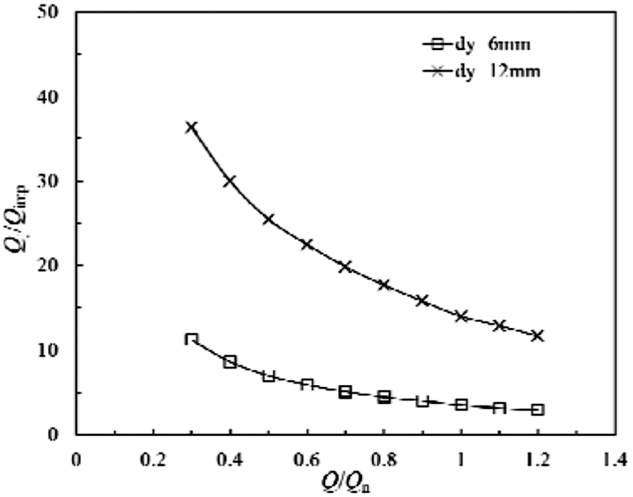
Flow percentage of the ejector flow.
The necessary ejector flow for motor cooling could be calculated using the following formula

where
Conclusion
Experiments were performed on motor centrifugal pumps with jetting pipes with two diameters. Measurements were divided into sound pressure level, head, efficiency, shaft power, and cavitation performance tests. Afterward, numerical simulation was performed on the three types of pumps to analyze the influence on the inlet field. The following conclusions could be drawn:
The jetting device greatly reduced the radiated noise of the original pump by an average of about 8.3 dB, and the sound pressure level of pump with a 12 mm jetting pipe is slightly larger than that of the normal jetting pipe, with about 0.3 dB on average. This result shows that fan noise plays an important part in radiated noise of the pump system, while fluid motion in the pump presents imperceptible effects.
For the pump with a 6 mm jetting pipe, which is the normal design of the jetting equipment, little differences in head, efficiency, and shaft power curves were observed. The pipe also positively influences pump cavitation performance characteristics, such as decreasing NPSHr under small mass flow rate and eliminating the hump on cavitation performance curves under a large mass flow rate. However, for the pump with a 12 mm jetting pipe, great leakage fluid from the jetting pipe resulted in comparatively large losses and increased the impeller flow rate, both of which lead to rapid decline in head and efficiency curves. Moreover, cavitation performance of the pump with a 12 mm jetting pipe did not improve because of disturbance to the inlet pipe flow.
Numerical simulation based on the entire flow field of the original pump shows that backflow starts to appear at 0.7 Qn, and the backflow area increased when the flow rate decreased. Adding normal design jetting equipment resulted in a better control of the impeller on the backflow; the eddy intensity decreased under all operating conditions, and the critical point of obvious backflow phenomenon was delayed to 0.6 Qn. However, negative effects were always observed on the inner flow field of the inlet pipe and impeller because of significant leakage. Moreover, a better approach is to decrease the ejector flow under small pump flow rates.
Footnotes
Appendix 1
Academic Editor: Yuning Zhang
Declaration of conflicting interests
The author(s) declared no potential conflicts of interest with respect to the research, authorship, and/or publication of this article.
Funding
The author(s) disclosed receipt of the following financial support for the research, authorship, and/or publication of this article: The researchers gratefully acknowledge the financial support by National Natural Science Foundation of China (Grant No. 51509108), the Natural Science Foundation of Jiangsu Province (Grant No. BK20150516), the China Postdoctoral Science Foundation (Grant No. 2015M581735, Grant No. 2016T90422) and Senior Talent Foundation of Jiangsu University (15JDG048).