
Abstract
In this study, a novel magnetorheological brake with multi-pole and dual-gap configuration is presented to increase not merely the torque output but also the range of controllable transmission torque while maintaining a compact structure. In addition, the proposed magnetorheological brake design features several individual coils, and lower power consumption for a desired torque output could be obtained by properly controlling the input currents in those coils. Theoretical research has been done in order to reveal the relationship between the novel structure and the output torque and obtain the mathematical formulas of the output torque. Then, based on the theoretical research, finite element analysis was performed to optimize the structure, analyze the magnetic field distribution, and evaluate the capability of the designed magnetorheological brake. Finally, an optimization was performed to obtain the minimum power consumption for a desired torque. The results show that the proposed magnetorheological brake can generate a considerable torque density in its dimensions while maintaining controllable power consumption by individual input currents.
Introduction
Magnetorheological (MR) fluid is an intelligent material consisted of a suspension of micrometer-sized ferromagnetic particles dispersed in a carrier fluid (typically water, mineral oil, synthetic oil, or glycol). In the absence of an applied magnetic field, an MR fluid can be considered as a Newtonian fluid. However, when a magnetic field is applied, it solidifies and develops a yield stress due to the fact that the particles are gathered to form chain-like structures in the direction of the magnetic flux paths. That is to say, this fluid experiences a liquid-to-solid transition on the application of the field. Over the past decades, there has been an increasing interest in its engineering applications, such as MR dampers,1–5 MR valves,6,7 shock absorbers, 8 MR clutches9–11 or brakes,12–15 and engine mounts.16,17
In recent years, MR fluid has received considerable attention for applications in a variety of torque transmission devices, such as brakes, clutches, and soft starters for mechanical equipment. In general, MR transmission devices commonly take the form of a disk type or a cylindrical type. For a disk type, the MR fluid is placed in a small gap which is perpendicular to the rotation axis, while under the circumstances of a cylindrical type, the MR fluid is working in an annular gap which is parallel to the rotation direction. The magnetic field strength within the MR fluid is supplied by the coil current. Thus, the torque generated by the brake can be controlled by setting the magnitude of the input current.
Unlike MR dampers which have been used in commercial vehicles, the current development of the MR brakes cannot meet the requirement of engineering application. The major issue is that the transmission torque of the MR brakes is still too small in a constrained volume and weight. As far, several searches have been done for the purpose of increasing the output torque, such as increasing the working area of the MR fluid,18–20 reducing the thickness of the fluid gap,15,21 increasing the magnetic field strength within the MR fluid, or using the MR fluid with a higher yield shear stress. 22 As we know, the magnetic field strength within the MR fluid is limited to magnetic saturation, and the maximum yield shear stress of commercial MR fluids is not more than 100 kPa. In addition, it is more difficult to reduce the fluid gap in an MR brake because of the limitations in manufacturing. Thus, the most effective method of the torque enhancement is to increase the working area of the fluid.
To increase the working area, the common solution so far is using several working disks in parallel along the rotation direction. Kavlicoglu et al. 23 developed a multi-plate MR limited slip differential clutch, which is composed of 43 pairs of driving disk and driven disk. Zhou et al. 24 studied a compact double-disk MR fluid brake with two shear disks and a coil. Karakoc et al. 13 designed a multi-disk with two disks and optimized for higher braking torque and lower weight. Wang and Hou 25 designed a multi-disk MR fluid actuator with three drive disks and four driven disks, and the acquired maximum torque is 285 N m with a height of 384 mm and a width of 265 mm. Dai et al. 18 designed and analyzed of a novel composite MR fluid clutch, which is combined of disk type and cylindrical type. Wang et al. 26 also proposed a novel two-layer multi-plate MR clutch for high-power applications, and the torque is up to 1545 N m while applying 2 A current to the coils. In summary, the method of increasing the working area of MR brakes can increase the transmission torques to some extent, but it would inevitably lead to a large axial size. For disk type, the torque will be easily affected by the centrifugal force at high speed rotating conditions due to a long radial critical area which allows the particles to freely move outward. Besides, the magnetic field strength distribution within the MR fluid along the radial direction is not uniform, and the magnetic field strength is greater when the MR fluid in the working gap is closer to the coil. Furthermore, the relation between the number of disks and the torque in a multiple disk structure is linear, while the torque in a multiple cylinders is proportional to the square of the radius of each cylinder.
There are few researches on maximizing the torque in a given volume by increasing the number of annular working gaps. Shiao and Nguyen 27 presented a multi-pole MR brake. This brake is working in cylindrical type and is set up with several coils along the circumferential direction ensuring that the entire MR fluid in the cylinder gap can be activated. The ratio of the torque to volume of this brake is only about 13 kN m−2. Rossa et al. 19 developed a multilayered wide-ranged torque MR brake with four annular fluid gaps, and the coil is placed laterally to the cylinders. The brake has a torque to volume ratio of 48.1 kN m−2 and a maximum-to-minimum torque ratio of 176, but the magnetic field strength distribution within the MR fluid is not uniform. The magnetic field strength within the four working gaps gradually reduces from the smallest gap to the largest gap, and the closer the MR fluid is to the coil, the bigger the magnetic field strength is.
It is noted that in the aforementioned researches, the input currents in the several coils are identical. However, with several coil designs, one of the advantages needing to be noted is that the input currents can be controlled independently. This article presents the design of a high torque density multi-pole and dual-gap MR brake with individual input currents. This brake has the ability to make full use of the radial space in a given volume. To date, the advantage (e.g. lower power consumption) of such device with individual input currents has been explored. First, a novel design of multi-pole and dual-gap MR brake was presented with detailed introduction, and an optimal design of the MR brake considering the braking torque, the volume, and the geometric dimensions of the brake was carried out. Then, a finite element analysis of the optimal structure was performed to analyze the magnetic field distribution. Finally, another optimization design was performed to obtain the minimum power consumption for a desired torque, and the specifications (e.g. maximum braking torque, power consumption, and the torque-to-volume ratio) of the proposed MR brake were discussed.
Structural design and operational principle
Structure of the proposed MR brake
In this work, a new multi-pole and dual-gap MR brake shown in Figure 1 was proposed to increase the torque density in a given volume. Significant geometric dimensions of the brake are also shown in Figure 1 and Table 1. As shown in Figure 1(b), six stators (poles) made of magnetic steel create two cylindrical gaps within which rotor A and rotor B are placed. Two adjacent stators are connected by nonmagnetic materials in order to make the produced magnetic flux penetrate two MR fluid gaps. The direction of magnetic flux in each pole is opposite to that of its two adjacent poles. From Figure 1(a), one side of the six stators is fixed to the case made of nonmagnetic steel, while the other side is connected with a stator cover which is also made of nonmagnetic steel. The rotor A made of magnetic steel is fixed to the rotary shaft, and the rotor B made of magnetic steel is connected to the rotor A through a rotor ring which is made of nonmagnetic steel. The MR fluid filled between the rotating rotors (rotor A and rotor B) and the static stator and case. By such a dual-gap design, the torque output of the proposed brake is bigger than that of a single-gap configuration in the same geometry.

Proposed configuration of the multi-pole and dual-gap MR brake: (a) a 3D view of the structure and (b) the cross-sectional view showing a configuration of the stator is between the case and the stator cover.
MR brake structural parameters.
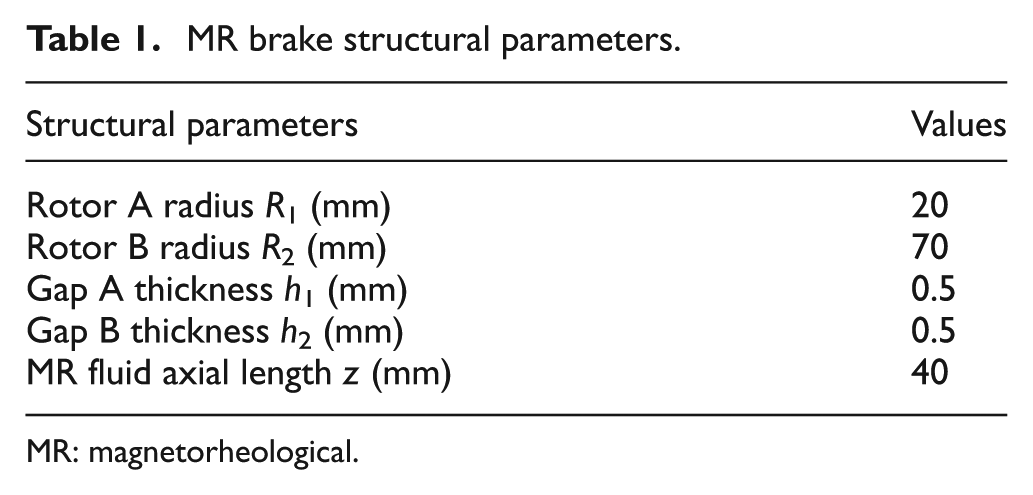
MR: magnetorheological.
As shown in Figure 2, the magnetic flux travels following the path of the black lines and arrows when all coils are energized, and it will travel in a closed loop.

Direction of magnetic flux of the multi-pole and dual-gap MR brake.
In this innovative design, the effect of centrifugal force on transmission torque is expected to be smaller than that of disk structures because of the shorter radial critical area in the former, which allows free outward movement of the particles. Also, several poles have set up along the circumferential direction, and every pole is surrounded with a multi-turn magnetic coil. It ensures that almost the entire MR fluid in two annular gaps has been activated when applying a current to the coils. In the presence of a magnetic field, MR fluid becomes magnetically permeable, and the chain of MR particles forms a route for magnetic flux to pass through. Thus, the permeable MR fluid within gap A and gap B functions as a resistance for the MR brake. Consequently, the multi-pole and dual-gap MR brake provides a more effective torque enhancement because of the design of several coils and two annular fluid gaps. The number of the poles is dependent on the size of the brake and manufacture abilities, such as 2, 4, 6, 8, 10 stators, and so on. In this article, the performance of a six poles’ MR brake has been studied.
Material selection
The MR fluid is an essential of the multi-pole and dual-gap MR brake, and its viscosity without a magnetic field and shear stress gradient with respect to the applied magnetic field strength are the standard of material selection. LORD MRF-132DG 28 was selected in this MR brake.
In the magnetic circuit design, the magnetic field lines should try to be radially directed to penetrate the MR fluid gap. And it needs to minimize the total magnetic resistance of magnetic circuit to increase the magnetic field strength within the MR fluid. According to the structural design of the multi-pole and dual-gap MR brake, the major focus on material selection was ferromagnetic materials in the magnetic circuit. Considering the cost, permeability, and availability, low-carbon steel 1018 13 was selected as the magnetic material in the magnetic circuit (i.e. rotor A, rotor B, and the poles). In addition, aluminum was used as the nonferromagnetic material to make the shaft, the magnetic separation, the stator cover, the rotor ring, and the case. American wire gauge–18 (AWG-18; Φ1.02 mm, 21.4 Ω km−1, 100 turns) copper wire was used for the multi-turn coils.
Sealing of the MR brake is another important design criterion. Since the MR fluid is highly contaminated due to the iron particles in it, the risk of sealing failure is increased. In our design, two lip-type seals employed between the static case and the rotating shaft (see Figure 1(a)) were used to seal the MR fluid in the gap. In addition, Viton O-rings were used for the static applications.
Transmission torque calculation
The key issue in this design of the MR brake is to establish the relationship between the braking torque and the input currents. The Bingham model 29 is commonly used to describe the behavior of MR fluid as a function of the magnetic flux density B. The Bingham formulation gives

where τ is the total shear stress,
Due to the fact that the gap thicknesses h1 and h2 are very small, the shear rate of the MR fluid in the gaps can be approximately determined by

where
In this study, the hydrocarbon-based MR fluid product (MRF-132DG) from LORD Corporation is used. The relationship between yield stress

In equation (3), the unit of the yield stress
The MR fluid gap A and gap B are the working areas of the MR fluid in the multi-pole and dual-gap MR brake. Regardless of the given geometry, the tangential resistive force is calculated by integrating the shear stress τ over the shearing surface. For the rotary MR brake in this article, taking into the radii

where θ is the azimuth angle in the cylindrical coordinate system and
Substituting equations (1) and (2) into equation (4), then
where
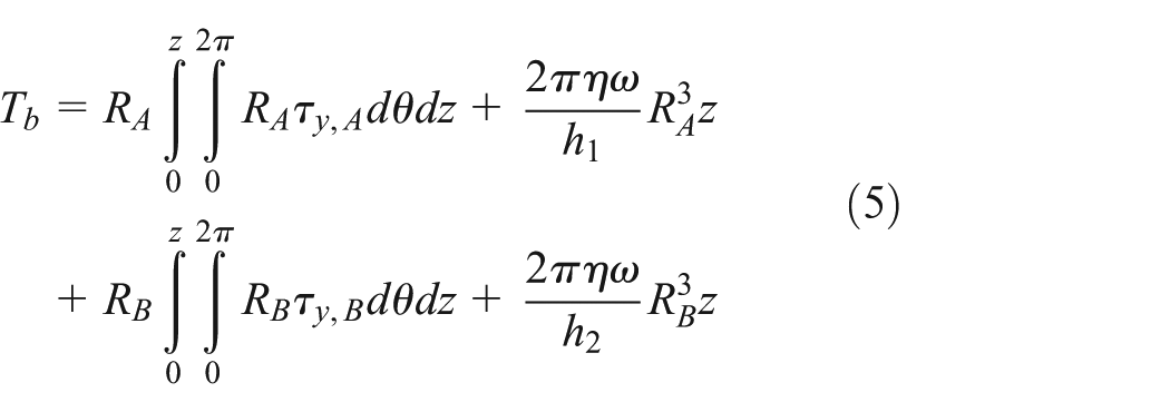
In addition, the friction torque due to the bearing parts is ignored in this work. Considering the viscous torque of nonworking areas of the MR fluid

From equation (6), the total torque generated by the multi-pole and dual-gap MR brake contains two parts: the field torque and the viscous torque. The controllable field torque which is the first term depends on the yield stress of active MR fluid and the locations of the gaps (
Optimal design of the MR brake
To improve the desired performance, the finite element analysis integrated with an optimization tool was utilized to obtain the optimal structure. For the design of a MR brake, an important issue to be taken into account is the braking torque. In addition, the whole geometric volume of the brake should also be considered for the automobile vehicles and other applications, and the space for the brake is a major constraint. As a next step, the chosen design configuration shown in Figure 1 was optimized for higher braking torque and smaller volume. In setting up such an optimization problem for the MR brake, a cost function was defined by including the braking torque and volume as functions of the structural parameters showing in Figure 1. The objective function of the MR brake optimization problem is defined as


where
The finite element method (FEM) was used to obtain
In order to solve the MR brake optimization problem, a design space was specified as the possible solution space (lower and upper boundaries of this space were defined and shown in Table 2). Then, the solution to update the solution until an optimum design was found. Figure 3 shows the optimal solution of the proposed MR brake.
Optimal solution for the multi-pole and dual-gap MR brake.

LB: lower boundary; UB: upper boundary; MR: magnetorheological.

Optimization solution of the proposed MR brake: (a) design variables and (b) objective.
The optimum dimensional parameters are given in Table 2, with the corresponding illustration already shown in Figure 1. These values have been rounded for ease of manufacture.
Finite element analysis
In this section, finite element software has been used to carry out the three-dimensional (3D) magnetostatic simulation, from which the magnetic flux density on MR fluid areas can be investigated when different magnitudes of input currents are applied to the coils. First, a 3D finite element model of the MR brake was created based on the optimal structure dimensions shown in Table 2, and the nonlinear material properties of MR fluid-132DG and low-carbon steel 1018 were defined as functions of the magnetic flux density B. Next, a magnetically isolated boundary that includes the structure geometry was selected, and six multi-coils were defined. After the mesh was generated, the model was solved using a nonlinear solver and then the magnetic field distribution onto the MR fluid (i.e. magnetic flux density B) was obtained. Finally, the braking torque in equation (6) could be calculated using a boundary integration post processing function that integrates the shear calculated by the magnetic flux density distribution, over the shear cylindrical surfaces.
Figure 4 shows the direction of the magnetic flux in the cross section of the MR brake when applying a 2 A input current to each coil. It can be observed that its travel direction is clear as a loop between two adjacent poles. The produced magnetic flux lines are orthogonally penetrating most of the MR fluid in gap A and gap B. Due to the radial magnetic flux, the MR fluid in both gaps becomes permeable and functions as a resistance source for the MR brake. The braking torque can be easily controlled by the magnitudes of the input current. This result confirms the feasibility of the operating concept of the multi-pole and dual-gap MR brake.

Flow direction of the magnetic flux in the multi-pole and dual-gap MR brake.
Two probe lines were drawn along the circumference and in the middle of gap A and gap B. Figure 5 shows the average values of radial component of magnetic flux density distribution along the middle lines of (a) MR fluid gap A and (b) MR fluid gap B, when the input currents increase from 0.5 to 3.0 A by a step of 0.5 A. The positions of the six poles are indicated by the six peaks in Figure 5(a) or (b). The magnetic flux density along the probe in gap A produces six same high peaks at a certain input current, which are 0.297, 0.516, 0.678, 0.795, 0.885, and 0.955 T when the input currents are 0.5, 1.0, 1.5, 2.0, 2.5, and 3.0 A in order. Due to structural symmetry, the magnetic flux density in gap B around six poles shows similar distributions as well as in gap A. Thus, the magnetic flux densities along the probe in gap B are 0.186, 0.330, 0.443, 0.535, 0.616, and 0.679 T when the input currents increase from 0.5 to 3.0 A with a step of 0.5 A. It is noted that the magnetic flux density in gap A is greater than that in gap B for a given current due to the fact that the magnetic flux flowing through both gaps is related to a same coil. In this case, for a given current, the smallest fluid gap will saturate before the other, and therefore, and the maximum magnetic flux is limited to the one that saturates the smallest fluid surface. Hence, given that the other fluid surface is larger, the magnetic flux density of that fluid gap is inevitably smaller. However, the torque density of the proposed dual-gap MR brake is much greater than that of a single-gap configuration, as shown in Table 3. Thus, the torque enhancement of such multi-pole design can be achieved by a dual-gap configuration.
Specifications of the proposed MR brake and comparison to others.

MR: magnetorheological.

Radial component of magnetic flux density distribution along the middle line of (a) MR fluid gap A and (b) MR fluid gap B (all six coils are energized).
The generated torque of the proposed MR brake basically depends on the axial length of MR fluid working surfaces. To investigate the magnetic field strength distribution along the axial direction in both gaps, two probe lines were drawn along the axial direction and in the middle of gap A and gap B while both are facing coil II. Figure 6 shows the radial component of magnetic flux density along the two probe lines at 2.0 A input current. From this figure, the magnetic flux density along the axial direction in both the gaps remains as a constant except that of the two ends declines a little. The small variation of the magnetic flux density at the two ends is due to the influence of the edge effects of the magnetic field in the 3D FEM simulation. This result confirms that the torque improvement of the proposed MR brake can be achieved by increasing the axial length of MR fluid surface z.

Magnetic flux density along the axial direction in both the gaps while facing coil II.
Furthermore, to investigate the magnetic flux density between two adjacent poles, another two probe lines were drawn along the axial direction and in the middle of gap A and gap B while both are between coil I and coil II. Figure 7 shows the magnetic flux density along these two probe lines when applying a 2 A input current to all the six coils. Note that the magnetic flux density in both gaps is <0.005 T, which is very low. This indicates the importance of nonmagnetic materials shown in Figure 1(b). It can be concluded that the nonmagnetic materials have almost isolated the flux from going directly from one pole via the MR fluid gap A and gap B to the other poles.

Magnetic flux density along the axial direction in both the gaps while situating between coil I and coil II.
Performance optimization
The advantage of the proposed MR brake is that each coil can be controlled independently. By properly controlling the input current in each coil, it is possible to result in a same braking torque while maintaining different power consumption. Thus, individual input current was proposed to maximize the potential for reducing power consumption. To avoid the eccentricity, for a six-coil MR brake shown in Figure 1, the configurations of coils and input currents mainly are of two categories:
Two opposite coils (i.e. coil I and IV, coil II and V, and coil III and VI) are applied currents equal in magnitude but opposite in direction while the current in each coil is opposite to that of its two adjacent coils;
Three evenly spaced coils (i.e. coil I, III, and V and coil II, IV, and VI) are applied an identical current while the current in each coil is opposite to that of its two adjacent coils.
In order to obtain the desired torque while maximizing the potential for reducing power consumption, the finite element analysis integrated with an optimization tool was used for three configurations of coils discussed above. The optimization problem is expressed as follows


where
In this study, the desired torque
Two opposite coils are a group:
Three evenly spaced coils are a group:
Six coils are applied an identical current:
During the optimization, the geometrical dimensions of the designed MR brake remain unchanged. Based on the structure above, magnetic analysis software with the BOBYQA optimizer was used to solve the optimization problem. The saturation status of components is easily observed from the simulation results. The detailed optimization results are presented in the next section.
Results and discussion
Optimization results
Figure 8 shows the optimal results of the objectives when different configurations of coils and input currents are taken into consideration. It can be observed that the optimal objectives shown in equation (9) are 1.044, 1.049, and 1.037 when all the six coils are applied an identical current, the two opposite coils are a group, and the three evenly spaced coils are a group, respectively. The result indicates that the configuration of the three evenly spaced coils applied an identical current can reach the minimum power consumption for a 25 N m desired torque.

Solution for the objectives of the optimization problem.
Figure 9 shows the optimal solution of the proposed MR brake when the two opposite coils are a group. In the optimization, the three input currents (

Optimization solution of the proposed MR brake when the two opposite coils are a group: (a) design variable and (b) torque and power consumption.
Figure 10 shows the optimal solution of the proposed MR brake when the three evenly spaced coils are a group. In the optimization, the two input currents (
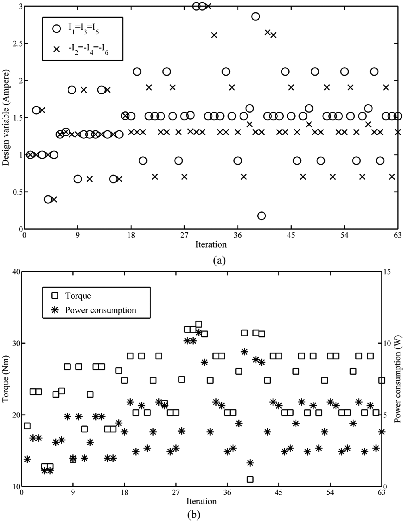
Optimization solution of the proposed MR brake when the three evenly spaced coils are a group: (a) design variable and (b) torque and power consumption.
Figure 11 shows the optimal solution of the proposed MR brake when all the six are applied an identical current, and the current in each coil is opposite to that of its two adjacent coils. Only an input current (

Optimization solution of the proposed MR brake when all the six coils are applied an identical current: (a) design variable and (b) torque and power consumption.
The above results show that different configurations of coils and input currents could result in a same observed torque. However, the power consumption of each configuration may not be the same. For a 25 N m desired torque, the minimum power consumption is 3.80 W when the six coils are applied 1.52, −1.30, 1.52, −1.30, 1.520, and −1.30 A, respectively. This optimization can serve as a reference for different designed torques. This is the advantage of the proposed MR brake configuration with several individual input currents.
Torque analysis in the proposed MR brake
In this section, different combinations of currents were analyzed to investigate the braking torque. When the current in every two opposite coils increases from 0 to 3 A with steps of 1 A, there are 64 combinations of input currents. Similarly, there are 16 combinations of input currents when the current in every three evenly spaced coils increases from 0 to 3 A with steps of 1 A. For the six coils applied an identical current which increases from 0.5 to 3 A with steps of 0.5 A, there are six values of braking torque.
Figure 12 shows the transmission torque of the proposed MR brake at different configurations of input currents. It can be seen that the generated torque basically depends on the configurations of coils and the magnitude of the input current. The maximum simulated torque is 36.17 N m when all six coils are applied 3 A input current.

Transmission torque of the proposed MR brake under different combinations of input currents.
To improve the transmission torque of MR brake devices, this article proposed a configuration of dual-gap MR brake with several poles which are surrounded by several coils. Therefore, a comparison of the designed MR brake proposed in this article with other typical MR transmission devices (Karakoc et al., 13 Liu et al., 30 LORD Corporation RD-2078-1, Rizzo et al. 11 and Shiao and Nguyen 27 ) presented in the state of art is necessary. Table 3 compares the design specifications of the proposed MR brake to some typical MR transmission devices in the literatures. To be clear, dynamic range is defined by maximum-to-minimum torque ratio, and the torque-to-volume ratio is defined by the ratio of maximum braking torque divided by the overall geometric volume of the brake. In addition, a useful index of the power consumption per unit transmission torque produced is proposed to measure the power consumption efficiency of the coils, which is defined by the ratio of maximum power consumption divided by the maximum transmission torque.
From Table 3, it can be seen that the multi-pole and dual-gap MR brake proposed in this research, with an amazing transmission torque of 2.88 × 10⁴ N m in 1 m3, has better transmission torque than the others shown in this table. In addition, this brake gives a maximum-to-minimum torque ratio of 19.5, and a power-to-torque ratio of 0.45. It can be concluded that the multi-pole and dual-gap MR brake can generate a high transmission torque in a given volume while maintaining low power consumption.
Conclusion
In this work, a novel multi-pole and dual-gap MR brake with individual input currents was proposed. Based on the finite element analysis, the magnetic field distribution in the gaps along the axial direction is uniform. Thus, the transmission torque can be improved by increasing the radial or the axial dimensions of MR fluid cylindrical surfaces flexibly. The simulations indicate that the proposed MR brake can generate 38.13 N m with 17 W power consumption when exploited up to its complete saturation. This provides 130% more torque in 1 m3 compared to the commercial brake, but the power consumption per unit transmission torque produced is only 12%. In addition, the advantage of this design (i.e. lower power consumption) is yet to be explored by individually controlling the input current in each coil.
Footnotes
Academic Editor: ZW Zhong
Declaration of conflicting interests
The author(s) declared no potential conflicts of interest with respect to the research, authorship, and/or publication of this article.
Funding
The author(s) disclosed receipt of the following financial support for the research, authorship, and/or publication of this article: This work was supported by Natural Science Foundation of Jiangsu Provincial College (grant no. 13KJB460010), Natural Science Foundation of China (grant no. 51305207), and Applied Basic Research Programs of Sichuan Province (grant no. 2012JY0085).