
Abstract
In rubber-wheeled road vehicles, the mechanical connection between steering wheel and front wheels provides steering-related feedback to the driver. The torque fed back to the driver through the steering linkages and steering wheel, which is called steering feel, helps the driver in controlling the vehicle. The torque feedback is reproduced via artificial methods in steer-by-wire systems due to the lack of mechanical connection. In this work, in order to minimize the physical workload and the lateral acceleration under the consideration of handling performance, optimization of a hysteresis-based steering feel has been studied. A 2-degree-of-freedom bicycle model based on the magic formula tire model has been used for simulations and hardware-in-the-loop experiments. A mathematical model is proposed in order to create an adaptive model-based optimization of the hysteresis parameters simultaneously while driving. A hardware-in-the-loop experimental setup has been used for the driving tests. The weave and the double-lane change tests have been performed with different drivers in order to demonstrate and quantify the optimization methods that are presented in this work.
Introduction
In classical road vehicles, the steering action is performed through the mechanical link between the front wheels and the steering wheel. When the front wheels are steered, a reaction torque, which is mainly based on the self-aligning torque (SAT), occurs, and the driver experiences the steering feel as a tactile feedback through steering wheel. Since the steering feel has a significant effect on the handling quality, it is stated as an essential feedback to the driver.1,2
The effect of steering torque feedback on the driver is not understood well since it has both objective and subjective aspects. Although there are studies in the literature in order to quantify the steering feel,3–9 they are still in their infancy.
In steer-by-wire (SBW) systems, elimination of the steering column results in the loss of mechanical connection between the front road wheels and steering wheel. A force-feedback system becomes indispensable for providing a steering feel to the driver. This feel is provided through an electrical motor attached to the steering wheel.10,11
Most of the studies in the literature mainly or partially use estimated SAT information to generate the conventional steering feel.12–14 Estimation of SAT brings some difficulties and complexity. Also, it is not suitable for lower velocities and when the vehicle is stationary. An additional approach seems to be needed to reproduce the steering feel in cases where the model based on the SAT is not applicable. Additionally, feeding the SAT back to the driver during the automatic control of road wheels would have a disturbing effect.
Based on the studies of steering feel in the literature, 15 the main reason influencing the steering feel is evident in the relation between the steering wheel angle and steering wheel torque feedback. In real driving tests, this relation has been identified as a curve resembling the Lissajous curve, 16 and used by Morita et al. 17 as a criterion, or mostly described as a hysteresis curve.18,19
The steering feel had to be designed so that it should reflect the maneuvering dynamics correctly. In the design of steering feel, the reflection of road wheels and road interaction to the driver is of crucial importance. In provision of this feedback, the steering torque feedback in the steering wheel system can be generated based on either the force signal from load cells attached to the rack or the mathematical model designed to produce the steering feel which is indispensably dependent on the estimation of tire parameters. When the cost, replacement, and calibrations of the load cell are taken into account, the estimation-based model would be more suitable.14,16,19
It is well known that the vehicle dynamics is dominated by tire dynamics. The experimental studies in the literature show that a lag characterizes the relation between the steering wheel angle and the torque reflected to the driver in the classical road vehicles. Mainly, the relaxation length in a tire is responsible for the lag, which delays the tire side forces. 20 Based on this hysteresis phenomenon, a steering feel model is designed to characterize a lag effect using the Bouc–Wen hysteresis model in a recent work. 21 In our study, we used and optimized this steering feel model.
There is still no general and sufficient model for designing the steering feel in the literature. This is still an ongoing research topic, yet we introduce a new approach in terms of designing the steering feel which pays attention to physical workload. Although there are a few works mentioning the physical workload, such as Tajima et al., 22 none of them considers it as a design parameter. Besides, there is no general mathematical definition of the physical workload. In this study, the physical workload is expressed by a new mathematical formula, and it is considered as a design parameter for creating the optimum steering feel through the hysteresis-based model approach. 23
This design approach aims to reduce the physical workload while satisfying the vehicle’s safety and sufficient handling performance. Another important criterion in this approach is the lateral acceleration. In order to provide safe and comfortable driving, the lateral acceleration should be kept to a minimum.
In brief, this study introduces an optimum steering feel design based on a hysteresis model, in which the driving quality is increased, and at the same time, the physical workload is decreased. The optimization of hysteresis-based steering feel model is fulfilled with two approaches, passive and active optimization. On one hand, the static (passive) optimization suggests to use the optimum values of the parameters that are constitutive for the hysteresis-based model. On the other hand, the online (active) optimization updates the optimum values of these parameters at every instant of the driving. To test the performances of the steering feel models, hardware-in-the-loop (HIL) simulation experiments with human drivers have been performed. The magic formula tire model is used,24,25 in a bicycle model, 26 because of their simplicity and wide acceptance. Two case studies based on standard test procedures have been presented: the weave test and the double-lane change test. The performance of a vehicle with the online optimized hysteresis-based steering feel model has been compared with the same vehicle having both the static optimized hysteresis-based steering feel and a SAT-based model. The reason for selecting the SAT-based model is that it is the main factor in generation of the steering feel in conventional vehicles. Thus, a realistic comparison could have been done.
The remainder of this article is organized as follows: section “Wheel dynamics and steering feel” introduces the hysteresis-based steering feel model and the vehicle dynamics. Section “Optimization strategies for designing the steering feel” demonstrates the static and online optimization. The HIL experimental setup is shown in section “HIL experimental setup.” Section “Results” discusses the results and summarizes this work.
Wheel dynamics and steering feel
The overall system dynamics includes the tire model, the bicycle model, and the steering feel model. The input of the overall system is the steering wheel angle applied by the driver where the output is the global position of the vehicle. The global transformation is a mathematical tool that is being used in order to transform the local variables to global ones. The global variables are simultaneously transferred to HIL virtual environment. The speed of the vehicle has been kept constant in all experiments and simulations.
In the HIL simulations, the driver’s steering wheel input has been acquired by an encoder. This input angle has been fed to the vehicle dynamics, and the calculated torque is fed back to the steering wheel through a servo motor. Note that although the mechanical and viscous effects contribute to the steering feel in conventional vehicles, they do not play an essential role in the generation of steering feel and do not involve information regarding the dynamics of vehicle. Hence, their effects are not considered in the models of steering feel. Two different models of steering feel are addressed in this study: the SAT-based and the hysteresis-based models. The schematics and the details of the HIL experimental setup are given in the further sections.
Tire model
A well-known and widely used semi-empirical tire model to calculate the tire forces and moments is the magic formula. Once the tire forces were obtained, a 2-degree-of-freedom dynamic model for lateral vehicle motion was developed using the bicycle model. The nominal values of a passenger car have been used for vehicle dynamics. The parameters of the vehicle were taken from a large front wheel drive saloon car. 27 The parameters of the tire were calculated by referring to formulations and tables given in Wong. 28 A simulation model has been created through MATLAB or Simulink™ environment. In order to keep the text concise, values of tire parameters are omitted. The reader is referred to Genta 27 and Wong 28 for the detailed tire model and parameter values.
SAT
The steering feel occurs as a result of the tire–road interaction during the steering of front wheels. The SAT plays the main role in generation of the steering feel in conventional vehicles. To calculate the SAT and the pneumatic trail, the magic formula tire model was used with the empirical parameters given in Wong. 28
The SAT has been used as a reference for three purposes: The first is to help in understanding the steering feel characteristic of a classical vehicle. The second is to use in determining the default values of the hysteresis parameters. The last is to clarify and identify the performance of optimized hysteresis-based models.
Hysteresis-based steering feel model
Bouc–Wen model of hysteresis was introduced by Bouc
29
and generalized by Wen.
30
This model describes the output restoring force to the input displacement in the form of a first-order nonlinear differential equation. The nonlinear hysteretic behavior of a physical system can be described as a map


where A, B, D, n, α, β, and γ are the parameters controlling the shape of hysteresis loop. Another model exactly equivalent to this standard model is preferred since it needs the identification of less parameters. By defining
with an initial condition

the model can be rewritten to form the normalized Bouc–Wen model.
In this study, we use a hysteresis-based steering feel model proposed by Arslan.
21
Based on the normalized Bouc–Wen model (see aforementioned studies for details of the model), a new hysteresis-based steering feel model for a road vehicle was built by adding the speed dependency. It is clear that as in power-assisted steering systems, the speed must be employed in the generation of steering feel. For this purpose, the parameter


where
Optimization strategies for designing the steering feel
In this section, two approaches on the design of steering feel are discussed: the static optimization and the online optimization. The static optimization yields the optimum values of parameters of the hysteresis-based model for the given criteria. The online optimization produces the optimum values of parameters, which are redefined as the time-dependent functions of vehicle dynamics and some measures, during the steering of a vehicle. The reason behind studying the online optimization approach is to create an adaptive model-based optimization on the vehicle dynamics while minimizing the given performance criteria. The unique approach of this online model is to reevaluate the optimum steering feel value at every instant of driving.
As described in the previous section, the hysteresis-based model includes five constant coefficient parameters to form the hysteresis curve. These parameters have different effects on the form of the curve and, as a result, on the steering feel. Since the main objective is to design an optimized model for the steering feel, optimum values of these parameters are sought.
In order to find optimum values of the parameters of the hysteresis-based model, we defined the physical workload, the lateral acceleration, and the vehicle’s path following performance as the performance criteria. In evaluating the steering response of a vehicle, the lateral acceleration is a commonly used parameter. By selecting the physical workload as another performance criterion, it was possible to make a comparison between the models from the exerted energy of human driver’s point of view. Thus, we have shown that the driver using the system with hysteresis-based model has not exerted more force than that of the system with the SAT-based model. Also, the workload has been used as a measure to show how a driving task can be completed with less effort by selecting the parameters of the hysteresis-based model.
Physical workload
Although there are a few suggestions on the calculation of physical workload in the literature, there has been no general and widely accepted model so far. We suggest a formula based on the formula in Arslan
21
and Kirli and Arslan
23
for the physical workload

where
Lateral acceleration
Lateral acceleration is the acceleration along the Y-axis with respect to the body fixed coordinate system. The driving comfort is directly influenced by the lateral acceleration. We have assumed that the driving comfort improves as the lateral acceleration decreases since the lateral acceleration is a disturbance to the driver and passengers.
Vehicle’s path following performance
One of the most important objectives of vehicle control systems is to follow the reference path. Since the steering feel affects the dynamics of handling, we monitor the actual global position of the vehicle and compare it with the reference path.
The vehicle’s path following performance indicates the success rate of driver in following the desired path. For instance, as shown in Figures 4 and 9, a successful performance means to complete the slalom course between the cones which are located at 40-m intervals.
Note that if the five parameters of the hysteresis-based steering feel model are varied in such a way that the torque generated in the steering wheel decreases dramatically, eventually, the physical workload decreases and the vehicle’s path following performance increases in numerical simulations. It is worth noting that if the steering feel vanishes, not in simulations but in real driving or HIL simulations, the vehicle’s path following performance would deteriorate as discussed previously. Hence, in addition to the aforementioned optimization criteria, the torque generated in the steering wheel has always been monitored and compared with the SAT.
The first step of the optimization process is to understand the individual effect of each parameter on the performance criteria defined above. Therefore, open-loop simulations in which only the vehicle dynamics and hysteresis-based model are included have been performed. The results have been confirmed by the closed-loop experiments. The reference inputs have been designed to carry out the weave test and the double-lane change test according to the ISO 13674 and 3888-1.
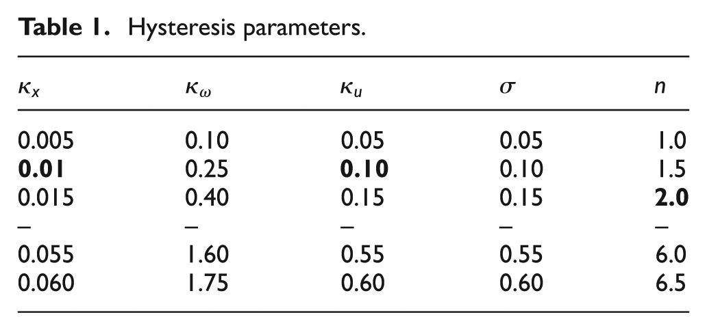
The speed has been kept at 60 km/h, and the value of each hysteresis parameter has been changed as shown in Table 1. When a parameter has been monitored, the other parameters have been kept constant at their predetermined values since the individual effects of all hysteresis parameters on the aforementioned performance criteria need to be identified.
Hysteresis parameters.
Effects of hysteresis parameters
The simulations have been performed for 12 different values of five parameters each and for two different reference inputs. The bold values are the default hysteresis values which are obtained to produce a similar output as of SAT. Overall 120 different scenarios have been investigated in simulation environment. For both the double-lane change test and the weave test, the results have been very similar to each other.
The effects of each parameter are summarized below. If we increase
n: The vehicle’s path following performance slightly decreases, the workload slightly increases, and the lateral acceleration does not change.
Static (passive) optimization of the steering feel
Once the effects of changing the parameters on the vehicle dynamics have been understood, optimum values of the parameters in terms of the criteria mentioned above can be sought. For this purpose, some simulations have been performed by changing two parameters simultaneously. One can change two parameters to increase the vehicle’s path following performance and decrease the physical workload by a correct selection of parameters. Thus, various simulations have been done to understand the effects of changing two parameters. Some selected results of these simulations are given in Table 2, where “↑” indicates increasing, “↓” indicates decreasing, and “≈” means no change or a slight change. The number of arrows indicates the intensity of change.
The effects of the hysteresis-based steering feel model parameters on the optimization criteria.
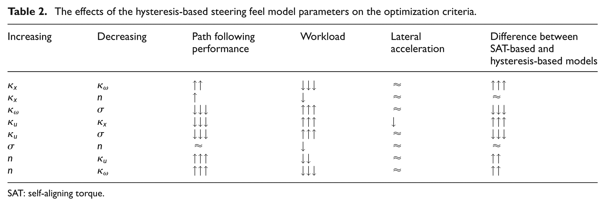
SAT: self-aligning torque.
As shown in Table 2, if
We chose the simulation method for static optimization since we need to understand the effects of each and every hysteresis-based model parameters on the performance criteria. The outcome which was the understanding of how to change these parameters to what end played a crucial role in designing the online optimization method.
Online (active) optimization of the steering feel
The constant optimum values of the hysteresis parameters are obtained by the static optimization method. These values increase the vehicle’s path following performance decrease the physical workload and the lateral acceleration. Yet these values are constants. At any instant of driving, there may be a different optimum value for each hysteresis parameter depending on the vehicle’s dynamics. Therefore, we have aimed to design an algorithm, based on real-time (online) data, coming from the vehicle dynamics. This projection led us to develop a mathematical model, in which the optimum values of hysteresis parameters are found simultaneously during the driving.
The online optimization calculates the optimum value for each hysteresis parameter using a mathematical model, in which the normalized SAT, the normalized hysteresis-based generated torque, and the yaw rate error (YRE) have been used as inputs (Figure 1). Online optimization considers the same performance criteria as in the static optimization.

Block diagram of the online optimization and inputs or outputs of the mathematical model.
All of the parameters used in the mathematical model of the online optimization are explained in Table 3. The default values of
Parameters used in the online optimization.

SAT: self-aligning torque.
Scaling factors of
The normalization gains of n,
YRE is defined as the difference between the desired yaw rate and the actual yaw rate. It is assumed that the vehicle’s path following performance increases as the actual yaw rate follows the desired yaw rate. If the YRE is increased, then the

The second goal of the proposed online optimization model is to create a steering feel that is sufficient enough to provide a realistic feel as well as to reduce the physical workload of the driver. This has been implemented by optimizing

In order to control this difference, through equation (9), the torque generated by the hysteresis-based model is increased. As a result, the difference has been reduced, although this reduction causes an increase in the physical workload. We have tried to balance the physical workload through equation (10). As


As mentioned in the static optimization method, if

Substituting n and

Instead of using the static optimized hysteresis parameters, through equations (8)–(12),
Both the static and online optimization methods have been compared and tested in computer simulations. In these simulations, the steering feel was generated by the SAT-based model and the hysteresis-based model (1) with default parameters, (2) with optimized static parameters, and (3) with online optimized parameters. According to the simulation results, the statically optimized hysteresis-based model performed better than the SAT-based model and the default hysteresis-based model. However, online optimized hysteresis-based model outperformed all steering feel models in terms of the handling, the physical workload, and the lateral acceleration.
HIL experimental setup
A HIL simulation environment has been designed to perform real driving experiments with human drivers. Even though the simulation results have already exhibited that the proposed online optimization’s performance has been better, in order to strengthen and prove our claims, we have done various driving tests with different human drivers through the HIL experimental setup. The MATLAB™ software package and dSPACETMDS1103 rapid controller prototyping board with the software ControlDesk and MotionDesk are used to build the HIL simulation environment.
For HIL simulations, a driving simulator with a steering wheel system has been used as shown in Figure 2. The physical system, the steering feel model, and the mathematical model of the vehicle were all configured and interfaced so as to constitute a closed loop. The steering system shown in Figure 2 mainly consists of the steering wheel and an electric motor attached to the steering wheel by a flanged connector. The NSK Megatorque direct drive motor, which is an AC servo motor with
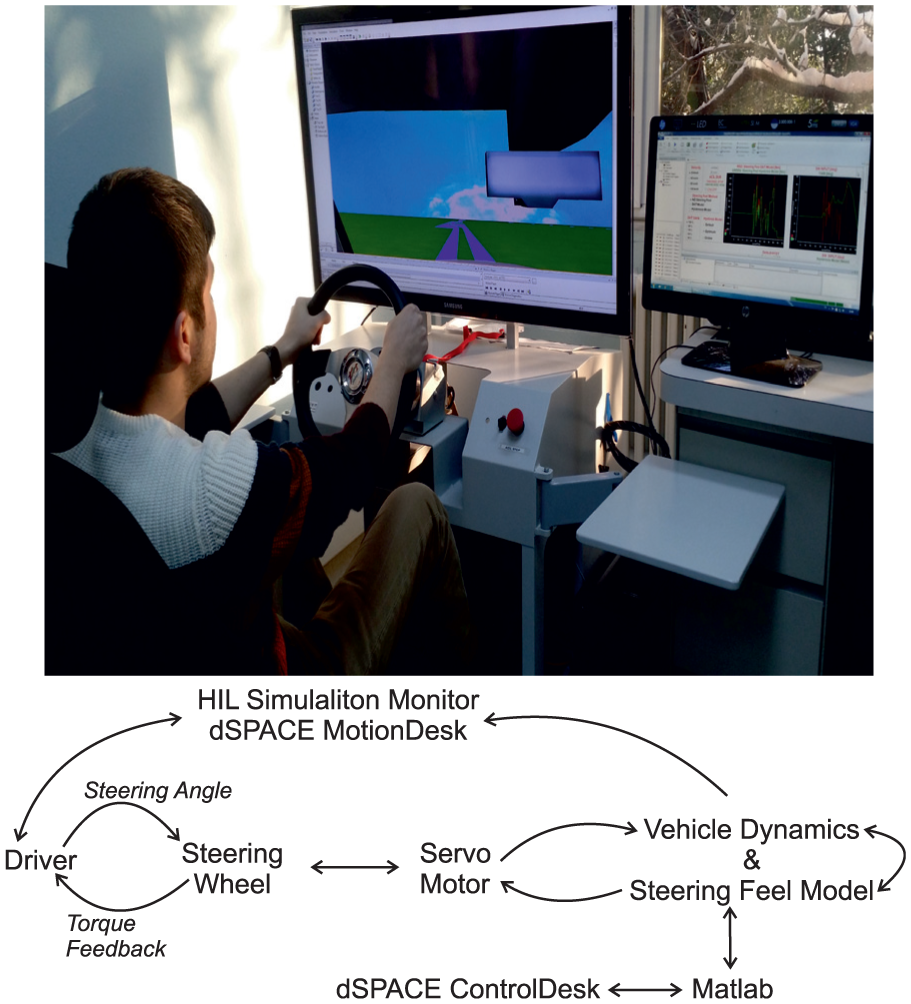
HIL experimental setup: actual picture while experimenting and block diagram of the system.
During the execution of this optimization study, the system has been subjected to different simulation scenarios, while the speed of the vehicle has been kept constant at 60 km/h. Therefore, in real experiments the drivers have been asked to complete the path at 50 and 80 km/h in order to corroborate our claims.
Testing strategy
The drivers have been expected to drive the vehicle in the graphical environment which is designed for the weave test and double-lane change test according to the ISO 13674 and 3888-1. Each driver has completed the path for three times. Then, they have taken a rest for a few minutes. After that, they have completed the path for three times again and have taken a rest. This loop has been repeated by all drivers. At each break time, the steering feel has been changed without informing the driver. The way we have changed the steering feel model and the sequence have also been different for all drivers in order to prevent any bias. Overall, three drivers have completed the path for three different steering feel models at two different speeds.
Results
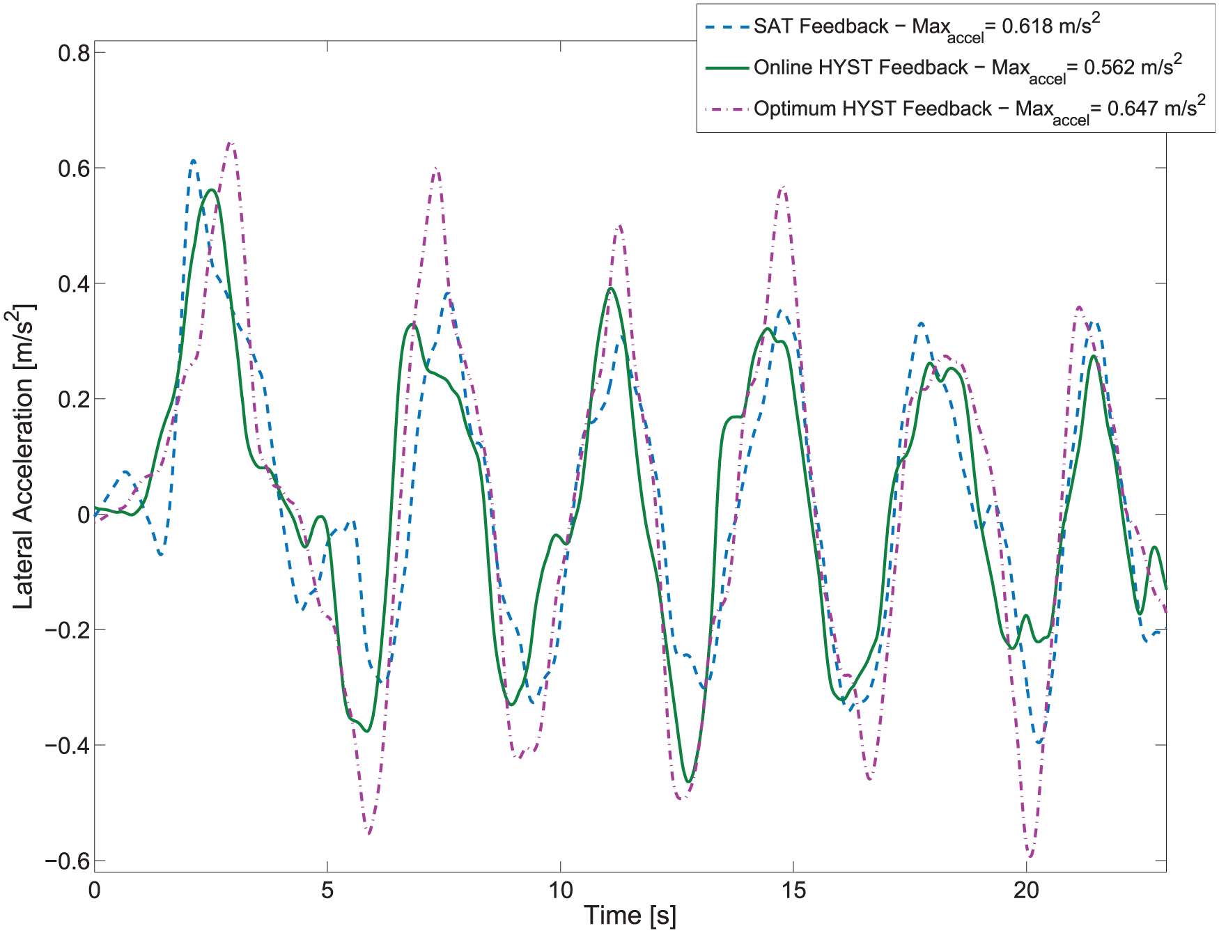
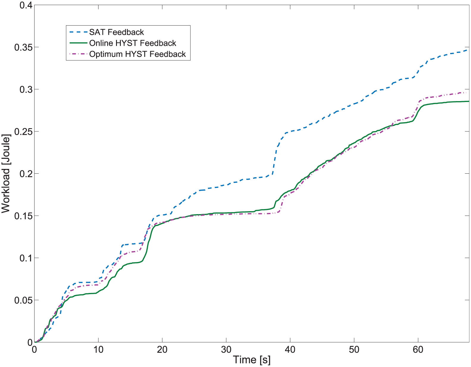
The results of the performed tests are given in Figures 3–12. In these figures, SAT Feedback, Optimum HYST Feedback, and Online HYST Feedback represent that the steering feel feedback is generated by the SAT-based model, static optimized hysteresis-based model, and online optimized hysteresis-based model, respectively.

Vehicle position in the double-lane change test at 50 km/h.

Vehicle position in the weave test at 50 km/h.

The hysteresis loop at 50 km/h for the weave test.

Time histories of the lateral acceleration at 50 km/h for the weave test.

The physical workload at 50 km/h.

Vehicle position in the double-lane change test at 80 km/h.

Vehicle position in the weave test at 80 km/h.

The hysteresis loop at 80 km/h for the weave test.
Time histories of the lateral acceleration at 80 km/h for the weave test.
The physical workload at 80 km/h.
In the tests where the speed is 50 km/h, the drivers have performed better in terms of path following when the steering feel is generated through the SAT-based model and the online optimized hysteresis-based model as shown in Figures 3 and 4. However, the SAT-based model has led to more workload and lateral acceleration (Figures 6 and 7). Static optimized hysteresis model appears better than the SAT-based model in terms of workload and lateral acceleration. However, the online optimization method has outperformed the other methods in all aspects.
In the tests where the speed is 80 km/h, the drivers performed slightly better in terms of path following in the double-lane change test when the steering feel is generated by the statically optimized hysteresis-based model as shown in Figure 8. However, performances of the drivers have been better for weave test when the steering feel is created with the online method (Figure 9). Besides, the online optimization has reduced the workload and the lateral acceleration as well (Figures 11 and 12). Static optimized hysteresis-based model appears slightly better than the online optimization-based model for the double-lane change test, but overall, the online optimization method outperforms the other methods in total.
One of the major handling performance factors of the steering feel model is the on-center performance. The on-center performance is defined as the gradient of the steering wheel input and the steering wheel torque under the weave test.3,9 On-center performance increases as the ratio of the generated steering torque to steering wheel input increases. The gradients in Figures 5 and 10 are calculated as follows: for 50 km/h, 0.014, 0.012, and 0.016 N m/° and for 80 km/h, 0.024, 0.022, and 0.030 N m/°, for the SAT-based model, the optimum hysteresis-based model, and the online hysteresis-based model, respectively.
The results of all performance criteria are given in Figure 13. The radar charts in Figure 13 demonstrate the performances of the steering feel models for 50 and 80 km/h. The success of each model for every criterion is measured as the closeness to the edge of those criteria. The overall success of each model is measured through the colored area of each contour. It is understood that
For speed 50 km/h, the SAT-based model performs well for two performance criteria;
For speed 50 km/h, the optimum hysteresis-based model performs well for one performance criterion;
For speed 50 km/h, the online hysteresis-based model performs well for all performance criteria;
For speed 80 km/h, the SAT-based model performs well for one performance criterion;
For speed 80 km/h, the optimum hysteresis-based model performs well for two performance criteria;
For speed 80 km/h, the online hysteresis-based model performs well for four performance criteria.
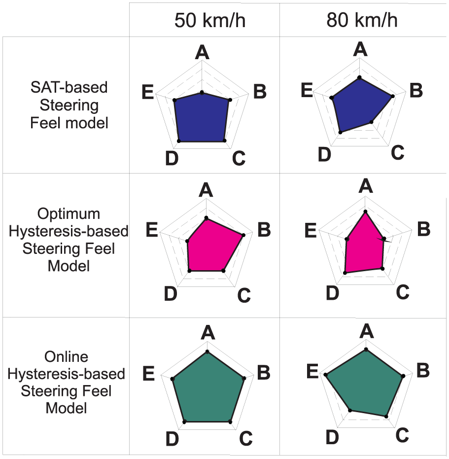
Comparisons between the steering feel models.
In HIL simulations, three different drivers have been asked to perform the driving. In these tests, all of the steering feel models that are used in this study have been limited to maximum 1 N m steering torque value in order to enable an accurate comparison between the models for clarifying our claim on reducing the physical workload. The HIL simulations showed that even if the steering feel torque is below 1 N m, the drivers were able to drive the vehicle successfully. In total, each steering feel model has been tested for approximately 150 km at two different speeds. The suggested online steering feel model has exhibited better results for 50- and for 80-km/h tests for all performance criteria. The HIL simulations indicate that any driver may perform a better driving when the steering feel is generated by the online optimized hysteresis-based model.
Conclusion
In this work, in order to minimize the physical workload and the lateral acceleration under the consideration of handling performance, optimization of the hysteresis-based steering feel has been studied. Three different steering feel models have been designed and compared to each other for predetermined performance criteria. The first and the second performance criteria are the vehicle’s path following performance in the weave test and in the double-lane change test. The third performance criterion is the physical workload, where the less workload indicates a better performance. The fourth performance criterion is the lateral acceleration, where the less lateral acceleration indicates a safe and comfortable drive. An additional approach is the on-center handling where the driver recognizes that the vehicle is straight in the longitudinal direction, and the steering wheel input is zero. Through these criteria, we have demonstrated that the suggested online optimized hysteresis-based steering feel model has performed better.
During a driving, the optimum steering feel value do change due to the dynamics of the vehicle at that instant. The optimum steering feel value is generated by reevaluating the hysteresis parameters at every instant of the driving. Open- and closed-loop numerical simulations have been performed, and the effects of each hysteresis parameters on the steering feel have been investigated. In conclusion, a mathematical model, to calculate the optimum hysteresis parameters, is obtained. In addition, HIL simulations with different human drivers have been performed for different scenarios. Finally, the advantages of the suggested online optimized hysteresis-based steering feel model have been presented by the outcomes of these HIL simulations.
Footnotes
Academic Editor: Hamid Taghavifar
Declaration of conflicting interests
The author(s) declared no potential conflicts of interest with respect to the research, authorship, and/or publication of this article.
Funding
The author(s) disclosed receipt of the following financial support for the research, authorship, and/or publication of this article: This research is principally funded by The European Union, Marie Curie Actions-Support for training and career development of researcher (Project ID: PCIG09-GA-2011-294231—SteeringFeelSBW).