
Abstract
The driving mode by servo motor is a new driving mode and can realize oscillations of continuous casting mold as expected. The oscillation system of continuous casting mold driven by servo motor is a complicated nonlinear system. Therefore, it is necessary to establish an accurate model for the system before performing simulation experiments. Based on the oscillation platform system of continuous casting mold driven by servo motor in the laboratory, the nonlinear models of servo motor speed system and mechanical transmission parts were respectively established and the viscous friction coefficient, moment of inertia, and load torque were identified. Then, the nonlinear mathematical model of the whole oscillation platform of continuous casting mold driven by servo motor was obtained. The comparison results between the simulated output curves of established model and the measured output curves of actual system under the same input signals indicated that the simulated curves were almost in accord with the measured curves. Therefore, the proposed model can reflect the capabilities of practical system and lay a good foundation for subsequent research on simulation experiments and accurate control of continuous casting mold oscillation driven by servo motor.
Keywords
Introduction
Continuous casting is an important step in steel production. Continuous casting mold is forming equipment and its properties are vital to slab quality and production of continuous casting machine.1,2
The evolution of the continuous casting mold oscillation technology 3 is mainly divided into two stages: the development stage of oscillation waveform and the development stage of oscillation device. 4 In the early stage, rectangular oscillation was adopted, and then gradually developed into trapezoidal oscillation, sinusoidal oscillation, and non-sinusoidal oscillation.5–7 Li et al. 8 introduced the non-sinusoidal oscillation regulation and analyzed the advantage of non-sinusoidal oscillation compared to sinusoidal oscillation. The most remarkable feature of non-sinusoidal oscillation is that the rising time is much longer than lowering time, thus increasing casting speed and improving slab quality. The non-sinusoidal oscillation of continuous casting mold is one of the key technologies for efficient continuous casting.9,10
Three driving modes, including mechanical drive, hydraulic drive, and servo electric-cylinder drive, are mainly adopted to drive non-sinusoidal oscillation of continuous casting mold in industrial fields. Non-sinusoidal oscillation devices driven by machine, such as non-circular gear (ellipse gear) device 11 and anti-parallel four-bar linkage device,12,13 have been developed in China. Mold non-sinusoidal oscillation device driven by electro-hydraulic servo system has been widely applied at home and abroad.14,15
In this article, servo motor was adopted to realize non-sinusoidal/sinusoidal oscillation of continuous casting mold.16,17 Servo motor replaced normal AC motor 18 to run continuously at single-direction variable angular velocity and realize oscillation through reducer and eccentric shaft linkage mechanism. Based on the above principles, we set up the oscillation platform system of continuous casting mold driven by servo motor in the laboratory. After previous studies on non-sinusoidal waveform, parameter selection principle,19,20 and relevant modeling methods,21,22 we established a mathematical model to describe the properties of the system better for further simulation experiments of continuous casting mold.
In this article, we first introduced the overall structure of the system comprising servo motor speed system and mechanical transmission parts, and then established the nonlinear models of these two parts, and identified the viscous friction coefficient, moment of inertia, and load torque with the least square method to obtain the relatively accurate mechanism model of the whole continuous casting mold oscillation system. Finally, we compared the simulated output curves of the established model with the actual system output curves under the same input signals, analyzed the errors, and validated the effectiveness of the model.
Structure of oscillation platform of continuous casting mold driven by servo motor
Figure 1 shows the speed control cabinet and oscillation platform of continuous casting mold in the laboratory. The servo motor is permanent magnet synchronous motor (Siemens 1FT6134-6SB71). The servo motor and corresponding servo drive unit S120 forms the speed loop and current loop.

Speed control cabinet and oscillation platform of continuous casting mold.
Figure 2 shows the structure diagram of oscillation platform of continuous casting mold driven by servo motor composed of servo motor, coupling, reducer, eccentric shaft, linkage, mold, shaker arm, and so on. The control structure is shown in Figure 3. The servo motor speed system is connected with mechanical transmission parts through the reducer.

Structure diagram of oscillation platform of continuous casting mold driven by servo motor.

Control structure of the oscillation platform of continuous casting mold driven by servo motor.
In Figure 3, the given speed of servo motor
Modeling for oscillation platform of continuous casting mold driven by servo motor
Modeling of the servo motor system and parameter identification
According to the vector control principle, in the

where
The parameters of servo motor are provided in Table 1. Moment of inertia of the motor itself is
Parameters of servo motor.

The identification process of parameters J and B is described below.
The motor torque equation is expressed as
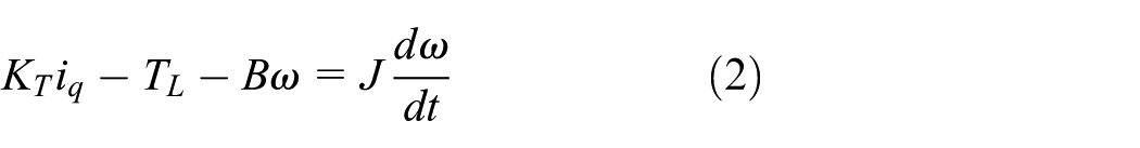
The characteristic curves of load torque are basically the same at two similar rotation speeds. Therefore, equation (2) can be transformed into equation (3)

where
Then, equation (3) is converted into equation (4)

According to the least square estimation theory, the estimated values of J and B are

The expected speed of motor is expressed as

where reduction ratio
The parameter identification process is introduced as follows:
Viscous friction coefficient can be calculated with the motor current (current of q axis) data (shown in Figure 4) of two similar constant speed (sinusoidal oscillation,
On the basis of viscous friction coefficient value, total moment of inertia is calculated by motor current data (shown as Figure 5) of two similar time-varying speed (non-sinusoidal oscillation,
The estimated value of load torque

Motor currents under two similar constant speeds: (a)
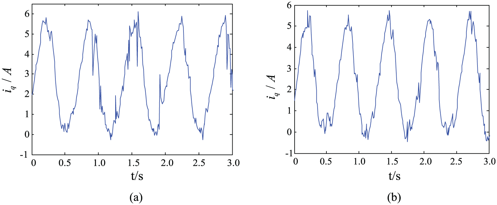
Motor currents under two similar time-varying speeds: (a)
The controllers of motor speed, q axis current and d axis current, are proportional–integral (PI) controllers (Siemens S120). The control type is

where
By parameter self-tuning of servo motor controller S120, the control parameters are obtained (Table 2).
Control parameters of servo motor controller S120.

Nonlinear model of mechanical transmission parts
Mechanical transmission parts mainly include eccentric shaft and linkage oscillation platform. Models of mechanical transmission parts are established as follows.
Eccentric shaft and linkage structure are shown in Figure 6(a). O is the center of outer circle, and

Eccentric shaft: (a) structural diagram of eccentric shaft and (b) principle diagram of eccentric shaft.
In Figure 6(b), the angle between eccentric distance

For the mold oscillation platform, the mold lies between Point C and Point D, and Point C performs approximately circular motion relative to the fixed Point D. According to the leverage principle, the displacement of mold is approximately proportional to the displacement of Point C. In Figure 1, the horizontal distance between Point C and Point D is about

where the approximate proportion coefficient is
Nonlinear model of continuous casting mold platform
The system input is u (generally corresponding to

Structure diagram of continuous casting mold vibration platform driven by servo motor.
Simulation experiments and error analyses
Simulation experiments
In order to verify the model, we adopted the same several typical input signals in the mathematical model and actual system, and analyzed the output curves.
First, we conducted relevant experiments with the oscillation platform of continuous casting mold in the laboratory. We developed the data acquisition program in the PC equipped with Siemens Step7 software, and used WinCC to inquire and monitor data. We acquired the mold displacement to PLC with displacement transducer and uploaded the data to PC for processing. Different motor speeds were set via the input terminal of actual system (the input signal is constant speed and time-varying speed). Then, we collected the data and obtained the curves of mold displacement at the output terminal.
Then, we used MATLAB/Simulink tools to conduct simulation. The same expected speed was adopted in the actual system and experimental model. The mold displacement was obtained with the model established in the article (simulation time was 3 s and the step size was 0.004 s).
The given displacement waveform function developed by DEMAG corporation is expressed as

Figure 8 shows the output curves of the model and actual system under the constant speed (f = 90 times/min and
Output curves of the model and actual system under the constant speed: (a)
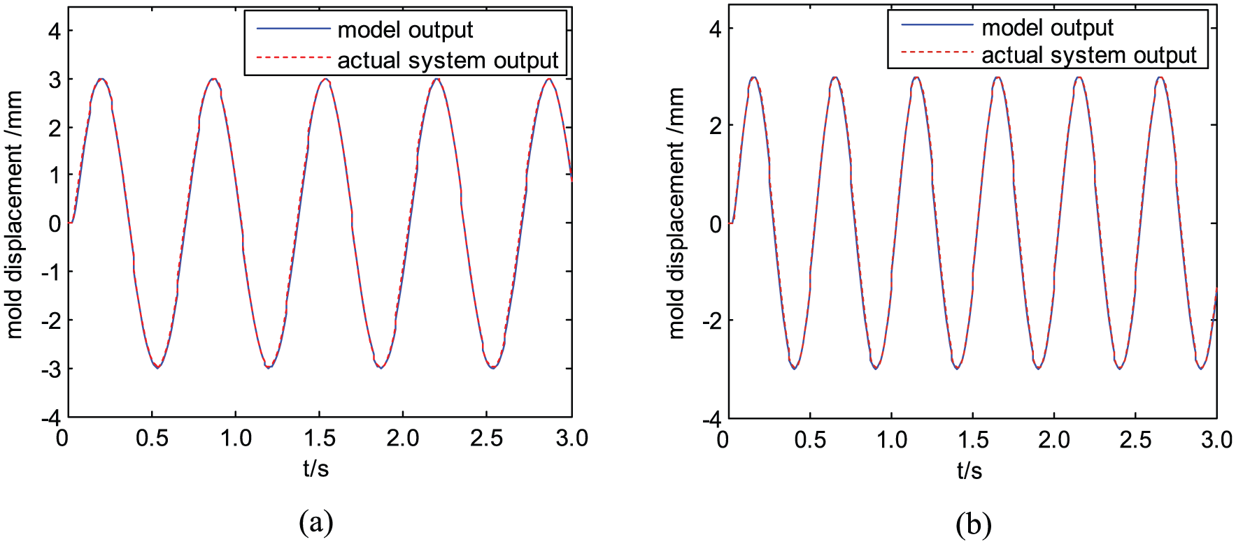
Figure 9 shows the output curves of model and actual system under the time-varying speed (f = 90 times/min and

Output curves of the model and actual system under the time-varying speed: (a)
As shown in Figure 8 and 9, the output curves of the simulation model and actual system are almost coincident with each other and show the better fitting results, which indicates that the established mathematical model in this article is close to the actual system.
Error analyses
The model error is discussed below. The error curves (Figures 10 and 11), respectively, corresponds to the curves in Figures 8 and 9. Relative error E is defined as

where

Error curves under the constant speed: (a)

Error curves under the time-varying speed: (a)
In the error curves, we can conclude that the model error is within 5%. The higher the frequency, the larger the error, because the higher frequency has the strong impact on the system response. The error analyses indicate that the established model in the article is reasonable and accurate.
Conclusion
With the oscillation platform of continuous casting mold driven by servo motor in the laboratory, an entire nonlinear system model, including servo motor speed system and mechanical transmission part, is established. Meanwhile, the viscous friction coefficient, moment of inertia, and load torque are identified.
Under the same input signal, the simulation output curves coincide with the actual output curves well, indicating the effectiveness of the established model.
The model error is less than 5%, indicating the effectiveness of the model.
Footnotes
Academic Editor: Liyuan Sheng
Declaration of conflicting interests
The author(s) declared no potential conflicts of interest with respect to the research, authorship, and/or publication of this article.
Funding
The author(s) disclosed receipt of the following financial support for the research, authorship, and/or publication of this article: Item sponsored by the Natural Science Foundation of China and Baosteel Group Co., Ltd. (grant no. U1260203); Natural Science Foundation of Hebei Province (grant nos. F2015203400 and F2016203263); Doctor Foundation of Yanshan University (grant no. B960); the Cultivation Program Project for Leading Talent of innovation team in Colleges and universities of Hebei Province (grant no. LJRC013).