
Abstract
This study proposes a new type of magnetic gear, namely, the electromechanical integrated magnetic gear, that integrates the traditional field-modulated magnetic gear, drive, and control. The topology and operating principle of the electromechanical integrated magnetic gear are described in detail in this article, and the constraints of parameter design and speed ratio of electromechanical integrated magnetic gear are presented. Moreover, magnetic field distribution is analyzed with the finite element method. Subsequently, the harmonics of the magnetic field and the electromagnetic torque are calculated. The static torques on all the components are exhibited by finite element method and torque test. The effects of the design parameters on the torques and the torque densities are discussed, and the results show that electromechanical integrated magnetic gear has a high speed ratio and can generate a high torque at low speed. The maximum torques are affected by air-gap thickness and other parameters.
Introduction
Mechanical gear boxes (MGBs) are extensively used to produce and convert power in the wind, vehicular, aerospace, and other fields; MGBs also play significant roles in the mechanical industry. However, gear tooth contact mechanisms inevitably cause associated wear, vibration and noise, lubrication and friction, and energy losses. These disadvantages have significantly limited the applications of MGBs. Noncontact magnetic gears have received much scholarly attention because of their many advantages; in particular, magnetic gears with high output torque and high torque density have been investigated extensively.1,2
The field-modulated magnetic gear (FMMG) was proposed by K Atallah in 2001. This gear can realize equal magnetic pole coupling with different numbers of permanent magnet (PM) pole-pairs. FMMG adopts a coaxial topology and exceeds the limit of the traditional magnetic gears that adopt the parallel shaft topology; therefore, FMMG significantly improves PM utilization rate. So, FMMG can generate a high torque and a high torque density. The transmission capacity of FMMG is comparable with that of MGBs. 3 FMMG can be extensively used in the medical, vehicular, navigational, aerospace, and other fields because of its advantages, such as free from lubrication, little noise, and inherent overload protection.4–6
Over the past decade, many studies have been conducted on FMMG that focus on aspects such as the transmission mechanism,3,4 transmission efficiency, 7 structural optimization, 8 component eccentricities, 9 mechanical deflection, 10 positioning control, 11 and dynamics. 12 In particular, parameter optimization and cogging torque13,14 have been discussed in detail. Consequently, the transmission performance and transmission capacity of FMMG have improved significantly. Various new types of magnetic gears were proposed as well. Atallah and colleagues15,16 developed high-performance linear magnetic gear and a high-performance axial-field magnetic gears that supplement the FMMG topology. Afterward, a continuously variable magnetic gear was established by changing the inner rotor structure. 17 Moreover, Rashidi and Pishdad 18 presented an integrated multispeed magnetic gear with a high transmission ratio. All the aforementioned magnetic gears adopt a coaxial topology. Liu et al. developed a magnetic gear with intersecting axes based on a field-modulated mechanism. This gear overcomes the limitations of the traditional intersecting axis magnetic gear, which exhibits low output torques and torque densities. 19 Furthermore, many types of direct current and alternating current PM motors were proposed for extensive use in the electric vehicle and wind industries.20–22 These have significantly promoted the development of magnetic gears.
The coaxial topology of FMMG ensures that this gear can be readily integrated with electric machinery. Thus, this study proposes a new type of electromechanical integrated magnetic gear (EIMG) that integrates the FMMG, drive, and control. Unlike FMMG, EIMG follows a two-stage transmission process and displays a high speed ratio. As such, the latter has the advantages of a compact structure and controlled torque and speed. EIMG can generate a high torque at low speed and has an extensive application prospect. The operating principle of this gear and the effects of design parameters on output torque are important in accelerating EIMG implementation in industries.
EIMG operating principle
Topology and constraints
The EIMG shown in Figure 1 is composed of the inner stator, inner and outer ferromagnetic pole-pieces (FP), the inner rotor, and the outer stator (or rotor). All the components are concentric, and EIMG has four air-gaps. Three-phase coils are arranged in the groove of the inner stator; meanwhile, PMs are positioned uniformly on the inner surface of the outer stator (rotor) and inner and outer surfaces of the inner rotor. The inner and outer ferromagneitc pole-pieceses (FPs) are composed of permeable and nonpermeable magnetic materials layered at regular intervals. The FPs modulate the magnetic fields in the two air-gaps beside FPs in order to make the number of pole-pairs of the PMs on the inner and outer rotors agree with the number of pole-pairs of the space harmonic flux density of the air-gaps.

Topology of the electromechanical integrated magnetic gear (EIMG).
To couple components with different numbers of pole-pairs of PM or electrical current, the following constraint relations must be met

where N1 is the number of pole-pairs of three-phase alternating electrical current in the coils on the inner stator; N2, N3, and N4 are the numbers of pole-pairs of PMs on the inner and outer surfaces of the inner rotor and inner surface of the outer stator, respectively; and NIf and Nof are the number of pole-pairs related to the pole-pieces of the inner and outer FPs, respectively.
Operating principle
When the three-phase alternating current in the coils on the inner stator is activated, a rotary magnetic field is generated with the main harmonic PIs and modulated by the inner FP. Here, the PIs equals N1 because the number of pole-pairs of three-phase alternating electrical current in the coils on the inner stator is N1. Then, the main harmonic of the magnetic field in the second air-gap PI1 is determined. This harmonic is consistent with the number of pole-pairs of PMs on the inner surface of the inner rotor, N2. Consequently, the inner rotor can be actuated, and the first drive is achieved. When the inner rotor runs, the main harmonic of the magnetic field in the third air-gap PI2, which equals to N3, is modulated by the outer FP. As a result, the main harmonic number of the magnetic field in the fourth air-gap Pos is equal to the number of pole-pairs of PMs on the outer stator (or rotor), N4. When the outer FP is fixed, the outer rotor outputs speed and torque. When the outer rotor is fixed, it is called the outer stator, and the outer FP generates torque. Thus, the second drive is achieved.
The EIMG has a two-stage train and a high transmission ratio. As such, this gear exhibits a compact structure and simplifies the electromechanical drive system drastically. Output torque and speed are controlled; in addition, EIMG can generate a high torque at low speed and can be applied in the vehicular, chemical, and other fields.
Speed ratio
The speed ratio of the first drive can be calculated as follows

When the outer FP is fixed, the speed ratio of the second drive can be computed as follows

The general speed ratio of the EIMG system can be calculated as follows

When the outer rotor (or outer stator) is fixed, the speed ratio of the second drive can be determined as follows

Then, the general speed ratio can be calculated as follows

Speed
When the frequency of three-phase alternating currents is denoted by f, the output speed of the outer FP or the outer rotor can be computed as follows

Torque characteristics
Finite element model and magnetic field distribution
All components in the EIMG system are coupled by the magnetic field. When the outer stator is fixed, the two-dimensional finite element model (FEM) of the sample EIMG system shown in Table 1 can be generated. In this study, the inner stator is composed of silicon steel sheets. The back irons of the inner rotor and the outer stator all consist of Q235 steel. The permeable and nonpermeable magnetic materials of the inner and outer FPs are composed of 23TW250 and epikote, respectively; the material characteristics of the epikote are basically similar to air. The magnetic flux density (B) and magnetic field intensity (H) curve of the back iron of main components are shown in Figure 2. The remanence and coercivity of PMs on the inner rotor and outer stator are presented in Table 1 as well. Meanwhile, the magnetic circuits are linear and unsaturated; moreover, the grid divisions are manually set. Calculation can be accelerated by controlling grid refinement. The inner total number of grid of the FEM of EIMG system can be controlled by inside selection. The FEM and the initial grid model are depicted in Figure 3.
Parameters of the sample EIMG system.
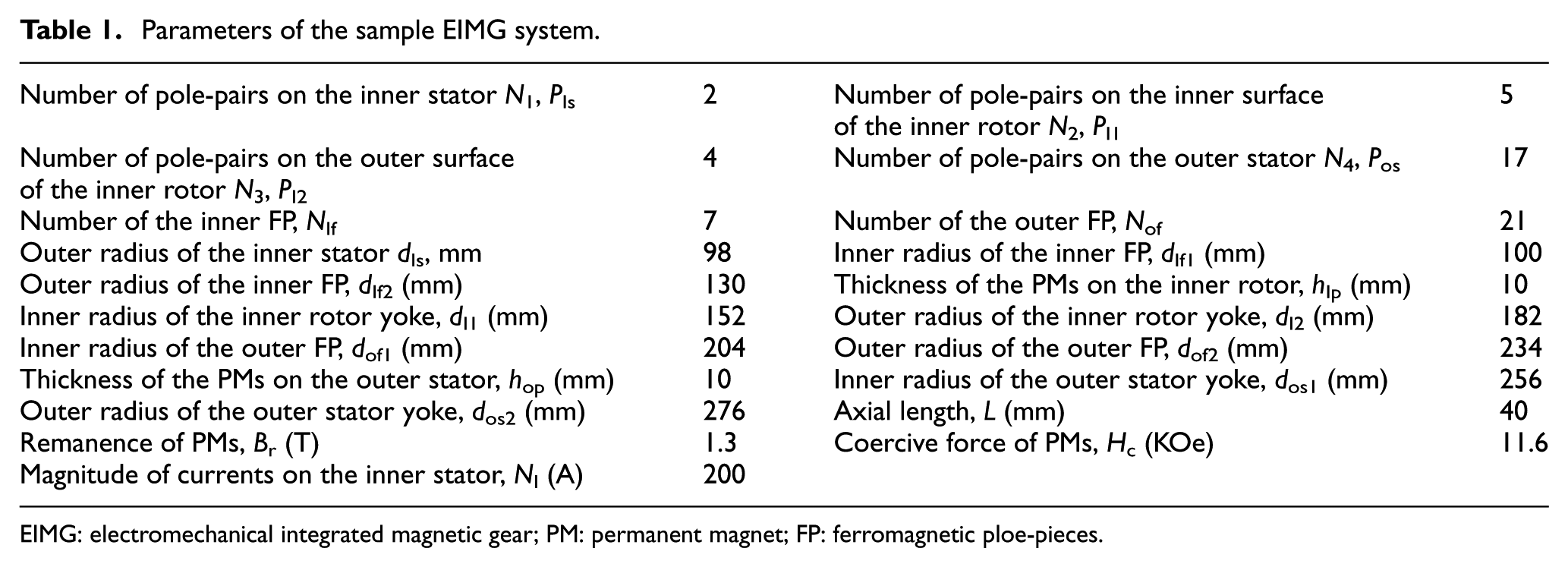
EIMG: electromechanical integrated magnetic gear; PM: permanent magnet; FP: ferromagnetic ploe-pieces.
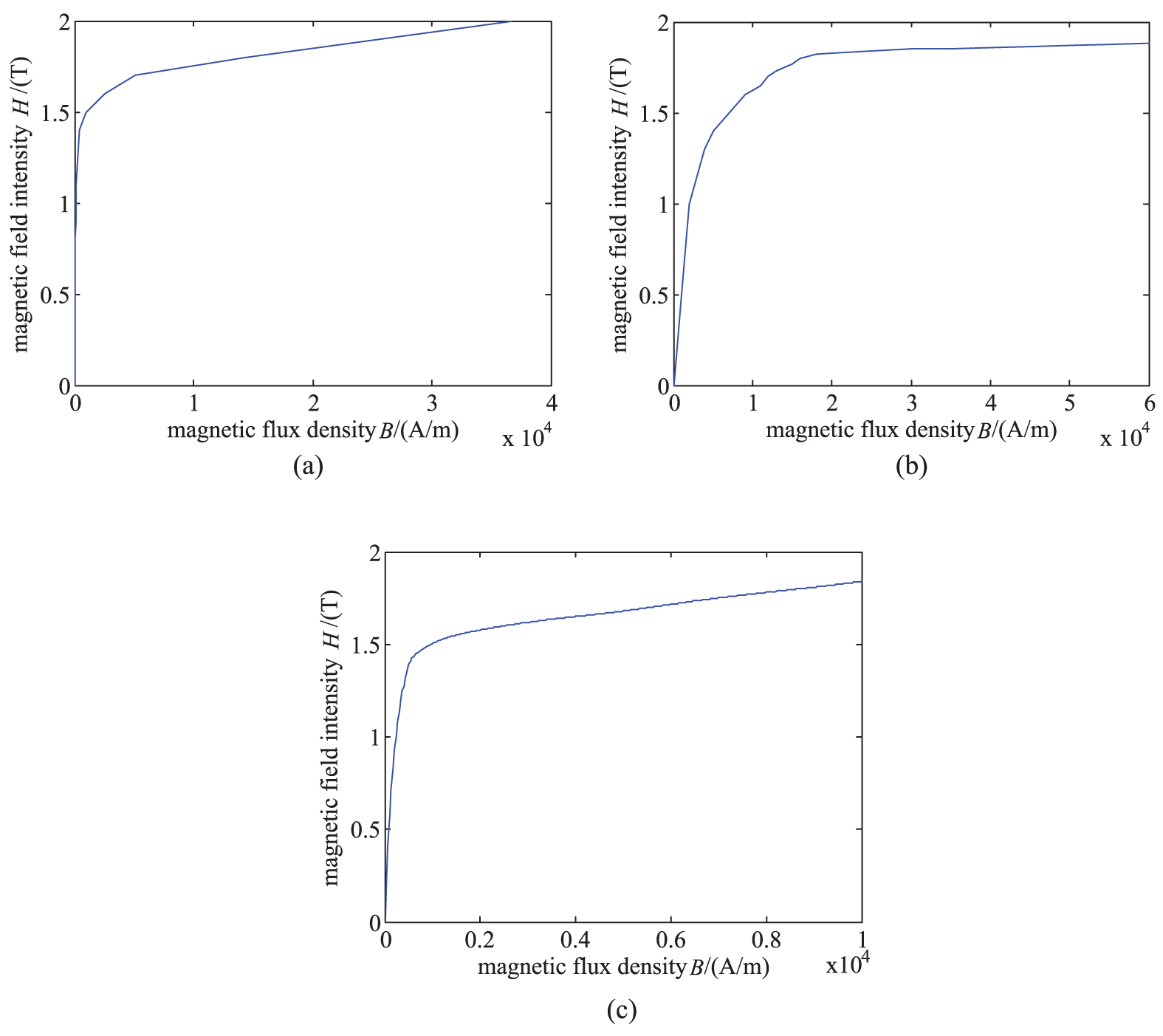
BH curves of the back iron of the main components: (a) back iron of the inner stator, (b) back iron of the inner rotor, and (c) back iron of the outer stator.

Finite element model (FEM) of the EIMG system: (a) two-dimensional FEM, (b) arrangements of PMs segments, and (c) initial grid model.
The meshes on the back iron of the inner rotor and the PMs on the inner rotor have common boundary nodes. The meshes on the back iron of the outer stator and the PMs on the outer stator have common boundary nodes. The meshes on the magnetic components and nonmagnetic components of the inner and outer FPs have common boundary nodes. But the middle positions of the air-gaps are not the common areas of the nodes. During running of the EIMG system, all unit nodes on the PMs and the back iron of the inner rotor rotate together as a rigid body. Similarly, the meshes on the magnetic components and nonmagnetic components of the outer FP rotate together as a rigid body. The magnetic reluctances of the air-gaps are larger, and the variation gradients of magnetic flux density are higher than those of the PMs and back irons. As such, the meshes of the air-gaps are denser than those of the other components. The magnetic field distribution is calculated by interpolations among the boundary nodes and is shown in Figure 4.
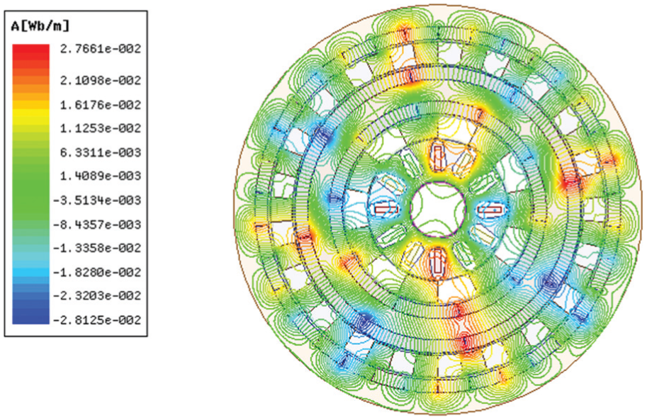
Magnetic field distribution of the EIMG system.
Figure 4 shows the three types of flux line distribution: (1) in the first and second drives, the magnetic flux lines close near the contact regions of the adjacent PMs. (2) Most of the magnetic flux lines that are generated by currents in the coils on the inner stator and the PMs on the inner surface of the inner rotor close through the inner stator, the inner FP, and the inner rotor. Thus, the first drive can be subject to the magnetic field coupling. Most of the magnetic flux lines that are generated by PMs on the outer surface of the inner rotor and the inner surface of the outer stator close through the inner rotor, the outer FP, and the outer stator. Therefore, the second drive can be subject to magnetic field coupling. (3) Several magnetic flux lines close through the first and second drives, that is, these flux lines cross all components. Thus, the magnetic coupling of the two drives is synergized.
When the phase angle of the first phase current on the inner stator is π/4 and the relative rotation angle between the inner rotor and the outer stator is π/8, the magnetic flux densities in the middle of the four air-gaps and the harmonics of radial magnetic flux density can be calculated, as depicted in Figures 5 and 6. In Figure 5, the magnetic flux densities, Br or Bt, will be negative when the angle between the magnetic field and the normal of a certain point is greater than π/2. Conversely, Br or Bt will be positive.

Magnetic flux densities in the middle of the air-gaps: (a) first air-gap, (b) second air-gap, (c) third air-gap, and (d) fourth air-gap.

Harmonics of magnetic flux densities in the middle of the air-gaps: (a) first air-gap, (b) second air-gap, (c) third air-gap, and (d) fourth air-gap.
Figures 5 and 6 indicate that there are multiple harmonics in the magnetic fields of all the air-gaps. The main harmonics of the magnetic fields are 2, 5, 4, and 17 in the first, second, third, and fourth air-gaps, respectively. These numbers are equal to the numbers of pole-pairs of the three-phase alternating current in the inner stator, PMs on the inner and outer surfaces of the inner rotor, and PMs on the inner surface of the outer stator, respectively. As such, equal pole-pairs can be coupled; furthermore, movement and torque can be outputted.
The harmonics of the electromagnetic coupling torques in the middle of all the air-gaps can be determined with the Maxwell stress tensor method and based on magnetic flux density. These numbers are exhibited in Figure 7.

Harmonics of the electromagnetic torques in the middle air-gaps: (a) first air-gap, (b) second air-gap, (c) third air-gap, and (d) fourth air-gap.
Figure 7 illustrates that a certain electromagnetic torque has only one harmonic component. The main harmonics of the magnetic fields are 2, 5, 4, and 17 in the first, second, third, and fourth air-gaps, respectively; all the other harmonics can be ignored. When the relative rotation angles among components are constant, a stable electromagnetic torque can be generated under a slight fluctuation.
Electromagnetic torque is one of the most important parameters to the EIMG system. Torque test of the example EIMG prototype shown in Figure 8 has been executed and shown in Figure 9(c). In the example EIMG, there are five concentric components. In order to improve concentricity, high machining precision, assembly precision, and high support stiffness must be guaranteed. Although the slightly eccentric are inevitable, the output torques on the components are slightly affected. This is because increasing the air-gap on certain side will cause the decreasing of the magnetic coupling force; meanwhile, the air-gap on the other side will decease and the magnetic coupling force will increase. The electromagnetic coupling torques of EIMG system can be calculated by FEM. The static torque on the inner rotor to the phase angle can be determined in the first drive with the relative rotation angle between components θ, as depicted in Figure 9(a). The static torques on the inner rotor, the outer FP, and the outer stator can be determined in the second drive, as displayed in Figure 9(b)–(d), respectively.

Torque test of the example prototype of the electromechanical integrated magnetic gear.

Static torque of the EIMG system: (a) inner rotor (first drive), (b) inner rotor (second drive), (c) outer FP, and (d) outer stator.
Figure 9 suggests that the static torque on the inner stator of the first drive varies roughly with the sine wave as the phase angle increases. As with FMMG, the wave period is determined by the number of the pole-pairs of the currents on the inner stator T1, T1 = 2π/N1. Unlike in the FMMG, however, the static torque curve on the inner rotor of the EIMG is not the standard sine curve because of the PMs present on the inner and outer surfaces of the inner rotor. The magnetic fields of the second drive significantly affect those of the first drive.
When the inner rotor runs and the outer stator is fixed, the static torques on the inner rotor, the outer FP, and the outer stator change sinusoidally with the relative mechanical angles between the inner rotor and the outer stator. The wave period is determined by the number of the pole-pairs of PMs on the outer surface of the inner rotor T2, T2 = 2π/N2. The magnetic fields of the first drive exert a certain influence on those of the second drive; therefore, the static torques of the second drive differ from the standard sine curve.
Figure 9(c) indicates that the output torque of EIMG prototype is smaller than the calculated value, and the efficiency is 88.6% when EIMG runs with full load. Besides the reluctances of four air-gaps, FPs, and back iron, energy losses come from the air-gap changes caused by the manufacturing errors of components and the mechanical frictions. Moreover, the leakage fluxes of PMs are the main components too. In order to improve the transmission efficiency, the higher manufacturing accuracy, the larger axial length, and higher performance of PMs are required.
To ensure ideal transmission capacity, the maximal output torque on the inner rotor of the first drive should be slightly higher than the maximal output torque on the inner rotor of the second drive.
Influence of design parameters on the electromagnetic torque
EIMG is a new type of composite transmission mechanism. Two critical evaluation indicators of EIMG transmission performance are maximum static torque and the corresponding torque density; the former determines the carrying capacity and the latter represents the utilization efficiency of EIMG. The effects of the design parameters on these indicators must be investigated to optimize the parameters.
Figures 10 and 11 depict the change curves of the torque on the inner rotor in the first drive and torque on the outer FP in the second drive with design parameters, respectively. The torque densities of the first drive and EIMG can be calculated, as displayed in Figures 12 and 13, respectively.
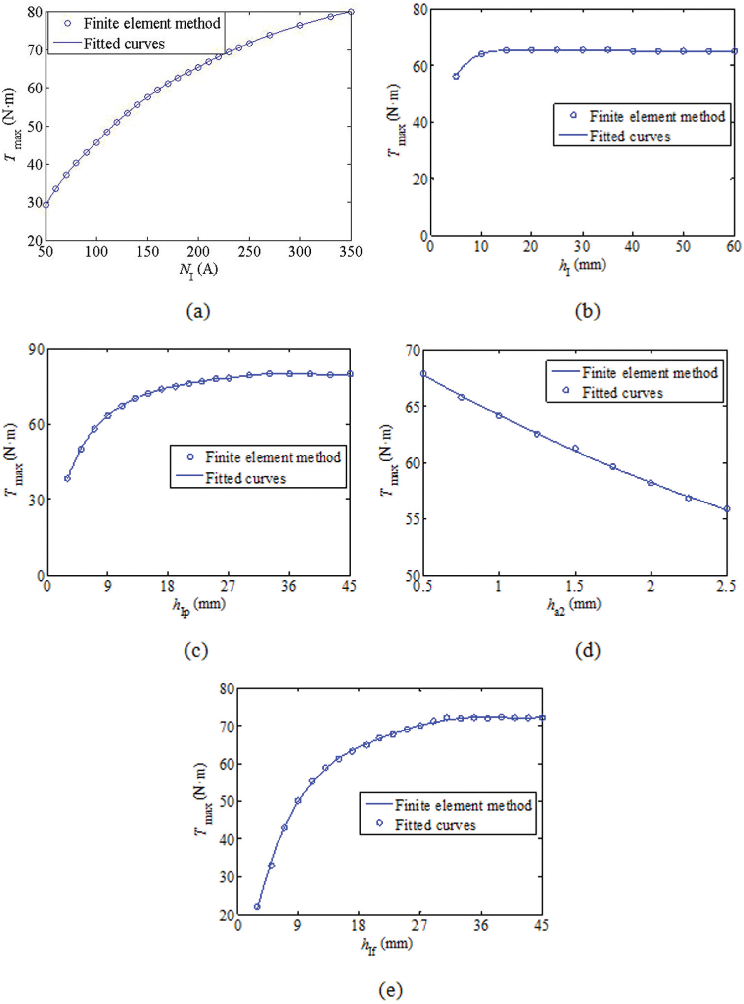
Torque curves of the first drive with an increase in the design parameters: (a) torque change with NI, (b) torque change with hI, (c) torque change with hIp, (d) torque change with ha2, and (e) torque change with hIf.

Torque curves of the EIMG with an increase in the design parameters: (a) torque change with Br, (b) torque change with ho, (c) torque change with hof, (d) torque change with ha4, and (e) torque change with hop.
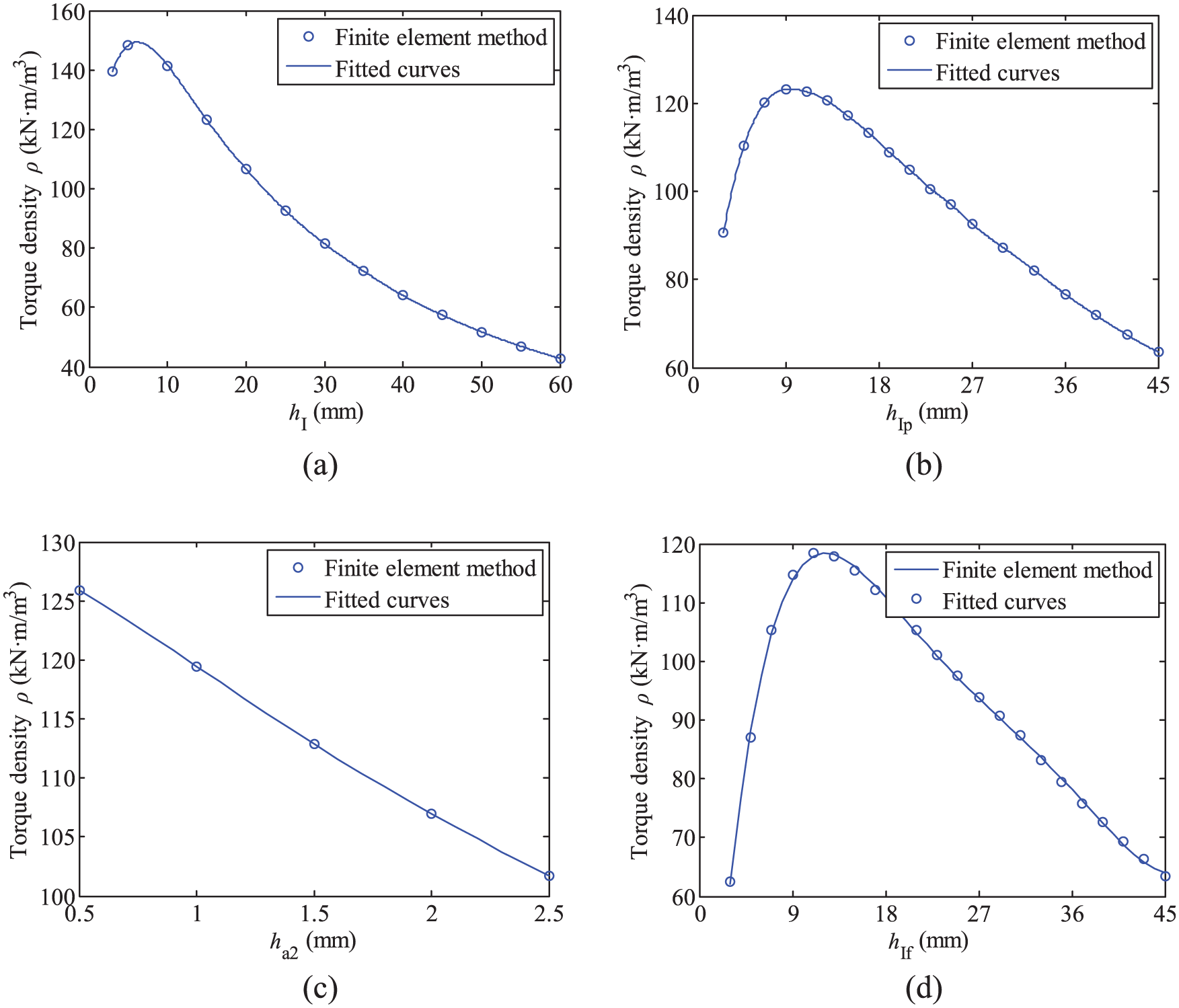
Torque densities of the first drive with an increase in the design parameters: (a) torque densities with hI, (b) torque densities with hIp, (c) torque densities with ha2, and (d) torque densities with hIf.
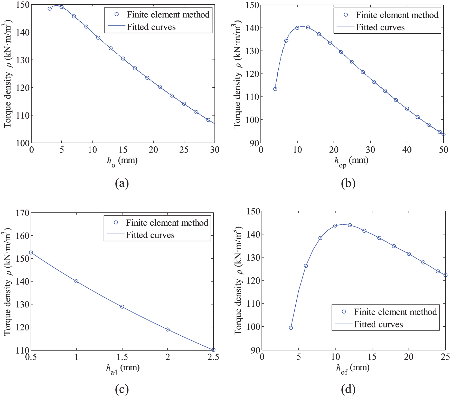
Torque densities of the EIMG with the increase in the design parameters: (a) torque densities with ho, (b) torque densities with hop, (c) torque densities with ha4, and (d) torque densities with hof.
Figure 10(a) indicates that with an increase in current magnitude NI, the maximum torque on the inner rotor increases. The magnetostatic energy in the inner stator and the intensity of the magnetic field increases when NI increases. When the thickness and the remanence of the PMs on the inner surface of the inner rotor are invariable, the maximum torque on the inner rotor increases rapidly. Meanwhile, the iron core volume of the inner stator and the first drive increases slowly. As such, the torque density of the first drive increases gradually.
Similarly, the maximum torque on the outer FP increases linearly with an increase in remanence Br because magnetostatic energy and magnetic field intensity increase with increasing Br. Meanwhile, EIMG volume remains unchanged; therefore, the corresponding torque density increases proportionally. The curve is not presented in this article. High-performance PMs can improve the transmission capacity and the utilization rate of the PMs.
Figures 10(b) and 11(b) illustrate that the maximum torques on the inner rotor and outer FP increase gradually to a constant with an increase in the thicknesses of the back irons of the inner rotor hI and the outer stator ho, respectively. Magnetic saturation occurs when the back iron is too thin; the thicker the back iron, the more permeable it is. Then, the output torques and magnetic resistances increase gradually. The invariable magnetostatic energy in the inner rotor and the outer stator causes the output torques to increase gradually to certain values. Figures 12(a) and 13(a) show that torque density first increases and then decreases rapidly with the thickening of the back irons because the volume of the first drive and EIMG increase quickly, respectively.
Figures 10(c) and 11(c) indicate that the output torques on the inner rotor and outer FP increase gradually to certain values when the thicknesses of PMs on the inner surface of the inner rotor and on the outer stator (hIp and hop) increase, respectively. When the PMs thin out and their thicknesses increase gradually, the magnetic flux density of the air-gaps beside the PMs increases along with the maximum output torques. The coupling areas of the inner surfaces of the PMs are constant; therefore, magnetostatic energy and magnetic resistance reach equilibrium when the PMs thicken to a certain extent. In addition, the output torques tend to be constant. As shown in Figures 12(b) and 13(b), the torque density of the first drive and EIMG first increase and then decrease rapidly because the maximum torques are constant, and the volumes increase invariably.
Figures 10(d) and 11(d) suggest that the maximum torques on the inner rotor and outer FP decrease when air-gap thickness hai (i = 1, 2, 3, 4) increases. Because of the low air permeability, the magnetic resistance among components and the magnetic potential loss increase with the increasing air-gap thicknesses. Subsequently, the output torques decrease gradually. To increase torque, the air-gaps must thin out. As a result, the volumes of the first drive and EIMG change only slightly. In addition, the torque densities presented in Figures 12(c) and 13(c) decrease when air-gap thicknesses increase.
Figures 10(d) and 11(d) suggest that the maximum torques on the inner rotor and outer FP increase rapidly and then gradually to certain values with an increase in the thicknesses of the inner and outer FPs (hIf and hof), respectively. When hIf and hof are small, magnetic field coupling with equal magnetic poles cannot occur in the air-gaps beside FPs. Thus, the field modulation results are unsatisfactory. When hIf and hof increase, the field modulation effects are strengthened. In the process, regular magnetic fields with equal magnetic poles form gradually. Then, the torques and magnetic resistances increase rapidly. When hIf and hof increase to certain values, the field modulation reaches saturation. At this point, the torque increases that are caused by the expansion of the outer surfaces of the inner and outer FPs reach equilibrium with an increase in magnetic resistances. Consequently, the output torques increase to certain values. The volumes of the first drive and EIMG increase constantly with hIf and hof; thus, the corresponding torque densities first increase and then decrease, respectively. These results are exhibited in Figures 12(d) and 13(d).
Although these design parameters influence one another and significantly affect the maximum torque of the EIMG, the ideal scopes of design parameters can be found and are shown in Table 2.
Ideal EIMG design parameters.

EIMG: electromechanical integrated magnetic gear; PM: permanent magnet; FP: ferromagnetic pole.
Except the maximum torque, the design parameters have great influences on the transmission efficiency. These will be further discussed in later research.
Conclusion
EIMG has the advantages of a high speed ratio and can generate a high output torque at low speed. Multiple harmonics can be observed in the magnetic fields of all the air-gaps; however, only a single harmonic component can be detected in the electromagnetic torques on all the components. The static torques on all the components change sinusoidally with the relative positions of components. The maximum torque and the torque density of EIMG are evidently affected by the design parameters, particularly the magnitude of the current, the remanence of the PMs, the thickness of the FPs, the thickness of the air-gaps, and the thickness of the PMs. Parameter optimization is important to reduce manufacturing cost and improve EIMG transmission capacity.
Footnotes
Academic Editor: António Mendes Lopes
Declaration of conflicting interests
The author(s) declared no potential conflicts of interest with respect to the research, authorship, and/or publication of this article.
Funding
The author(s) disclosed receipt of the following financial support for the research, authorship, and/or publication of this article: This research was supported by the Natural Science Foundation of China (no. 51205341).