
Abstract
This article presents research of sprinkled heat exchangers. This type of research has become rather topical in relation to sea water desalination. This process uses sprinkling of exchangers which rapidly separates vapour phase from a liquid phase. Applications help better utilize low-potential heat which is commonly wasted in utility systems. Low-potential heat may increase utilization of primary materials. Our ambition is to analyse and describe the whole sprinkled exchanger. Two heat exchangers were tested with a similar tube pitch: heat exchanger no. 1 had a four-tube bundle and heat exchanger no. 2 had eight-tube bundle. Efforts were made to maintain similar physical characteristics. They were tested at two flow rates (ca 0.07 and 0.11 kg s−1 m−1) and progress of boiling on the bundle was observed. Initial pressure was ca 10 kPa (abs) at which no liquid was boiling at any part of the exchanger; the pressure was then lowered. Other input parameters were roughly similar for both flow rates. Temperature of heating water was ca 50°C at a constant flow rate of ca 7.2 L min−1. Results of our experiments provide optimum parameters for the given conditions for both tube bundles.
Introduction
A sprinkled tube bundle is frequently used in technology processes where increase or decrease in a liquid temperature in a very low-pressure environment is required. A very thin liquid film covering a tube bundle contributes to a minimal influence of hydrostatic pressure on the process. Heat transfer between a tube wall and a cooling liquid at absolute pressures of hundreds of Pascals can be realized in case of decreasing pressure in the tube bundle surroundings. In such conditions, the heating of the liquid film is often connected with a phase transition which significantly increases the heat transfer at a sprinkled bundle.
A typical application that utilizes a sprinkled tube bundle operating in a low-pressure environment is the process of sea water desalination. Within this process, a tube bundle is sprinkled by a cool sea water of a low flow rate, creating thus a thin liquid film heated by the tube wall. As the water temperature is increased, a phase transition occurs and vapour is released from a liquid film. Research of heat transfer in this specific application was carried out by Yang and Shen, 1 Sharma and Mitra, 2 Crepinsek et al. 3 or Bobinska et al. 4 The principle of this type of distillation is based on this very low operational pressure of the water being desalinated that enables the process of desalination to be realized at temperatures of tens of degrees centigrade. Such operational conditions facilitate the use of low-potential waste heat from other processes.
Another significant application using a sprinkled tube bundle is the absorption cooling technology. The basic operation substance pair in absorption units is water combined with absorbent, usually lithium bromide. Within this application, water functions as a coolant. Absorption cooling units utilize sprinkled tube bundles to make water boil in an evaporator at a very low pressure, which is a precondition for achieving a low boiling temperature. Within this application, water is sprinkled onto a tube bundle with cooled substance flowing inside. By a sharp decrease in pressure in the bundle surroundings, water starts to boil at the surface of sprinkled tubes and heat is derived from the cooled substance. In ideal conditions, water boils at the whole surface of the exchanger, but in practice it must be considered that in original spots of contact between water and the exchanger wall the water will not boil at the tubes’ surface but the cooling liquid will merely be heated-up. And problems of development to boiling sprinkled tube bundle are devoted to this article. Sprinkled tube bundles are not a new technology; however, they have been researched and designed in experiments when commonly only one heated tube was scrutinized under laboratory conditions.5–8 This article includes information of analysis and describes the whole sprinkled exchanger.
A liquid flowing through a horizontal tube bundle forms three basic sprinkle modes visible in Figure 1.
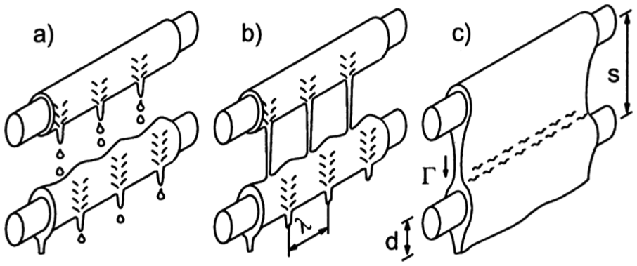
Sprinkle modes: 9 (a) at a low flow rate, the liquid drips from one tube to another in the so-called droplet mode; (b) with an increasing flow rate, droplets merge and form columns in the jet mode; and (c) with a further flow rate increase, the columns merge and first form sheets which are with an additional flow rate increase merged together until they fill in the whole gap between the tubes (sheet or membrane mode). 9
Measurement apparatus
For the purposes of examination of the heat transfer at sprinkled tube bundles, a test apparatus has been constructed; see the measurement diagram in Figure 2. A tube bundle at which a heat transfer from heated water flowing inside the tubes into a falling film liquid is studied is placed in a vessel where low pressure is created by an exhauster through an ejector.

Measurement diagram.
The test apparatus chamber is a cylindrical vessel of the length 1.2 m with three apertures in which the tube bundle of the examined length 940.0 mm is inserted. The tube bundle is installed in two fitting metal sheets which define the sprinkled area. The bundle consists of eight copper tubes of the diameter 12.0 mm situated horizontally one above another, with a distribution tube above them with apertures of the diameter from 1.0 to 9.2 mm. The bundle can be operated using only the first four or six tubes.
Two closed loops are connected to the chamber: a heating one and a sprinkling one. The heating liquid flowing inside the tubes is intended for overpressure up to 1.0 MPa. The second loop contains flowing falling film liquid. There is a pump, a regulation valve, a flow meter and plate heat exchangers attached to both loops. The plate heat exchanger at the heating loop is connected to a gas boiler which supplies heat to the heating liquid. The sprinkling loop uses two plate heat exchangers. In the first one, the falling film liquid is cooled by cold drinkable water from water mains and the falling film liquid is cooled in the second exchanger by drinkable water cooled in a cooler which regulates the temperature up to 1.0°C. In order to enable visual control, the heating loop also includes a manometer and a thermometer. The thermal status in individual loops is measured by wrapped unearthed T-type thermocouples on the agents’ input and output from the vessel. All thermocouples have been calibrated in the CL1000 Series calibration furnace which maintains a given temperature with the accuracy of ±0.15°C. None of the thermocouples has exceeded the error ±0.5°C within the studied range from 28°C to 75°C. That is why the total error at temperature measurement is set uniformly for all thermocouples along the whole studied range ±0.65°C.
There are three vacuum gauges measuring the low pressure. The first vacuum gauge is designed for visual control and it is a mercury meter, the second one is a digital vacuum gauge Baumer TED6 and enables measuring within the whole desired low-pressure range, but it is less accurate with lower pressure values. To allow a precise measuring of the low spectrum, a third digital vacuum gauge of the range 2.0 kPa–0 Pa is used. The accuracy of a vacuum gauge, the results of which have been used for the assessment, is 0.5% from the measured range, that is, ±0.5 kPa.
Electromagnetic flow meters Flomag 3000 attached to both loops measure the flow rate. The flow meters’ range is 0.0078–0.9424 L s−1, where the accuracy is 0.5% from the measured range, that is, ±0.00467 L s−1. All examined quantities are either directly (thermocouples) or via transducers scanned by measuring cards DAQ 56.
Methodology of data assessment
The assessment of the measured data is based on the thermal balance between the operation liquid circulating inside the tubes and a sprinkling loop according to the law of conservation of energy. Heat transfer is realized by convection, conduction and radiation. In lower temperatures, the heat transferred by radiation is negligible; therefore, it is excluded from further calculations. The calculation of the studied heat transfer coefficient is based on Newton’s heat transfer law and Fourier’s heat conduction law that have been used to form the following relation
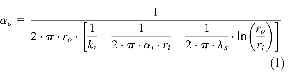
where αo (W m−2 K−1) is the heat transfer coefficient at the sprinkled tubes’ surface; αi (W m−2 K−1) is the heat transfer coefficient at the inner side of a tube set for a fully developed turbulent flow according to Jícha; 10 ro, ri (m) are outer and inner tube radii; λs (W m−1 K−1) is thermal conductivity; ks (W m−1 K−1) is heat admittance based on the above-mentioned laws governing heat transfer which is calculated from heat balance of the heating side of the loop, that is why the following must be valid

where
The above-mentioned calculation is valid only for heat transfer from water flowing inside the tubes into a falling film liquid which does not boil at the surface or where insignificant boiling may occasionally occur at the last tube. In case boiling occurs at a major part of the tube bundle, that is, the tube bundle is sprinkled by a saturated water or higher at a corresponding pressure in a chamber pV (Pa), two-phase flow should be considered. The amount of developed steam can be calculated according to the law of conservation of mass. That is, the sum of the mass flow rate of steam Mv (kg s−1) and the mass flow rate of the water flowing down after the exchanger Mf (kg s−1) must equal the mass flow rate flowing from a distribution tube M1 (kg s−1). However, there are two unknown variables in this equation. That is why it is necessary to apply the law of conservation of energy as well. That is, the sum of the energy necessary to develop steam Qv (W) and the energy transferred to a falling film water Qf (W) must equal the energy supplied by the heating liquid QS (W). Then, the following is valid for the calculation of the amount of developed steam

under the condition that the temperature of the falling film water t1 (°C) in a distribution tube is maximum at the saturation boundary or slightly below it. In the mentioned equation, iIN (J kg−1) stands for the enthalpy of a developed steam cushion at the temperature tIN (°C), and i2 (J kg−1) stands for the enthalpy of a heated falling film water at the temperature t2 (°C), after the last tube.
The studied heat transfer coefficient can be determined on the basis of Newton’s law of heat transfer where the wall temperature is set as a mean temperature of the heating water and the temperature of the liquid flowing around it as a mean value of the temperature of a falling film water flowing out of the distribution tube and the temperature of a steam cushion
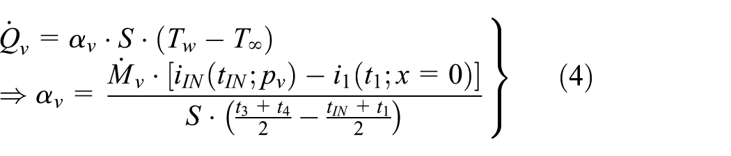
where S (m2) stands for a heat transfer region, that is, the surface of the tube bundle.
Experimental results
We are presenting here four of our experiments which were conducted on two tube bundles. The bundles each comprised four and eight tubes. We were interested in the progress of boiling on a sprinkled tube bundle with different flow rates of the sprinkling liquid. First, the average flow rate was 4.03 ± 0.02 L min−1 (average value for both bundles); second, the average flow rate was 6.03 ± 0.02 L min−1 (average value for both bundles). Mass flow rate of the falling film liquid related to the length of the sprinkled area (940 mm in our experiments) is a quantity more commonly defined for sprinkled tube bundles. Flow rate, designated as ‘Γ’, was 0.0704 ± 0.0004 kg s−1 m−1 for the first case and 0.1055 ± 0.0004 kg s−1 m−1 for the second case. Average temperature of the heating water entering bottom tube of the bundle was 50.2°C ± 0.3°C, and average flow rate of the heating water was 7.23 ± 0.01 L min−1.
Figure 3 presents part of the recording of main measured quantities over time (experiment 1: tube bundle comprising four tubes, flow rate: ca 4 L min−1). Flow rates of falling film water and heating water were set to required parameters. Initial temperature of falling film water was ca 20°C. External pressures of 4.0 kPa (abs) in the device were created using a vacuum and jet-pump. Steam forming in the device was pumped out throughout the whole experiment. Temperature of the falling film water was gradually increased, which means that considering the design of the closed sprinkling loop, the water was not cooled towards the end of the experiment.

Record of main measured quantities.
Figure 3 also shows derived quantities. This includes heat flow extracted from the heating liquid (Q_34) and heat flow absorbed from sprinkling water (Q_12), that is, water in liquid phase. Both heat flows are trending down, even when approximately constant flow rates of the liquids are observed, because thermal difference was decreased. Another quantity displayed in the figure is a heat transfer coefficient on the inside tube wall (alpha_i) and heat transfer coefficient on the tube surface (established using equation (1) for liquid phase). Despite the significant decrease in thermal difference, the coefficient is only slightly trending upwards. All four experiments are shown in the following figures. The horizontal axis is identical for all figures and represents current temperature of the sprinkling water leaving the distribution tube for the specific time minus saturation temperature assigned to the current pressure in the chamber for the same time.
Figure 4 shows a surface, identified by a linear approximation, where the liquid is boiling and the boiling proceeds from the very bottom tube upwards. At 100% of the surface, the liquid has at least a saturation temperature already in the distribution tube. If the surface with boiling is only slightly higher than zero, the temperature of the sprinkling liquid beyond the bundle is at a saturation point.

Comparison of surface areas with boiling.
In the figure, 50% surface corresponds to a saturation point reached between tubes 4 and 5 (eight-tube bundle) and tubes 2 and 3 (four-tube bundle). The figure clearly shows that the larger the surface for the heat flow, the sooner the liquid reaches saturation temperature.
Figure 5 displays coefficients of liquid phase (alpha_f – determined by equation (1)). Values for non-boiling water are displayed in the figure for pressure in the chamber of 10 kPa (abs) and more, which corresponds with temperatures of ca −28 and lower. Coefficients trended slightly upwards as the pressure was decreased and remained approximately at the same level for the given flow rate of the sprinkling liquid. The coefficient dropped when the boiling significantly affected the last tube. The decrease may be attributed mainly to the rising temperature of the falling film liquid in the distribution tube, and development of steam layer on the tube wall, which impedes heat transfer to the liquid phase. This is especially important for the bottom half of the bundle where the tube wall temperature is higher. When the boiling was occurring at 50%–60% of the surface, the decrease in the coefficient stopped and then it became stabilized.

Comparison of heat transfer coefficients of liquid phases.
Water starts to boil at the bottom section of the exchanger at pressures of ca 6.5 kPa and less. As the surface area with boiling water gets larger, there is a rapid drop in coefficient of the liquid phase. However, the coefficient remains at the same level despite an increase in sprinkling water temperature. Medium value of heat transfer coefficient of the liquid phase in case of non-boiling liquid is ca 10% higher for 6 L min−1 compared to 4 L min−1. In case of a boiling liquid, the coefficient is almost 20% higher (for four and eight tubes).
On the other hand, the course is relatively stable for coefficient of vapour phase (alpha_v – determined by equation (4)), as displayed in Figure 6. Coefficient in both cases will settle at ca 950 W m−2 K−1 at −2.0°C (four tubes) or at ca 787 W m−2 K−1 (eight tubes). The variance for all four cases was 950 W m−2 K−1 on average.
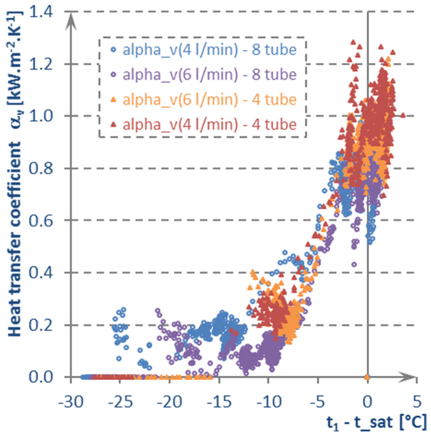
Comparison of heat transfer coefficients during vapour phase.
Lorenz and Yung 5 developed a mathematical model for a boiling liquid which circumflows one tube. This model was further expanded by Rohsenow, 6 Chien and Cheng 7 and Parken et al. 8 Mathematical model for a total heat transfer coefficient of the tube wall stems from a sum of partial coefficients of particular phases, which include phases (1) close to a boiling point, (2) expanding area and (3) fully expanded area. Second and third phases are moderated by a size of the area where the processes occur. By analogy, coefficients of liquid phase and vapour phase were added. Adding coefficients of the liquid phase and vapour phase (boiling occurs on the whole bundle surface), the sum is slightly higher (even in hundreds of W m−2 K−1) compared to the coefficient acquired by calculating only the heating of the liquid (no boiling).
Steam dryness is displayed in Figure 7. The values for steam dryness were determined using the amount of produced steam. The figure clearly shows increase in steam production during boiling; maximum was reached at ca −3.0 to −0.8°C below the boiling point of the sprinkling liquid; as the boiling progressed, steam production was lowered. The lower the flow rate, the higher share of steam was produced. But the quantity of produced steam had a similar trend as coefficient of the vapour phase. This means it reached the maximum and did not rise any further after the temperature of the sprinkling liquid flowing from the distribution tube was increased; the value for all four cases ranged around 0.5 g s−1, with ca 20% variance.

Comparison of produced steam dryness.
Figure 8 shows comparison of final total heat transfer coefficients (alpha_t); average value and its standard deviation represent each experiment. Both these values were determined once the process was stabilized. Coefficient is displayed in dependence to Reynolds number. Our results were compared to two studies which had presented criterion function. These equations operate with Nusselt’s criterion expressed as a function of Reynold’s and Prandtl’s number, or of a heat flux. We set measured state variables in the equation. Other physical quantities necessary for the calculations were determined using the measured values. The study by Chun and Seban 11 is the first study compared; it describes experiments with an exchanger comprising one tube which were later refined, for example, by Cooper 12 and Rohsenow. 6 Points in the chart are marked as ‘Study A’. The study no. 2 is by Chien and Cheng 7 which uses the results of heat transfer coefficient at a vertical wall. This is marked as ‘Study B’.

Comparison of results with other studies.
Conclusion
This article presents results of our research in sprinkled exchangers. We compared boiling on a sprinkled tube bundle which comprised four or eight horizontally stacked tubes. Two flow rates of sprinkling liquid on both tube bundles were tested and compared: ca 0.07 and 0.11 kg s−1 m−1. Droplet mode has been reached in both tested flow rates. Other parameters were roughly similar. Initial pressure of the liquid was ca 10 kPa (abs); no boiling occurred at this pressure and the pressure was then slowly lowered. Temperature of the sprinkling water in a distribution tube was ca 20°C at the beginning of the experiments. The temperature was raised after the minimum pressure was attained; this initiated boiling on the whole surface of the exchanger. Temperature of the heating water entering the exchanger was maintained at ca 50°C at a constant flow rate of ca 7.2 L min−1.
Charts show a rapid drop of heat transfer coefficient on the surface of the tube bundle as the boiling progressed. After that, the coefficient is stabilized on the same level although the temperature of the sprinkling water rises. The coefficient for the flow rate of 0.11 kg s−1 m−1 is almost 20% higher compared to the flow rate of 0.07 kg s−1 m−1. On the other hand, course of the coefficient of the vapour phase for both flow rates is roughly similar as well as amount of produced vapour. Considering the maxima, optimum temperature of the sprinkling water leaving the distribution tube may be identified. For heat transfer coefficient, the temperature is ca −2°C below saturation temperature (and more); for amount of produced vapour, the temperature ranges from −3°C to −0.8°C below saturation temperature. Therefore, optimum temperature of the sprinkling water ranges from −2°C to 0.8°C below saturation temperature. In terms of the sprinkled tube bundle size, boiling occurred earlier at the bundle with eight tubes but the heat transfer coefficient was lower by ca 17%. In terms of the total heat transfer coefficient on the surface of the sprinkled tubes, the bundle with four tubes is better since the coefficient of the liquid phase is dominant.
Footnotes
Academic Editor: Chin-Lung Chen
Declaration of conflicting interests
The author(s) declared no potential conflicts of interest with respect to the research, authorship, and/or publication of this article.
Funding
The author(s) disclosed receipt of the following financial support for the research, authorship, and/or publication of this article: This work is an output of research and scientific activities of NETME CENTRE PLUS (LO1202) by financial means from the Ministry of Education, Youth and Sports under the “National Sustainability Programme I”.