
Abstract
Axial-centrifugal combined compressors are commonly used, and the stresses of their impeller are important and influenced by temperature and pressure. The effects of temperature and pressure on the stresses of the impeller with different inlet conditions are investigated. Conjugate heat transfer analysis and three-dimensional structural finite element analysis are used to get the stresses of the impeller. The effects of temperature and pressure are obtained by comparing the equivalent (Von-Mises) stresses between cases taking and not taking them into account. From the result, the temperature effect is surprisingly large for low inlet temperature, reaching 57% of the total equivalent stress, and should be carefully considered. The effect strongly relates with the inlet conditions and the disk thermal boundary conditions. Thus, the later can’t be treated as adiabatic as usual. For certain inlet conditions, the stress of the impeller can be improved by adjusting the disk thermal boundary conditions. In addition, the temperature mainly affects the stress on the disk and the root of the blade. The pressure effect is small for low inlet temperature and can be sufficiently large for high inlet temperature. Furthermore, the pressure mainly influences the stress on the blade part and can reduce the stresses at the inducer of a negative-lean impeller.
Introduction
Axial-centrifugal combined compressors are commonly used in small aeroengines, 1 of which the stresses of the impeller are very important for the reliability. As rotating components, the disk of the impeller suffers from large centrifugal load and thermal load 2 and can be torn apart by the tensile stress at the circumferential direction when the rotating speed is high 3 or under large temperature gradient. The blade will suffer high-cycle fatigue because of the unstable aerodynamic load, 4 and easier to break up when the stress is high. 5 Besides, the weight of the machine tends to decrease for better economy and performance.
For those reasons, it is important to predict the stress of the impeller accurately. Many efforts have been put into the stress analysis of impellers. In the early days, analytical methods were used to investigate the approximate stresses of the impeller under only centrifugal load 6 and are now only used during conception design. 7 Taking advantage of development of the computer-aided finite element analysis (FEA) method, the stresses of the impeller under only centrifugal load can be predicted accurately. 8
However, with increasing the pressure ratio of the compressor, the effects of temperature and pressure on the stresses of impellers are more and more evident. Mukherjee and Baker 9 used heat transfer coefficient derived from experiments to analyze the stresses of a turbocharger impeller at pressure ratio of 4:1 and found that thermal load had a significant contribution to total stresses. Zheng et al. 10 used a solid–fluid coupled method to analyze the stresses of a turbocharger impeller under several pressure ratios and found that aerodynamic load had little effects on total stress and the effects of thermal load must be considered at high pressure ratio.
For axial-centrifugal combined compressor, it is usually a combination of one centrifugal compressor and a multistage axial compressor, as shown in Figure 1. With different configuration of axial compressors ahead, the inlet conditions (e.g. pressure and temperature) of the centrifugal impeller also vary considerably. The stress level of the impeller is supposed to be affected by this varied inlet conditions, even when the operating point (e.g. total pressure ratio and mass flow rate) of the centrifugal compressor is kept the same. However, this effect is not quite clear yet.

Axial-centrifugal combined compressor.
To investigate the effects of inlet conditions on the stresses of impeller, conjugate heat transfer analysis is adopted to get the temperature and pressure of the impeller and a fluid–solid coupling method is used subsequently to get the equivalent (Von-Mises) stress. The influence of temperature and pressure is obtained by comparing the equivalent (Von-Mises) stress between cases taking and not taking the certain load into account.
Methodology
Study object
In this article, an impeller with 15 main blades and 15 splitters is studied, as shown in Figure 2. The outlet diameter of the impeller is 120 mm.
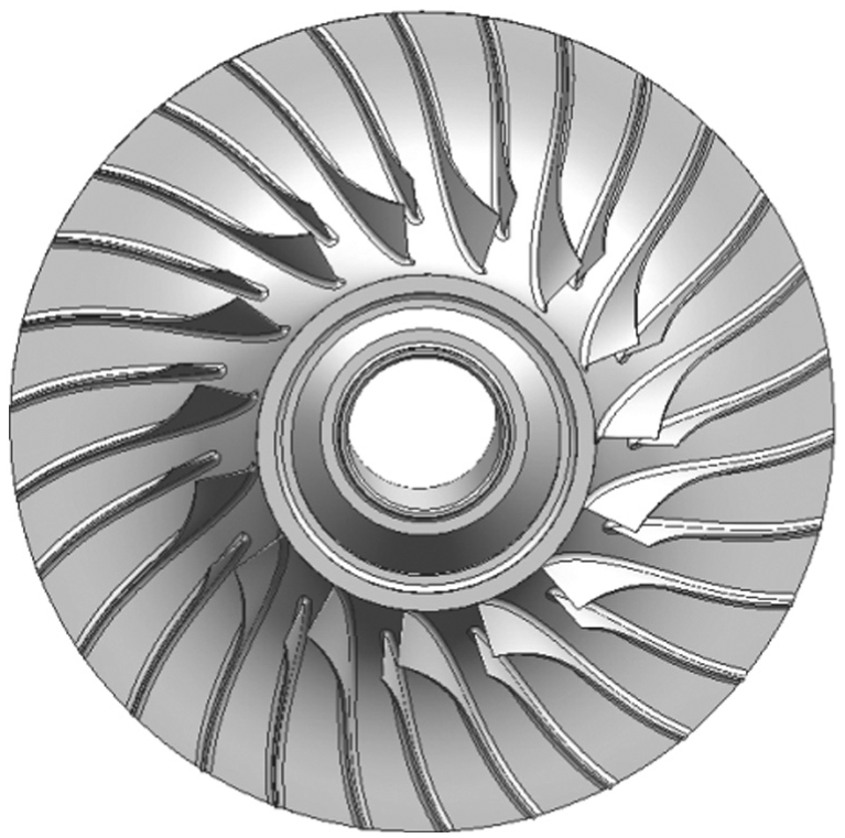
Impellor of an axial-centrifugal combined compressor.
The impeller is used for all the cases. Different axial compressors with an 85% isotropic efficiency are assumed to be ahead the impeller for different cases. The pressure ratio and the inlet Mach number of the impeller for the different cases are set same so that the stress can be compared at the same working point of its corrected map, as shown by dot in Figure 3.

Compared point on the corrected map of the impeller.
The material of this impeller is GH4169 and its properties at different temperatures are shown in Table 1, where λ is the thermal conductivity, C is the specific heat capacity, α is the thermal expansion coefficient, ρ is the density, and E is the modulus of elasticity.
Properties of GH4169.

Conjugate convective heat transfer analysis
Conjugate convective heat transfer analysis was conducted by CFX to get the body temperature and surface pressure of the impeller. 11 Because of the periodicity of the impeller, only one impeller passage including a main blade and a splitter is calculated. The meshes of the impeller are shown in Figure 4, including 344,080 nodes for the fluid domain and 328,816 nodes for the solid domain, according to the grid dependence made before by Zheng and Lan. 12

Meshes for conjugate convective heat transfer analysis.
For the simulation of the fluid domain, the control equations are three-dimensional steady compressible Reynolds-averaged Navier–Stokes equations in conservative formulation. The equations are as follows


where
The inlet total temperatures and total pressures of the impeller are deduced from the pressure ratio and isotropic efficiency of the axial compressors. The outlet static pressures are set to keep the pressure ratio of the impeller constant for different axial compressors. And the rotating speeds are corrected by equation (4)

where T0 is 288.15 K, Tt is the inlet total Temperature of impeller, n is the rotating speed when the inlet total temperature is T0, and nc is the rotating speed when the inlet total temperature is Tt. Thus, the impeller works at the same corrected rotating speed for different cases.
The velocity direction is set normal to the inlet boundary. Non-slip and impermeability conditions are imposed on the solid walls. Except for the interfaces, other surfaces of the fluid domain are set adiabatic. In the circumferential direction, a periodical boundary condition is imposed.
For heat transfer, the interfaces between the solid domain and the fluid domains are taken as the inner boundary. The fluid part and solid part are coupled by conservative heat flux at the fluid–solid interfaces. The heat transfer coefficient is determined by the iterative calculation between fluid and solid domain. Heat transfer through the solid is governed by the conservation of energy equation, which is equation (5)

where T is the temperature.
The thermal boundary conditions of the solid part are set by surface temperatures deduced from experiments and are same for different cases, as shown in Figure 5. Other surfaces are set to be adiabatic.

Thermal conditions of the solid part of the impeller.
Taking advantage of conjugate heat transfer analysis, the temperature of the fluid field and solid domain can be solved accurately. 13 The temperature of the solid domain and pressure at the interfaces are then imported to subsequent structural analysis as boundary conditions.
Structural analysis
FEA is used in the structural analysis by ANSYS to get the stress of the centrifugal compressor impeller. 14 As cases are linear elastic and isotropic three-dimensional solid with thermal load, the control equations are as follows


where
The body temperature of the impeller and the pressure at the interfaces are loaded from the results of the conjugate heat transfer analysis. A corrected rotating speed is imposed to the impeller. The forward and backward surfaces of the disk are constraint in the circumferential and axial directions to simulate the interaction with structures ahead and behind it, 15 as shown in Figure 5. Cyclic periodical boundary conditions are imposed in the circumferential direction.
Result and analysis
Total stress
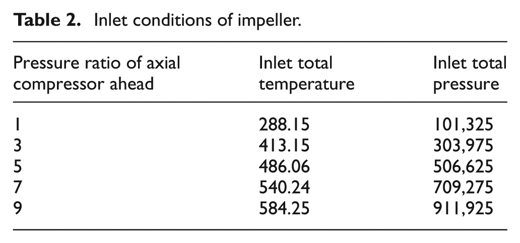
The inlet conditions of the impeller were calculated by assuming a pressure ratio and isentropic efficiency of the upstream axial compressors. In this work, the axial compressors with pressure ratio 1, 3, 5, 7, and 9 and an 85% isotropic efficiency are assumed, and the flow distortion induced by the upstream rotor was neglected.
The inlet total pressure and total temperature of the impeller can be deduced by equations (8) and (9)


where p0 is 101,325 Pa, pt is the inlet total pressure of impeller, π is the pressure ratio of the axial compressor ahead, and η is the isentropic efficiency. Table 2 gives the inlet conditions of impeller for different cases. Figure 6 shows the equivalent (Von-Mises) stress distributions of the impeller for different inlet conditions.
Inlet conditions of impeller.

Total stress distribution of impeller of different cases.
The impeller suffers large stress at the root of the main blade and splitter for low inlet temperatures and at the center of the disk for high inlet temperatures, which are threatened to be torn apart. Working with the high frequency unstable aerodynamic load, the blades are easy to break up because of fatigue. For the reason, the stresses at five featured points are monitored for further analysis. They are the maximum stress point at the root of the main blade (M_Root), the maximum stress point at the root of the splitter (S_Root), the maximum stress point on the surface of the main blade (M_Surface), the maximum stress point on the surface of the splitter (S_Surface), and the maximum stress point at the center of the disk (D_Center), as shown by dots in Figure 6.
The total equivalent stresses of the monitored points in Figure 6 are shown in Figure 7, varying with the inlet temperatures of the impeller for different cases. It can be seen that for low inlet temperature, the total equivalent stress at the root of the blades is the largest, while for high inlet temperature the total equivalent stress at the center of the disk becomes the largest of the impeller. At certain temperature range, as the increase in the inlet temperature, the total equivalent stress at the blade root blades decreases, especially for the main blade, while the equivalent stress at the center of the disk increases. As a result, there are inlet conditions which make the equivalent stress at the root of the blades equal to the equivalent stress at the center of the disk, thus making the maximum equivalent stress of the impeller the smallest for the thermal condition of the impeller.
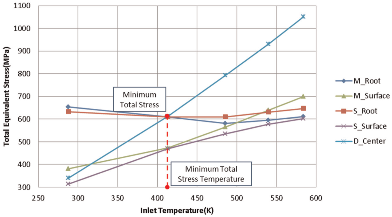
Total equivalent stresses at the monitored points in Figure 6.
Effect of temperature on impeller stress
To figure out the effects of the temperature on the impeller stress, the thermal stress is defined to be the difference of the total equivalent stresses (Von Mises) of the impeller with real body temperature and that with a uniform temperature (22°C). According to the definition, a positive thermal stress means that the thermal load increases the total equivalent stress of the impeller while a negative one means the thermal load decreases the total equivalent stress.
The ratios of the thermal stresses to the total stresses at the monitored points for different inlet conditions are presented in Figure 8. As it shows, the thermal stress can be 57% of the total equivalent stress when the inlet temperature is 288.15 K, which means that the temperature has to be considered when analyzing the stress of the impeller. It is also obvious that for low inlet temperature, the thermal stresses are large and positive for points at the root of the blades (M&S_Root) but negative for points at the center of the disk (D_Center). With the increase in the inlet temperature, the thermal stresses at both places decrease. The thermal stresses on surface of the blades are relatively small.
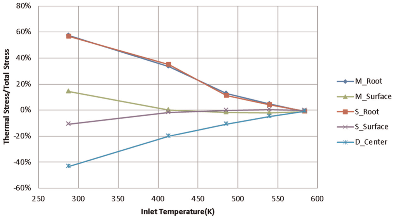
Thermal stresses of the monitored points.
For explanation, two annulus rings with non-uniform temperature distribution in the radical and axial direction are separately illustrated in Figure 9 to describe the mechanism of how the temperature distribution influences the stress of the impeller.
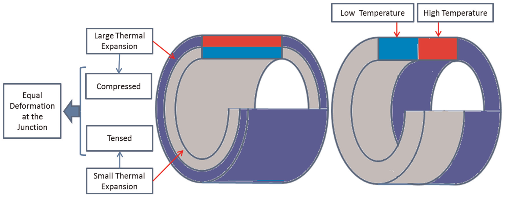
Annulus rings with non-uniform radical and axial temperature distribution.
With non-uniform temperature distribution in the radial or axial direction, the thermal expansion in the circumferential direction will be different for areas in the meridian plane. For the high temperature area, the expansion will be larger, while for the low temperature area, smaller. However, as the areas are connected with each other, the deformation must be equal at the junction. Thus, the high temperature area will be compressed to make its expansion smaller while the low temperature area will be tensed to make its expansion larger. As a result, tensile stress in the circumferential direction is generated at low temperature area while compression stress generated at high temperature area.
The disk of the impeller can be considered as a special annular ring with non-uniform temperature distribution in the radical and axial directions. Thus, tensile stress in the circumferential direction is generated at low temperature areas while compression stress at high temperature areas in the meridian plane. For stress caused by the centrifugal load tends to be tensile, the tensile stress generated by non-uniform temperature will enlarge the total stress and cause a positive thermal stress while the compression one will reduce it and causes a negative thermal stress.
Figure 10 shows the calculated temperature distribution of the impeller. The calculated temperature distribution of the impeller is decided by the surface temperatures set at the inner disk, which is constant and the temperature of the fluid, which is decided by the inlet condition of the impeller for a constant working state. For low inlet temperature, the surface temperatures at the inner disk are much higher than the fluid, which leads to the temperature at the outer disk is much lower than that at the inner disk. As a result, the stress at the outer disk, where the M&S_Root points located, is enlarged and the thermal stress is positive while the stress at the inner disk, where the D_Center points located, get reduced and the thermal stress becomes negative.
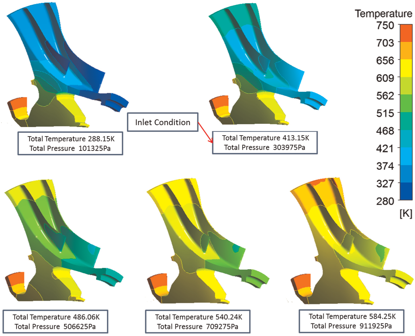
Temperature distribution of the impeller.
With the increase of the inlet temperature, the temperature of the fluid increases, which makes the temperature at the outer disk higher. While the surface temperatures at the inner disk are constant, the temperature distribution of the impeller becomes more uniform. Thus, the thermal stress decreases as shown in Figure 11.

Thermal stress distribution of the impeller.
As the thermal stress of the impeller relates with its temperature distribution which is decided by the fluid temperature and the thermal boundary conditions of the impeller, the thermal boundary conditions of the disk are very important and cannot be treated as adiabatic. For its influence on the stress of the impeller, the thermal boundary condition of the disk can be used to improve the stress of the impeller by controlling the temperature distribution of the impeller. In addition, the temperature mainly affects the stress on the disk and the root of the blade. As the stress of the impeller has much to do with the temperature of the disk, it also reminds that the cooling and the inlet condition of the impeller should coordinate with each other to get the lowest stress of the impeller.
Effect of pressure on impeller stress
As with the thermal stress, to figure out the effect of the pressure on the stress of the impeller, the aerodynamic stress is defined as the difference of the equivalent stress (Von Mises) with the aerodynamic load to that conducted in the vacuum. Similarly, a positive aerodynamic stress increases the total equivalent stress of the impeller while a negative one decreases the total equivalent stress.
Figure 12 shows the ratios of the aerodynamic stresses to the total stress for monitored points at Figure 6 for different inlet conditions. It can be seen that the aerodynamic stress at the center of the disk is nearly zero for all the inlet conditions. For low inlet temperature, the aerodynamic stresses are small. However, the aerodynamic stresses increase almost linearly with the inlet temperature for points except that at the center of the disk and can reach 18% of the total equivalent stress, thus cannot be ignored in the stress analysis of the impeller. The aerodynamic stress is positive at the root of the blades (M&S_root) and negative on the surface of the blades (M&S_Surface), which means the pressure enlarges the stress at the root of the blade while reduces it on the surface.
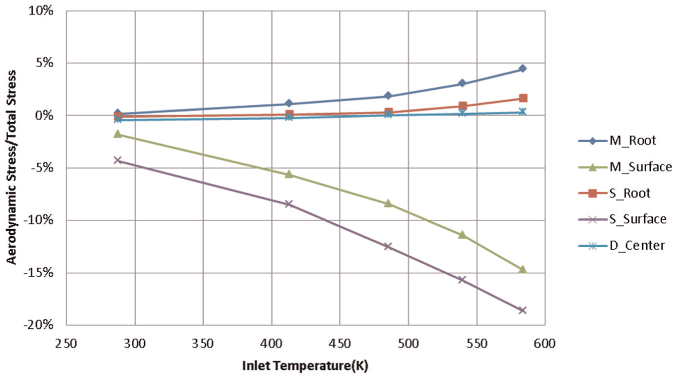
Aerodynamic stresses for monitored points.
To better understand the effect of the pressure, Figure 13 gives the distribution of the aerodynamic stress with different inlet conditions. It is noted that the distributions of the aerodynamic stress are similar and the aerodynamic stresses are positive at the rearward of the blades and negative at the front part of the blades and at the back of the disk. That means the pressure reduces the stress at the front part of the blades and at the back of the disk while enlarges it at the rearward of the blades.

Aerodynamic stress of some monitored point.
That is because the turning of the fluid in different streamsurfaces causes different counterforce to the impeller according to the conversation of the momentum. In blade-to-blade streamsurface, as the fluid turns along the blade, the counterforce tends to push the blade from the pressure side to the suction side. In meridional steamsurface, as the fluid turns upward at the rearward of the passage, the counterforce of the fluid tends to push the outer part of the impeller backward.
As the front part of the researched impeller blades lean to the suction side, the centrifugal force tends to pull the blades from the suction side to the pressure side. The centrifugal force effect is opposite with that of the counterforce in blade-to-blade streamsurface. Thus the stress is reduced. However, if the blades do not lean to the suctions side enough, the effect of the pressure will be different.
In the cases for the rearward of the blades and the back of the disk, the counterforce in meridional streamsurface plays an important role. As shown in Figure 14, as the outer part of the impeller is pushed backward, a tensile stress will be generated at the front side of the impeller and a compression stress at the back side of the impeller. As there is a predominant tensile stress caused by the centrifugal load, the stress at the front side is enlarged while the stress at the back side is reduced.

Radical normal stress of the impeller under only aerodynamic load.
Conclusion and remarks
In this article, the effects of temperature and pressure on the stress of the impeller working at the same state in different inlet conditions of temperature and pressure were studied. Conjugate heat transfer analysis was used to obtain the temperature and pressure of the impeller and the fluid which were then applied as boundary conditions in the three-dimensional structural FEA to obtain the stress of the impeller. Finally, the effects of temperature and pressure on the stress of the impeller were obtained by comparing the equivalent (Von-Mises) stress between considering and not considering the thermal load or the aerodynamic load. Two main conclusions are as follows:
The temperature effect can reach 57% of the total equivalent stress when inlet temperature is 288.15 K, which suggests that the temperature effect should be carefully considered in the stress analysis of the impeller. The effect of the temperature strongly relates with the inlet conditions of the impeller and the thermal boundary conditions of the disk, which cannot be treated as adiabatic. The stress of the impeller can be improved by controlling the thermal boundary conditions of the disk. In addition, the temperature mainly affects the stress on the disk and the root of the blade.
The pressure mainly influences the stress on the blade but hardly on the inner disk. For low inlet temperature, the pressure effect on the stress is small but increases almost linearly with the inlet temperature. The aerodynamic stress can reach 18% of the total equivalent stress when inlet temperature is up to 584.25 K, and must be considered in the stress analysis of the impeller. Furthermore, the fluid pressure can reduce the stress at the front of a negative-lean blade and the stress at the back of the disk.
Footnotes
Appendix 1
Academic Editor: Thirumalisai S Dhanasekaran
Declaration of conflicting interests
The author(s) declared no potential conflicts of interest with respect to the research, authorship, and/or publication of this article.
Funding
The author(s) disclosed receipt of the following financial support for the research, authorship, and/or publication of this article: This research was supported by the National Natural Science Foundation of China (Grant No. 51176087).