
Abstract
On the basis of design of experiment and numerical simulation, a reliable optimization method for blades of a mixed-flow pump is proposed with the maximum weighted average efficiency at multi-conditions as optimum objective. First, the performance of the model pump was measured and the test results were used to validate the simulation method. To improve the simulation accuracy, the check of the grid independence and the comparison of different turbulence models were done in detail. Then, the method of design of experiment for key geometrical parameters was used to obtain the optimization scheme. The maximum weighted average efficiency of pump at three operation conditions was chosen as optimum objective. The optimum solution was gotten and confirmed by the experiment. The results demonstrate that efficiency of the mixed-flow pump with optimized impeller increases by 3.9%, and the high-efficiency zone is increased from 0.021 to 0.040.
Introduction
Mixed-flow pump is a kind of vane pump with the high specific speed, which has been widely applied in the fields of agricultural irrigation, sewage disposal, and water treatment fields. Its structure and performance not only take the advantages of centrifugal pump and axial-flow pump but also make up the defects in inapplicability of centrifugal pump at low head and unstable flow of axial-flow pump at a small flow rate.1–3 With the needs of industrial development and the expansion of its applications, the performance requirement of mixed-flow pump is gradually increased such as the head and the efficiency, which means the mixed-flow pump only designed by one flow rate is difficult to meet the requirements.4,5 Meanwhile, the design method for mixed-flow pump is not fully developed, and there is an urgent need to improve the design method or put forward an optimization one.
Kim et al. 6 and Watanabe et al. 7 used numerical calculation and experimental design method to optimize the mixed-flow pump impellers, inlet blade angle of guide vane, and flow passage shape. Based on a weighted average surrogate model, Kim and Kim8,9 optimized a van diffuser in mixed-flow pump with higher specific speed to reduce the internal losses. And the efficiency of mixed-flow pump has been improved by 7.05% at the design flow coefficient. Li et al. 10 made an optimum design on impeller blade of mixed-flow pumps using computational fluid dynamics (CFD) method and improved their performance. Oh and colleagues11,12 carried out a conceptual design optimization of a mixed-flow pump with streamline analysis method. On the basis of the three-dimensional design platform of the mixed-flow pump impellers, Bing and colleagues13,14 developed an optimization design system by improving the genetic algorithm with single factor optimum method. The test results illustrated that the maximum efficiency of mixed-flow pump is 87.2%. Susanne and Rudolf 15 conducted the numerical optimization design for complex hydraulic machinery blades, and a number of design parameters and several optimization loops were calculated. Zhang and colleagues16,17 used mathematical optimization methods to optimize the geometrical parameters of flow passage components in mixed-flow pump with the objective function of improving efficiency of mixed-flow pump. Jia and Xu 18 used NUMECA (a commercial CFD software on the condition of the vane parametric modeling) code to optimize the geometrical parameters of blades with reference of the design experience of steam turbine blades, and the performance of mixed-flow pump has been effectively improved.
Although scholars have done a lot of research in the mixed-flow pump optimization problems, because of mixed-flow pumps often need to work at off-design conditions, how to improve the hydraulic performance of multi-conditions in mixed-flow pump is particularly important, and the research in this area is also less. Therefore, a multi-condition optimization design method for mixed-flow pumps is developed in this article with the aim of maximum weighted average efficiency of pump at three operation conditions. This study can provide reliable evidence for hydraulic design and optimization of impeller blades in a mixed-flow pump, which is interesting to energy saving of a mixed-flow pump and other applications.
The multi-condition optimization method
Control parameters
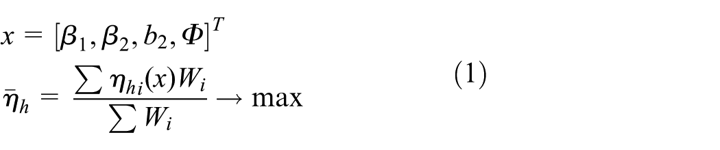
There are four control parameters, including blade inlet angle β1, blade outlet angle β2, blade outlet width b2, and blade wrap angle Φ.
Optimization model
The mathematical model for multi-condition hydraulic optimization for impeller blades of a mixed-flow pump is as follows


Model pump
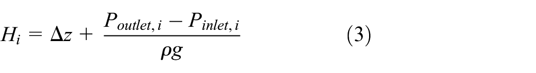
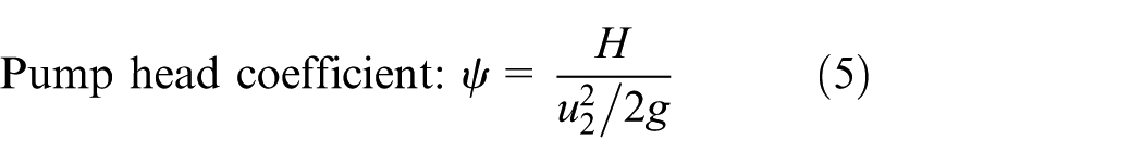
To facilitate the processing of numerical and experimental data, a couple of non-dimensional parameters are defined as

Original design of the model pump
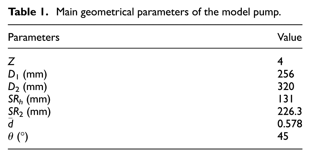
The traditional design method in mixed-flow pump is mainly based on one-dimensional design theory of pump. The design method is a combination of theory and experience, by calculating speed triangle in import and export of impeller, and with the means of the model conversion and so on, which is known as the speed coefficient method. The method is conducted for impeller hydraulic design of a mixed-flow pump, and the design flow rate Q is 1350 m3/h (φ = 0.154), the design head H is 14.5 m (ψ = 0.482), and the design rotation speed n is 1450 r/min, so the specific speed is 436.1. The main geometry parameters of impeller are shown in Table 1, and the hydraulic views of the impeller are shown in Figure 1.
Main geometrical parameters of the model pump.
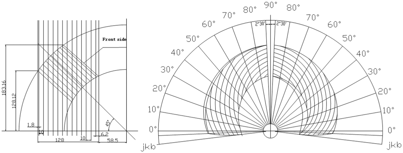
Hydraulic views of the impeller.
The processing of the original model pump
The structure of model pump is shown in Figure 2. Model pump is composed of the inlet pipe, impeller, impeller chamber, guide vanes, outlet elbow, shaft, and other components. Impeller inlet is connected with inlet tapered pipe; outlet of guide vanes is connected with elbow by angle of 60°.
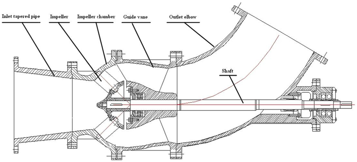
The structure of model pump.
The key components of model pump are impeller and guide vanes, and their quality will affect the pump performance and its operation stability. Impeller blades and guide vanes are mainly produced by precision casting before computer numerical control (CNC) machining and grinding. Figure 3 shows the impeller blades produced after machining.

The impeller blades after machining.
Test of the original pump
The test is operated on the hydraulic performance test rig of mixed-flow pump in Jiangsu University Research Center of Fluid Machinery Engineering and Technology, and it is carried out in a closed-loop test rig, as shown in Figure 4. The test rig is mainly composed of model pump set, electric valves, water tank, steady flow tank, electromagnetic flow meter, connection piping, and so on. The model pump is driven by a DC inverter, whose power is 110 kW. The main function of two steady flow tanks under test bench is to provide a steady flow for model pump. The flow rate of the pump can be regulated by the electric valve.

Schematic diagram of the test rig.
Figure 5 shows the performance curves of the mixed-flow pump under different angles of impeller blades. As demonstrated in Figure 5(a), the high-efficiency zone on the efficiency curve is very narrow when the blade angle is 0° (β = 0°). When the efficiency is above 82%, the flow rate coefficient is from 0.134 to 0.155, which means that the high-efficiency zone is only 0.021. At the design condition, the pump efficiency is 82.1%, and as demonstrated in Figure 5(b), when the blade angle is 0° (β = 0°), the pump head is 12.1 m (ψ = 0.402), which is 2.4 m (ψ = 0.08) lower than the requirements. Therefore, the original design cannot meet the design requirements, and the hydraulic optimization for impeller should be conducted.

Performance curves of pump model at different blade angles.
As can be seen from Figure 5, when the blade angle is 0°, +2°, and +4°, the efficiency is 83.5%, 85.18%, and 82.91%, respectively, while the corresponding flow rate coefficient is 0.145, 0.161, and 0.172. The result shows that with the increase in the impeller blade angles, the maximum efficiency point shifts to the large flow rate gradually.
Hydraulic optimization
Optimal design
Design of optimal scheme
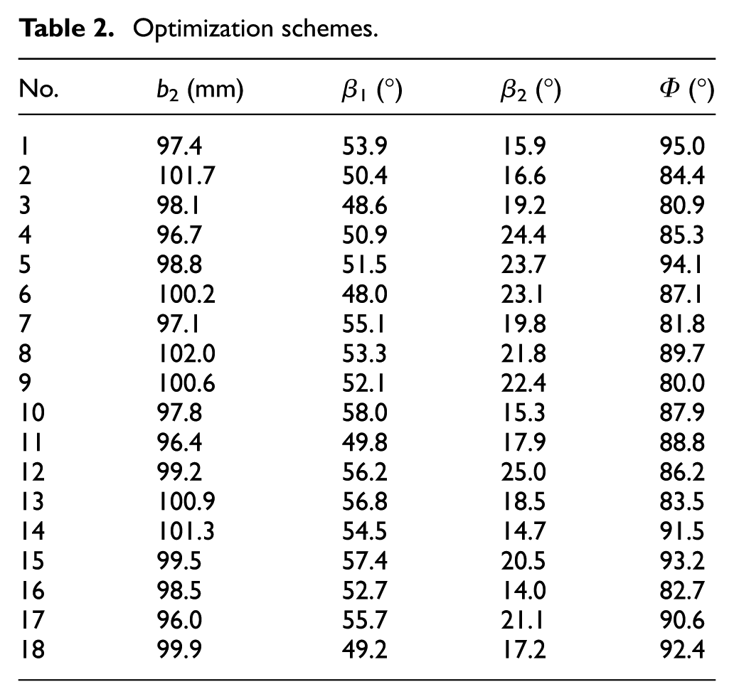
The optimization of the impeller blades is carried out when blade angle of mixed-flow pump is 0°. The initial values of design variables are as follows: β1 = 53°, β2 = 12.5°, b2 = 99.5, and Φ = 94.7°.
Each variable is in the following range: β1∈ [48°, 58°], β2∈ [14°, 25°], b2∈ [96, 102], Φ∈ [80°, 95°]. A total of 18 schemes are obtained with Optimal Latin Hypercube design (Opt LHD) method, and the parameters of each scheme are shown in Table 2.
Optimization schemes.
Optimization schemes at three operating conditions
The numerical optimization of mixed-flow pump is carried out at the following flow rate coefficients: φ1 = 0.137, φ2 = 0.154, and φ3 = 0.165.
Confirmation of weighted factor
In this research, ultra-transfer approximation method 19 proposed by Narasimhan is applied to determine the weighted factors of the objective function. According to the practical experience, the importance of φ1 and φ3 conditions is 0.9 times that of φ2. Finally, the weighted factors of each objective function at the flow rate of φ1, φ2, and φ3 are 0.321, 0.358, and 0.321, respectively.
Applicability of the turbulence models
Calculation method
The commercial code CFX is used to calculate three-dimensional turbulent flow in the pump. On the basis of average Navier–Stokes equations, the steady-state calculation for pump is conducted first. The inlet boundary condition is velocity inlet. The outlet boundary condition is pressure outlet. Rotating frame is used to consider the rotation of impeller, and other computational domains are in static coordinate. The wall is supposed to be no-slip solid wall boundary.
Grid generation
The quantity and quality of grids have important effect on the CFD calculations. In this article, the hexahedral structured mesh is applied in grid generation of the mixed-flow pump. In order to check the influence of the grid number on the results, four sets of mesh are employed to conduct a grid-independent check, and the comparison results are given in Table 3.
Comparison of grid independence.

The test head and efficiency at design condition are 12.43 m (ψ = 0.413) and 82.2%, respectively. The comparison between simulation results and experimental ones demonstrates that within certain grid number, simulation error decreases with the increase in grid number. When the grid number increases from 2,209,600 to 2,851,300, the deviation of simulation results changes little and basically stabilized. But the more cells need more computation resource and time. Therefore, the cell number of 2,209,600 is selected for numerical simulation. The computational domain and grid generation are shown in Figure 6.
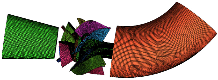
Computational domain and grid generation.
Turbulence models
Standard k-ε, re-normalization group (RNG) k-ε, standard k-ω, and shear stress transport (SST) k-ω models are employed, respectively, to calculate the inner flow in the mixed-flow pump at design condition with same the grid number of 2,209,600, and the simulation results and the test results are shown in Table 4.
Results of different turbulence models.
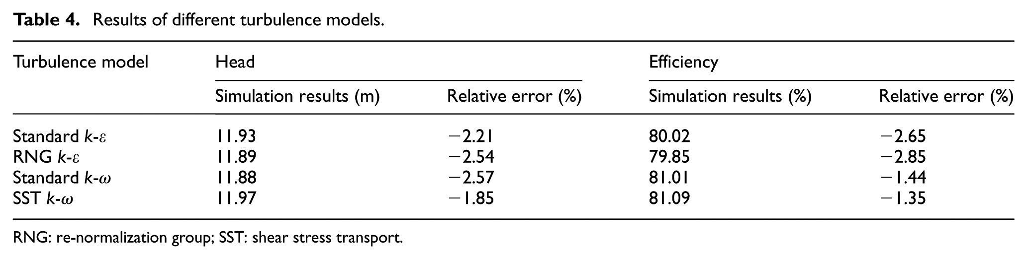
RNG: re-normalization group; SST: shear stress transport.
From Table 4, it can be seen that the head and efficiency obtained by four kinds of turbulence models are lower than the experimental values, and the relative errors are all less than 3%. It is also found from Table 4 that the head and efficiency calculated by the SST k-ω model are more close to the experimental values. Thus, this turbulence model is more appropriate for the simulation of inner flow in the mixed-flow pump.
Optimization results
Comparison of the results of optimization scheme
Table 5 gives the performance results of the mixed-flow pump predicted by steady simulation at φ1 = 0.137, φ2 = 0.154, and φ3 = 0.165.
The results of the optimization scheme under different flow rates.
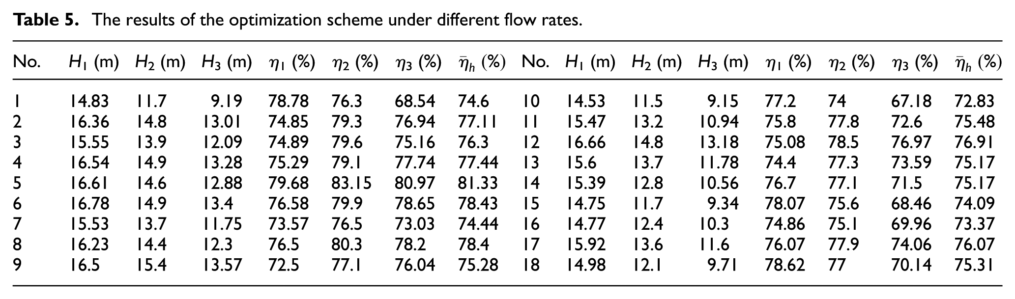
As can be seen from the prediction results, the maximum weighted average efficiency is from the fifth optimization scheme, and the value is 81.33%. The efficiency of the fifth scheme at the flow rate coefficients of 0.137, 0.154, and 0.165 are 79.68%, 83.15%, and 80.97%, respectively. Therefore, the fifth scheme is the best. In order to fully analyze the pump performance of the fifth scheme, a numerical calculation is conducted under the full flow rate of the pump.
Comparison of the inner flow numerical simulation results
The unsteady simulation of inner flow in the pump can provide better numerical simulation results.20,21 Therefore, in this part, the unsteady numerical calculation is conducted for the original design and the fifth optimal scheme, respectively, to compare the optimization results in detail.
Steady calculation results are applied as the initial condition for unsteady calculation. 22 The time step is 3.448 × 10⁻⁴ s, which means that the impeller rotates 3° in each time step. The total time is 0.2896 s, namely, the impeller rotates seven circles in the time. The results of the last rotation period are used for analysis. Figure 7 shows the velocity contour of cascade in impeller at the design condition, the original design is shown in Figure 7(a), and the optimization scheme is shown in Figure 7(b).

The velocity contour of cascade in impeller at the design condition: (a) the original design and (b) the optimization scheme.
From Figure 7, it can be seen that the high kinetic energy at impeller outlet gets bigger after optimization, which makes the pump head increase. Also, the curvature of the blade-type lines becomes smaller, and the adverse pressure gradient on the blade decreases. Therefore, the phenomenon such as fluid flow around the face, flow separation is unlikely to happen, and the loss of kinetic energy on the suction side is reduced. From the comparison between Figure 7(a) and (b), it can be found that the flow around the pressure side of blade becomes significantly smaller after optimization, and the kinetic energy loss decreases around the suction side because of adverse pressure gradient decrease.
Figure 8 shows the turbulent kinetic energy contour of cascade in impeller at design condition, the original design is shown in Figure 8(a), and the optimization scheme is shown in Figure 8(b). From the comparison between Figure 8(a) and (b), it can be found that the adverse pressure gradient of the blade reduces after optimization, and the kinetic energy loss decreases at suction side, so that the dissipation of turbulent kinetic energy decreases at the suction side.

The turbulent kinetic energy contour of cascade in impeller at design condition: (a) the original design and (b) the optimization scheme.
The prediction results of unsteady calculation
The prediction head and efficiency of the pump are the average results of the characteristics at each time step in the last period. Figure 9 shows the prediction results of the unsteady simulation for the original design and optimization scheme.

Characteristic of the original design and the optimization scheme.
From Figure 9, it can be seen that the performance of the pump is improved by the optimization scheme, and the efficiency is significantly improved, especially at large flow rate. The efficiency is up to 85.14% at the maximum efficiency point, which increases by 2.74%. Meanwhile, the high-efficiency zone becomes wider.
Experimental verification
Figure 10 presents the performance curves under different blade angles of the pump after optimization. From Figure 10(a), it can be seen that the pump efficiency is all more than 82% in the flow rate coefficient from 0.126 to 0.166 when the blade angle is 0° (β = 0°), which means that high-efficiency zone is 0.040. Compared with high-efficiency zone of 0.021 of the original design, the high-efficiency zone of the optimization scheme is increased by 0.019. The maximum efficiency point is at φ = 0.150, and the maximum efficiency is 86.6%, and as demonstrated in Figure 10(b), when the blade angle is 0° (β = 0°), the head is 15.7 m (ψ = 0.522). The head and efficiency of pump are 15.1 m (ψ = 0.502) and 86%, respectively, at the design condition. Therefore, the optimization scheme can meet the design requirements.

Performance curves of the mixed-flow pump under different blade angles after optimization.
From Figure 10, it can be concluded that after optimization the maximum efficiency points of the pump at the blade angle of −2°, 0°, +2°, and +4° are φ = 0.141, φ = 0.150, φ = 0.161, and φ = 0.170, respectively. When the blade angle of impeller varies from −2° to +4°, the maximum efficiency of the pump is always more than 84%, which indicates the performance of the pump is improved obviously by multi-condition optimization.
Conclusion
Through the analyses on numerical results and experiment data, the following conclusions can be obtained:
A multi-condition optimization design method for blades of a mixed-flow pump is developed in this article with the aim of maximum weighted average efficiency of pump, and the weighted average efficiency is 81.33% at three operation conditions of the mixed-flow pump. Furthermore, after optimization, the efficiency of the pump increases from 82.1% to 86% at design condition, which increases by 3.9%. Also, the high-efficiency zone increases from 0.021 to 0.040.
Through comparison of the inner flow numerical simulation results between the original design and optimization scheme, it can be found that the flow around the pressure side of blade becomes significantly smaller after optimization and with the decrease in the adverse pressure gradient at the suction side the kinetic energy loss decreases.
Footnotes
Appendix 1
Academic Editor: Mohammad Reza Salimpour
Declaration of conflicting interests
The author(s) declared no potential conflicts of interest with respect to the research, authorship, and/or publication of this article.
Funding
The author(s) disclosed receipt of the following financial support for the research, authorship, and/or publication of this article: The authors gratefully acknowledge the support of the National Natural Science Foundation of China (Nos 51209105, 51239005, and 51179075), the National Science & Technology Pillar Program of China (Nos 2013BAF01B02 and 2013BAK06B02), the Special Fund of Jiangsu Province of China for the Transformation of Scientific and Technological Achievements (No. BA2013127), the Science & Technology Pillar Program of Jiangsu Province of China (Nos BE2014116 and BE2014879), the Industry-University-Research Cooperation Innovation Funds of Jiangsu Province of China (Nos BY2014123-09 and BY2014123-07), the Priority Academic Program Development of Jiangsu Higher Education Institutions of China, and Graduate Student Scientific Innovation Foundation of Jiangsu Province of China (No. CXLX13_658).