
Abstract
A longitudinal force loading instrument for rails was developed to simulate the longitudinal temperature force of the rail of a ballastless track under different rail temperatures. The instrument comprised the rail, an end-fixing device, a temperature force application device, and concrete foundation. This instrument could simulate the longitudinal stress distribution of the rail under different rail temperature changes and analyze the correlation between the natural frequencies of the rail and the longitudinal stress generated by temperature variation. The result of the longitudinal stress distribution exhibits good agreement with the simulation results. In addition, the result of the dynamic characteristics of the rail demonstrates good agreement with the former conclusions. This experimental instrument can be potentially developed into a powerful tool for researching the rail features of a ballastless track under different temperature forces.
Introduction
The rail is a key component of rail transportation, and its integrity is critical to ensure railway safety. 1 A continuous welded rail (CWR) is commonly used in ballastless tracks; this rail exhibits the advantages of stability, low-cost maintenance, and long service life. However, CWR limits the free axial expansion of a rail. A large axial temperature force is produced when rail temperature changes. Rail temperature change is one of the dominant factors that affect the generated longitudinal force. 2 A high axial force may cause rail breaks or expansions, which can seriously endanger railway safety. Consequently, investigating the static and dynamic characteristic of rails for ballastless tracks under different temperature forces is becoming increasingly important. Several investigations on temperature force in railways have been performed in recent years. Numerical simulations on the temperature force in rails and experiments on ballast tracks3,4 have also been conducted or compared with previous literature. 5 In June 2012, a field test of the Rail-NT prototype was performed on the ballast track at the Transportation Technology Center in Pueblo, Colorado, in collaboration with the Burlington Northern Santa Fe Railway.6–8 For direct railway measurements,9–13 although existing methods exhibit a complex construction field, debugging work and measuring long-term temperature force change are the most difficult to conduct and exhibit poor reproducibility. However, field test on ballastless track with the operating 350 km/h high-speed railway is very difficult. Any changes on railway or installation on the operating high-speed railway rail may affect safety, which is strictly limited by the railway department. In order to study ballastless track rail of the high-speed railway, we established a practicable experimental instrument. Foundation analysis data were obtained using the instrument, and a finite element was used for comparison and analysis. The instrument satisfies the investigation requirements of the rail characteristics under different temperature forces.
Design of the experimental instrument
The experimental instrument mainly includes the rail, a track plate, an end-fixing device, a temperature force application device, and the concrete foundation (Figure 1). The instrument is set up according to TB10015:2012, 14 TB10621:2009, 15 TB10754:2010, 16 and Jiang et al. 17 The rail is a 60 kg/m standard rail. The temperature force application machine is an LG-900 rail-stretching device, which can simulate force. The track plate is a CRTS-1 slab ballastless track, which is used in the 350 km/h Harbin–Dalian high-speed railway in China. The rail is fastened by a fastening elastic rod at a pressure of 9.0 kN for CRTS-1. 16

(a) Experimental instrument for rail longitudinal temperature force and (b) the ballastless track section.
CWR limits the free axial expansion of the rail. A large thermal stress is produced when rail temperature changes. According to theory of mechanics of materials, the relationship between temperature force and temperature changes is expressed in equation (1) 1

where F, A, α, E, and ΔT are the applied thermal load, cross-section area, thermal expansion coefficient, Young’s modulus, and temperature change of the rail, respectively.
Concrete foundation
To simulate practical applications accurately, a reinforced concrete foundation was built (Figure 2) to limit the free axial expansion of the rail when temperature changes. Four M48 bolts were set to connect the end-fixing device to the foundation. These bolts were parallel with the rail and located at the same altitude of the neutral axis of the rail.

Steel frame of the concrete foundation.
End-fixing device
The end-fixing device was connected to the rail with a reinforced concrete foundation to prevent rail-free displacement (Figure 3). 18 Two M48 nuts were used to adjust backboard location, as shown in Figure 3(a). The backboard clung to the rail ends to prevent the rail from destroying the concrete foundation, as shown in Figure 3(b). A pull rod connected the rail with the foundation. Three φ32 holes of the pull seat and the through-hole of the rail coordinated with the M30 bolt. The locking nut (Figure 3(a)) was placed on the pull rod to fix the rail.

End fixing device: (a) adjust section and (b) lock section.
Longitudinal stress distribution test of the rail break
Setting the stress sensor on the rail
The stress detection method for rail temperature force is an important means to monitor railway safety. The stress sensors used in this study included resistance strain gauges and strain-sensing nodes. A total of 12 strain gauges were installed on the neutral axis of the rail along the longitudinal direction of the rail. The distances between the broken location and the 12 strain gauges were 0.6, 1.3, 2.5, 4.4, 5.7, 7.6, 9.5, 10.1, 11.3, 13.2, 15.1, and 15.8 m, respectively. Stress data can be collected from these positions. In this manner, the stress data of different positions were collected.
The rail break experiment was divided into six steps:
Step 1. The stress sensors are calibrated before deploying.
Step 2. The wireless sensor nodes are connected to the gateway.
Step 3. All the rail fasteners are released to discharge the internal stress of the rail.
Step 4. The rail is stretched to a specified pressure, and this pressure is maintained until the rail becomes stable to simulate rail temperature force.
Step 5. All the rail fasteners are locked, and the stress sensor values ε1 are recorded.
Step 6. The stretching machine is released, and the stress sensor values ε2 are recorded until the rail becomes stable.
Hence, the change in longitudinal strain was Δσ = (ε1–ε2).
Finite element analysis of the rail break
A three-dimensional (3D) finite model with an eight-node hexahedron element for a ballastless track was established for simulation using ABAQUS software. This model, which was based on the conditions of the slab tracks,7–10 considered the longitudinal resistance of the rail fastener but disregarded the dynamic characteristics of the rail. The rail pad was simplified as a rectangular block under the rail. In this model, longitudinal resistance and temperature stress were applied on the rail. One end of the rail was fully constrained to indicate the infinite condition of the ballastless track (Figure 4). The other end was released to reflect the rail break condition in Step 2 (Figure 4). The parameters used for this model, which are according to the industry standards in China,14,15 are provided in Table 1. The research model considered the longitudinal resistance of the rail fasteners but disregarded the dynamic characteristics of the rail. The rail fastener and the rail pad were simplified as rectangular blocks (Figure 4). The tightening torque of the fastener was equal to the pressure acting on the block. The simulation was divided into the following steps:
Step 1. The two ends of the rail are fully constrained.
Step 2. Rail temperature is changed, and the longitudinal stress of the rail is calculated after temperature change.
Step 3. One end of the rail is released.

Boundary conditions of the finite element model.
Components and parameters of the model.

Data analysis
Three conditions were analyzed in the simulation. Temperature changes were 7.8, 15.6, and 23.4°C, respectively. According to equation (1), the corresponding axial forces were 150, 300, and 450 kN. As shown in Figure 5, the horizontal axis is the distance between the stress sensor and the position of the rail break. The vertical axis is the longitudinal strain change before and after the rail break. As expected, the experimental and simulation results show that strain change decreases with increasing distance. The maximum value also increases with axial force. In Figure 5(a), the slope of two sensors fell within the increasing distance. The experimental results remain unchanged from a distance of over 13.2 m, whereas the simulation results remain unchanged from a distance of over 12 m. A similar variation tendency of the experimental results and the simulation results is presented in Figure 5(b) and (c). In Figure 5, the simulation curve of the temperature force distribution has the same trend with the experimental results. In Figure 5(a)–(c), the absolute difference of strain change between experimental value and the simulation value is less than 50e−6. Besides that, many points on each graph almost coincide. It is easy to infer that the simulated and experimental results match closely under different stretching force conditions. Conclusively, the strain change distribution of the experimental data is coherent with the simulation results. The results show that the proposed instrument and the procedures can be used to study the longitudinal stress distribution of a rail break on a ballastless track.

Comparison between the experimental results and the simulation results under (a) 150-kN stretching force, (b) 300-kN stretching force and (c) 450-kN stretching force.
Tests of rail vibration characteristics under different temperature stress values
Experimental steps
Tests on the dynamic characteristics of the rail were performed using the hammering method under different axial forces on the rail. The transient vertical vibration response of the rail after hammer knock was collected and recorded using an acceleration sensor placed at the top of the rail. By changing the axial force on the beam, the vertical vibration in the middle of the beam was measured, the vibration waveform was analyzed, and the relationship between longitudinal force and track vibration frequency was studied.
The experiment was divided into four steps:
Step 1. The stretching machine and all the rail fasteners are released to discharge the internal stress of the rail.
Step 2. The rail is stretched using the specified pressure, and the pressure is kept constant to simulate temperature stress in the rail.
Step 3. All the rail fasteners are locked once the rail is stable. The internal stress of the rail can simulate the temperature stress of rail, which is produced when temperature changes.
Step 4. The test is continued while keeping the pressure constant. The preceding steps are repeated until the vibration response data of the rail are obtained under different axial forces.
Data analysis
According to equation (1), the vibration of the rail under 180, 360, and 540 kN was calculated. The results are presented in Table 2. Dynamic characteristic experiments were performed on the rail under different forces (180, 360, and 540 kN).
Calculation results.

As shown in Figure 6(a), the frequencies exhibit nonlinear increase with modal numbers. The result shows that using the fitting curve with cubic polynomials will provide sufficient precision. In Figure 6(b)–(d), frequency increases correspondingly with axial force. Previous literature 19 had investigated on the vibration characteristics of CWR ballast track rail under different temperature forces. Similar conclusion of the relationship between temperature force and dynamic response was obtained from this experiment. As expected, the dynamic response of the rail is affected by temperature force. The frequency increases correspondingly with the force, and a high axial force results in high natural frequencies. When the modal of the vibration frequency is high, the influence of the force is considerable. All the results demonstrate that the experimental instrument and the procedures can be used in research on ballastless track dynamic characteristics.
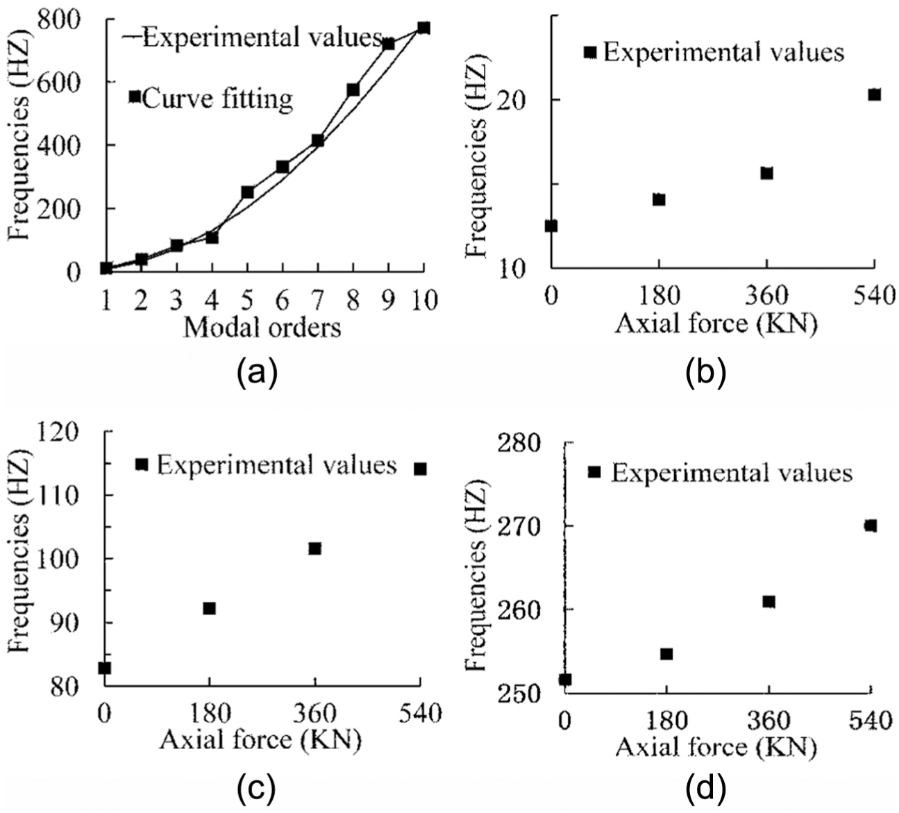
Change in frequencies: (a) tenth-order modes under non-axial force, (b) first-order modes under different forces, (c) third-order modes under different forces and (d) fifth-order modes under different forces.
Conclusion
Considering the difficulty in direct on-site measurement of ballastless tracks in high-speed railways because of installation conditions, time-consuming processes, and long distance monitoring, a rail longitudinal force loading instrument was designed and built for ballastless track research. The use of the instrument in studying the longitudinal strain distribution of rail breaks and rail dynamic characteristics under different temperature forces was aptly demonstrated.
Under different temperature changes, the strain change distribution of rail breaks showed that strain change decreased with increasing distance in both the simulation and the experiment. The law of experimental data exhibits good agreement with the simulation results.
Under different temperature changes, the vibration response characteristic of the ballastless track structure exhibited corresponding changes. An increase in temperature change may lead to an increase in the natural frequencies of the rail. When the modal of the vibration frequency is high, the influence is considerable.
These correlations are highly important in nondestructive measurements for rail safety monitoring in ballasted tracks. The experimental instrument provides a new, effective, and promising research tool to explore rail characteristics of ballastless track under different temperature forces.
Footnotes
Academic Editor: Crinela Pislaru
Declaration of conflicting interests
The author(s) declared no potential conflicts of interest with respect to the research, authorship, and/or publication of this article.
Funding
The author(s) disclosed receipt of the following financial support for the research, authorship, and/or publication of this article: This work was supported by the Twelfth Five-year National Key Technology R&D Program of China (Grant No. 2011BAG05B02-3), National Natural Science Foundation of China (No. 51475081), Science Fund for Creative Research Groups of NSFC (51321004), and Dalian Municipal Science and Technology Plan Project (2015A11GX002).