
Abstract
Generating a range of concepts is often a significant challenge for novice designers given their limited design experience and domain knowledge. This article develops a tool to support novice designers in formulating a design strategy for converting existing artifacts or mechanical objects into abstract representations. The app-based tool is aimed at supporting novice designers in (1) archiving existing artifacts, (2) converting artifacts into abstract representations for divergent activities, and (3) observing the kinematic movements of three-dimensional mechanical objects through augmented reality. An experiment conducted in 2014 investigated how the tool’s augmented reality function and the proposed strategy supported novice designers. A total of 13 second-year industrial design students generated 88 separate ideas. From 12 possible mechanical movements, four participants generated between 11 and 22 ideas each, while another five participants generated 1 or 2 ideas each. Each participant successfully proposed a concept that adapted the selected mechanism in response to a given problem in a given environment. Comparing pre- and posttest scores of each participant, 11 of 13 participants improved their knowledge of kinematic mechanisms. The results suggested that the use of the proposed tool and strategy has potential to help some novice designers explore new concepts and acquire related design knowledge.
Keywords
Introduction
Conceptual design is a process of exploring promising concepts (e.g. sketches) and involves concept generation, a divergent activity used to derive possible physical concepts, and concept evaluation, a convergent activity to evaluate these concepts.1–3 Divergent activity is seen as an improvement over sticking to an existing concept. 4 However, this presents a fundamental challenge to novice designers as their domain knowledge is too limited to broadly explore possible alternatives. 5 This article develops a tool and a novel design strategy to support novice designers in exploring possible design concepts from observing existing artifacts or physical objects.
A divergent activity is typically considered to be a synthesis or transformation step, such as transforming abstract solutions (e.g. functional trees) into detailed representations (a one-to-many mapping process). Unlike forward thinking that is commonly suggested for use in early design stages, the proposed design strategy represents simultaneous backward and forward thinking. A backward step starts by looking at existing artifacts or physical objects, rather than starting with the development of an abstract representation. Currently, four levels of design representation have been developed, that is, physical, generic physical, spatial, and topological solutions.4,6 Based on our previous approach, solutions at such physical levels can be converted into multiple abstraction levels. The more abstract a solution level, the less functional-, behavioral-, and structural-related information is present. The implicit information provides an opportunity to search for possible design alternatives that share explicit (unremoved) information. The strategy and the developed tool were assessed through a trial with 13 novice designers. We investigate whether the tool allows novice designers to effectively explore new design concepts while enhancing learning outcomes. Improvement was assessed based on the number and quality of concepts developed from the concept generation process, along with pre- and posttests.
The remainder of this article is organized as follows: section “Literature review” reviews the related literature, section “Supporting tool” describes the proposed tool, section “Evaluation” describes the experiment and results, and section “Results” discusses results and presents conclusions.
Literature review
Related work in approaches of abstraction, transformation, and augmented reality (AR) in learning is described.
Methods of abstraction
From existing artifacts or physical objects to generic physical elements
Existing artifacts or physical objects are those seen in our everyday lives. Due to various forms such artifacts take, developing a database of all existing designs is infeasible. Generic physical elements were proposed to approximate such designs. 7 The relation between a physical element and its associated generic physical element is shown in Figure 1. Each physical object consists of a generic physical element plus its specific descriptors. For example, in the case of a spur gear, the generic physical element is described with a plate as the form, a tooth as the motion interface, and a revolute pair as the support interface. The respective descriptors are a circle, a spur tooth, and a bearing. If we change the form descriptor to a rectangle while the remaining parts are kept unchanged, a rectangular spur gear is considered to be the physical object. The procedure for classifying standard objects into generic physical elements is to remove the specific descriptors of form, support interface, and motion interface from each standard object.

Physical element and its generic form, generic support interface, and generic motion. 7
From generic physical elements to spatial elements
An introduction to generic physical representations would allow designers to establish a relationship between existing designs or physical objects with their abstract representations. Applications of generic representations have been studied for conceptual designs in mechanical movements. 7 Generic physical objects can be converted into spatial elements by investigating their generic physical elements to identify their inputs and outputs. These inputs and outputs are combined with the adjoining objects. By applying a translational motion or rotational motion to the input point, one can derive possible kinematic behaviors of the output point. Considering the kinematic motion of the generic object at a particular point in time, the input and output can be represented in terms of force or torque. A spatial element is, therefore, obtained (see Figure 2). To convert the structural representation of objects into a length vector, a straight line is drawn between the input point and the output point. Having identified the length vector, a simplified vector can be assigned parallel to the i, j, or k direction.

Converting physical objects into possible spatial elements. 7
A spatial element has hidden information regarding the structure of its generic physical object. Therefore, an introduction to generic physical elements gives additional information for each abstract spatial element regarding its potential physical forms and interfaces and offers an opportunity to divergently explore generic physical objects. To start the exploration, applying translational or rotational input motions to a structure would result in the creation of various or similar behaviors. By applying the behavior of an abstract structure, from the structure’s behavior one can determine its possible functions, such as punching, pulling, leveling, cutting, and so on. Divergent thinking on each abstract spatial configuration with all its possible generic physical embodiments can be explored to generate alternative generic physical embodiments for a spatial configuration.
Approaches to transformation
Conceptual design is an early design process stage. At the conceptual stage, divergent activities are used to explore a broad range of concepts, so that better or optimal concepts will not be overlooked. Generally, different viewpoints have led to synthesis activities being classified into various theoretical classes.
One dominant approach is the systematic approach, such as those proposed by Pahl and Beitz 1 and Hubka. 8 This methodology helps designers identify functions in a functional structure and identify a number of working principles for each function. Transforming the functional solution to the next detailed level is a divergent design activity which raises alternative possibilities. Apart from functional view point of the solution, indirect synthesis can also start with abstract building blocks that represent intended motions or behaviors, and a set of potential concepts can be generated through a transformation process that combines a set of abstract building blocks and thus maps to a physical representation (such as a sketch). A building block thinking approach with rule development (e.g. composition or decomposition) allows for the development of computational tools which can raise efficiency for generating possible solutions in ways that would be infeasible through manual approaches. The collection of key concepts of building block is summarized below.
Physical building block
Examples include Kota and Chiou 9 and Li et al., 10 who developed two levels of building blocks—motion and physical. Physical building blocks describe a set of physical artifacts that embody the motion of building blocks. The link between problem requirements and their physical building blocks is explicitly described in terms of motion. Han and Lee 11 developed a similar concept as a computational framework. Physical building blocks can be developed in a more elaborate manner. For example, Roth12,13 developed a multiple-level solution representation to provide guidance to derive detailed designs from physical embodiments. Roth’s work differs from a computational approach in that it emphasizes the designers’ intuition over automatic concept generation. Building block approaches have also been developed to focus on components rather than mechanisms. Our previous work proposed a set of generic physical building blocks. Alternative mechanism concepts are synthesized through the combination of generic physical elements where rules of compatibility are defined in terms of contacting position, type of contact, and degree of freedom. Each generic physical element is defined from a generic point of view, and detailed descriptions in form, support, and interface are not considered.
Physical objects
Rather than generating them from the scratch, complete mechanisms can be retrieved by combining building blocks. Mechanisms and their kinematic behavior are first analyzed and stored in a library. The emphasis is to develop a complete set of existing designs. To retrieve alternative mechanisms, designers specify the required behavior in a time history of inputs and outputs and/or motion types. Computerized methods for retrieving mechanism concepts have been well developed by Murakami and Nakajima 14 and Gu et al. 15
Multiple levels of design solutions
Previous studies16–18 have contributed to the development of a computational approach that automates the generation of a range of physical concepts and allows designers to explore design space toward physical representations and backward to their abstract solutions. The function-based approach4,16 was started by the introduction of kind elements. Each kind element incorporates a certain class of physical laws and effects and has a unique building block feature with input or output (I/O). By following the defined rules of combination, the elements can be synthesized. This approach allows for the generation of a wide range of functional solutions which involve the transmission and conversion of mechanical forces and motions.4,16 For a given design problem, this approach can produce an exhaustive set of concepts in terms of their topological solutions. These are then offered to designers for exploration. Furthermore, spatial elements have been established with summarized information about the possible structure of the physical object, in terms of the directional and spatial aspects of existing embodiments at a specific time point. This allows designers to explore possibilities of spatial variants of a topological solution.4,16 Our previous study tested an abstract representation by means of hands-on experiments involving experienced designers. 16 It was found that the number and variety of solutions generated using this approach always exceeded the number and variety generated by designers. Furthermore, these abstract representations have been developed for a better elaboration. 7 A function–behavior–structure (F-B-S) model was proposed to link both the possible forms and interfaces representing the spatial element. 7
AR
AR is a means of establishing interaction between real and virtual images and objects in a three-dimensional (3D), real-time environment.18,19 Inserting virtual objects into authentic contexts creates a feeling of immersion which provides students with additional learning opportunities in an integrated learning environment. Chen and Chao 20 integrated concepts for reading instruction with marker-based AR to promote learner knowledge acquisition by printing images or icons in books; the user can activate these images to access supplementary information. Ozcelik and Acarturk 21 suggested that marker-based AR can be used as a supplement to textbooks to promote learning, and users were found to agree that marker-based AR is an effective way of providing access to supplementary reading materials. Previous studies have mainly focused on providing comparisons between textbooks and AR-based formats at the comprehension level. 22 However, few studies have attempted to use AR-based tool to support design activities. Given the range of views and findings regarding the introduction of digital technologies into design activities, there is still considerable space for discussion in this regard. Previous research on the user of AR in conceptual design has focused on the development of virtual prototypes for digital handheld products to enhance understanding of intended functions 23 and facilitate evaluation of visual appearance and user interaction. 24 AR has been used to develop virtual prototypes in combination with design models, such as in F-B-S modeling frameworks, to support design exploration. 25 The AR function of the proposed tool demonstrates mechanical movements through the kinematic movement of 3D objects. This allows the user to realize how the movement of a set of arranged 3D objects would be used to represent a perceived function. In summary, in design, AR has been used for the realization of 3D virtual models in real environments for the purposes of evaluation, representation, and exploration.
The supporting tool
System architecture
An app-based tool is developed to support novice designers. The current app prototype system is implemented in LiveCode programming language. 26 The system is exported as a standalone Android-based app for experimental purposes. The tool is developed to perform three functions: (1) to archive existing artifacts, (2) to convert the artifacts into abstract representations and to map these abstract concepts into their generic physical elements in terms of AR markers, and (3) to observe animated 3D mechanical movements through the AR function (see Figure 3(a)). The use case of this tool is to allow users for taking photographs of existing artifacts. The photographs are archived in the tool and can be selected to decide its possible spatial concepts. A spatial concept of the artifacts is an abstract representation and provides an opportunity for users to conduct divergent thinking activities. Also, this spatial abstract concept would be linked to our previously developed system to form an automatic computational system, FuncSION, 6 to exhaustively explore design alternatives.
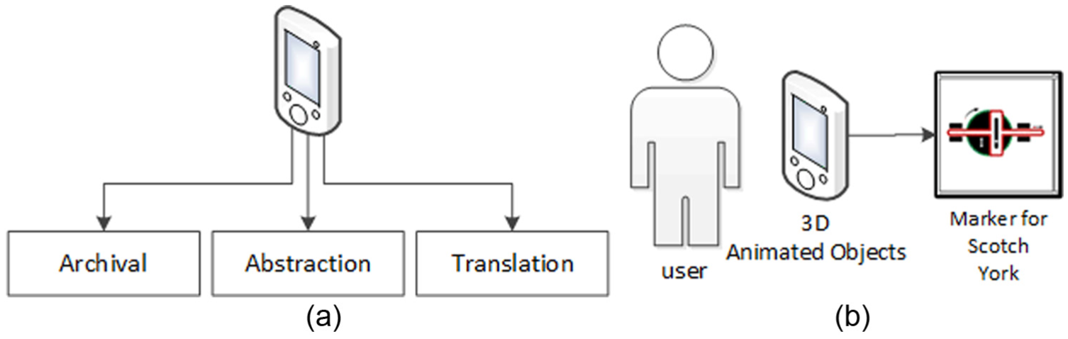
The architecture and use of the AR tool: (a) the major functions of the app-based system and (b) a simplified scenario of user–marker interaction.
As for the development of AR function (see Figure 3(b)), to represent the kinematic movements of 3D objects through any marker, geometrical objects are first built in the SpaceClaim computer-aided design (CAD) software. 27 The developed 3D objects are then imported into a 3D computer graphics program, called 3ds Max, 28 to further develop videos of the animated 3D mechanisms. AR-based 3D function is developed in the Unity game development platform. 29 The user can observe the component movement results from a given input motion in terms of the embodiment of each 3D object and the spatial configuration of each component, thus providing the user with useful functional, behavioral, and structural information. The programming tasks of this tool include allowing recognition of AR markers through an embedded camera, to link markers to their corresponding animation videos, and to develop rules to allow users to combine two or more markers in sequence so as to represent a set of interconnecting mechanisms. Currently, the AR-based 3D function is developed in Unity which is a standalone app. The integration of the app in LiveCode and the AR app is under development.
System functions
This first function (shown in Figure 4) is designed to archive existing artifacts or physical mechanisms observed in the user’s everyday activity. This allows the user to retrieve examples from a specific directory whenever necessary. Before photo taking, the existing object is allocated in front of the pad. The user then activates the app prototype to use the function “Take A Photo.” A message is then sent to activate the device’s embedded camera. Ideally, the user can take photographs of existing artifacts or other physical mechanisms such as those developed for educational purposes. When the user clicks the “Take a Photo” button, the user must first position the design artifact within the photo frame. The resulting image is then archived for future use.

Archiving the existing artifact or physical objects through taking a photograph or selection from the database: (a) click “Take A Photo” button, (b) place an existing objects with a relative size reference (a square), and (c) resize the picture for easy editing using the red dot.
Having photographed the observed object, the user then maps the object into some abstract solution. The photograph is proportionally resized using the scroll bar as shown in Figure 4. The user is asked to determine the input and output points. The simplified relative position between the output and input is described as one of the six offsets: i+, j+, k+, i−, j−, or k−. The example in Figure 5 uses the i− and j− offsets, which means that the output position is to the lower left of the input position. Having described the position, the user needs to specify the intended direction of the instantaneous inputs and outputs. Six directions are considered here: i+, j+, k+, i−, j−, and k−. In the example, the directions of the input and output are i− and j+, respectively. Having completed the first abstract element in terms of a bond-like structure, the second abstract element follows as shown in Figure 6. One of the spatial elements in the pre-determined library is mapped to represent the first part of the object. The remaining parts can also be mapped into their spatial elements. In this example, the two spatial elements are mapped to represent the observed structure.

Function of abstraction for converting a physical object into its spatial element: (a) start to click the input point using the red dot, (b) click the output points and decide the input kind, (c) click the input direction, and (d) decide the output kind.

Function of abstraction for completing two spatial elements: (a) complete the first element, (b) start with the second element, and (c) complete the editing of the spatial configuration.
Having mapped the abstract solution, the generic physical embodiments are retrieved and represented in terms of markers designed to approximate a simple schematic diagram with the form of a specific component, a joint of any two components, and its constraint. The rules for transforming any abstract solution in terms of functional elements into its physical embodiment have been developed in previous work. 7 The relation of each abstract solution with its physical embodiments considering the number of potential embodiments is one to many. In this article, we modify the resulting physical diagrams into system-recognizable markers as shown in Figure 7. Taking the button diagram as an example (see Figure 7(b)), the white diagram represents the first element on top of the dark diagram (the second element). The input and output motions are represented by black arrows. Having selected the marker, the user can observe the 3D kinematic movement of the linking mechanisms through the AR-based function. The use of AR-based 3D mechanisms offers several advantages. First, it is cost-effective compared to manufacturing physical objects for demonstration purposes. Second, the markers are much lighter and more portable than physical objects. Any modification of markers or the represented mechanisms can be accomplished through changing software parameters, rather than making new or modifying existing physical objects. The markers and the 3D objects are shown in Figures 8 and 9.

Translating a spatial configuration into its possible generic physical embodiments in terms of AR markers: (a) the specific spatial elements derived from the database and (b) potential generic physical mechanisms in terms of markers.
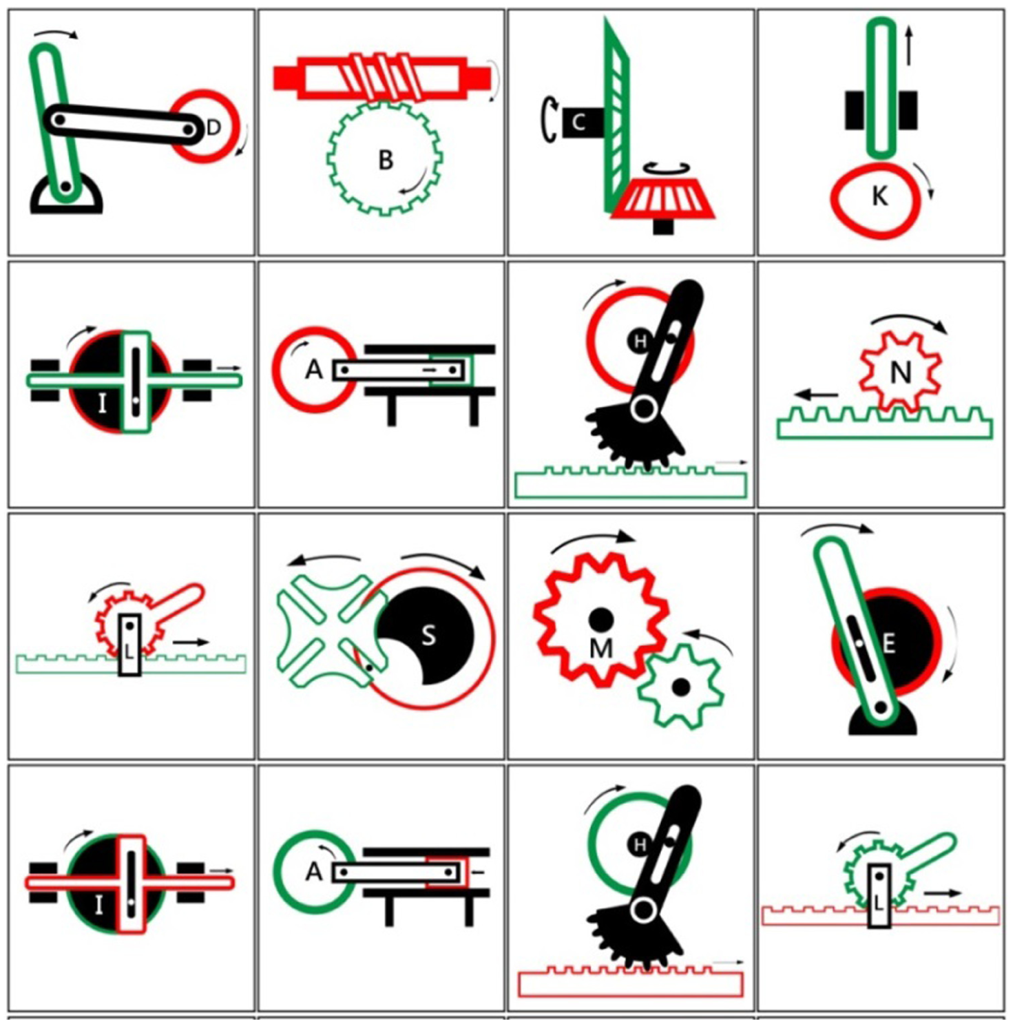
Sixteen markers designed and used in the experiment.
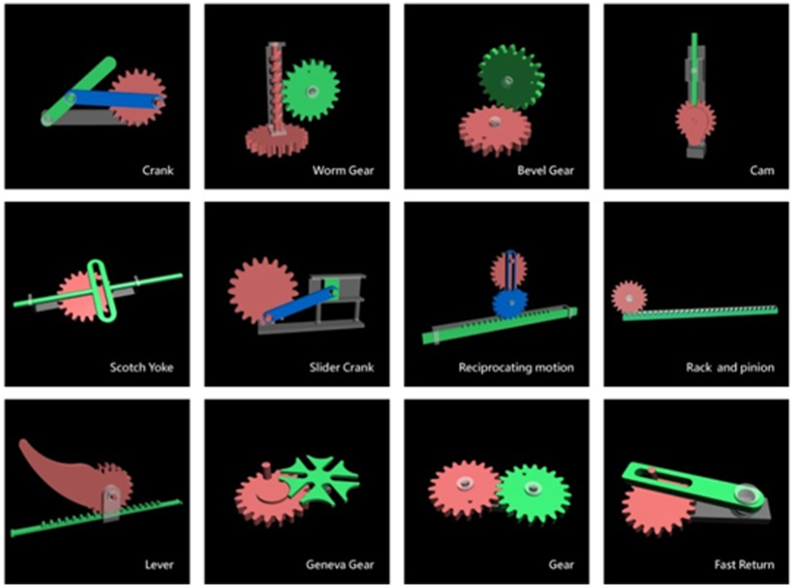
Twelve 3D objects used in the experiment.
Evaluation
Study design for evaluation
A total of 13 industrial design sophomores (10 females and 3 males) participated in the evaluation of the AR-based subtool. We sought to determine whether the tool facilitated concept exploration while improving learning outcomes. None of the participants had taken mechanical engineering–related courses in university. The tests were conducted as part of a compulsory course named “Fundamental Product Design.” The overall steps of the workshop are shown in Figure 10. Having completed the pretest (Figure 10(a)), one warm-up activity was conducted prior to evaluation. This was to provide participants with the opportunity to experience and be familiar with the conversion process of abstraction of an existing artifact and use their intuition to transform a specific generic physical mechanism into its possible alternatives with varying forms. Students were asked to generate alternative designs for a winged corkscrew with a lever rack-and-pinion mechanism. All participants completed the exercise, developing corkscrew variants. The summarized process is shown in Figure 10. An instructor demonstrated how a winged corkscrew works, emphasizing the sequence of processes in which depressing the lever lifts the cork. The generic physical embodiments were presented. The abstraction part was explained with a straight bar used to represent the lever. An example of a bee-like corkscrew design was given to the students to demonstrate a potential form variant but encouraged students to imagine a wide range of possible shapes. For example, the conceptual straight line could be used to represent many shapes of different lengths. Participants were instructed to sketch as many variants as possible in 60 min. Examples of the form variants are shown in Figure 11(b). Only a single mechanical movement was demonstrated with the real corkscrew; thus, participants did not need the support of the AR-based function. The activity followed the process shown in Liu et al. 30 which discusses the number and the divergence in styles in detail.
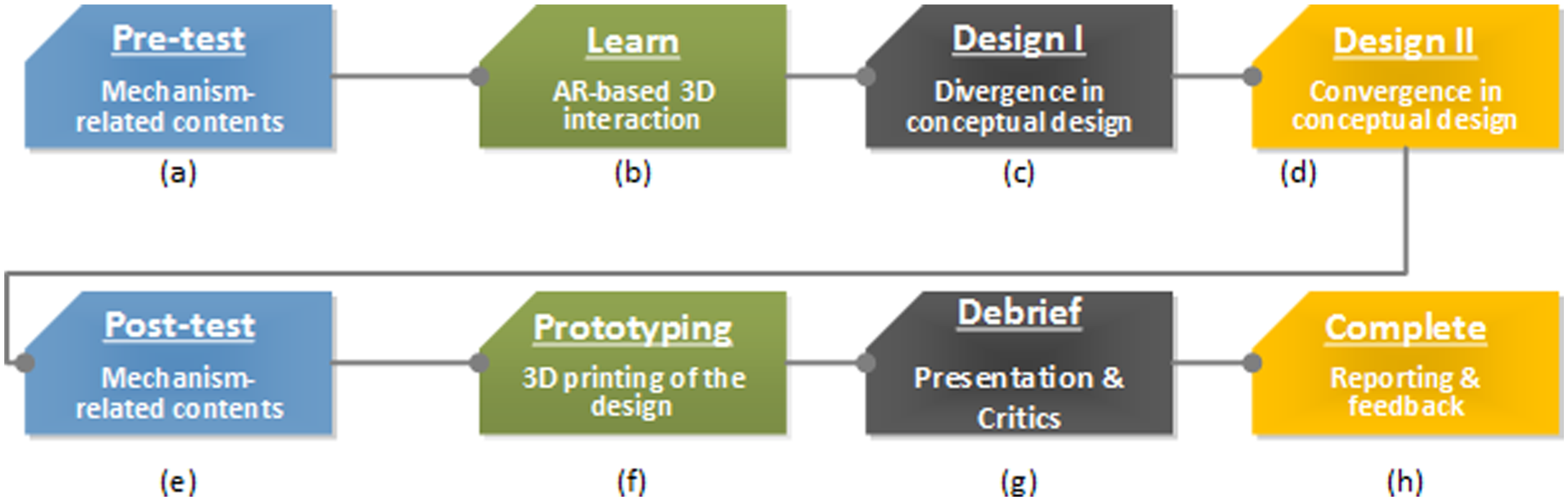
Workshop process design.

Example of design variants of a winged corkscrew: (a) the bond-like abstraction of a wind corkscrew and (b) examples of design variants in the pretest.
The evaluation provided in this article is a preliminary assessment of how the use of the proposed AR tool helps novice designers in formulating effective design strategies. Unlike the warm-up activity, in which learners examine one type of corkscrew and are asked to generate alternative designs for the same physical object, the activity presented in this article seeks to determine whether physical objects, rather than designed products, can support novice designers in generating design concepts to resolve perceived problems. The tool’s AR function helps depict a range of common physical objects (i.e. the 12 mechanisms). In addition, we also want to determine whether the design activity can help improve the learner’s domain knowledge. The post-warm-up activity includes a pretest to measure the learner’s knowledge of the physical objects involved, in which learners use the tool’s AR function to observe the various types of kinematic movement, conduct divergent activity, and select one or more concepts to incorporate into their design concepts.
Having completed the pretest, participants were tasked to learn the use of the tool’s AR-based 3D function. Due to limited resources, students were divided into four groups, with each group using a 7-in Asus Google Nexus tablet personal computer (PC) and 16 markers representing 12 commonly seen mechanisms. Four mechanisms are reversible; therefore, the input of each mechanism can be treated as the output and vice versa. As shown in Figure 12, each team participant was given the opportunity to use the marker to retrieve the 3D kinematic movements. Furthermore, appropriate connection of any two or more markers would result in a sequenced set of mechanical movements.
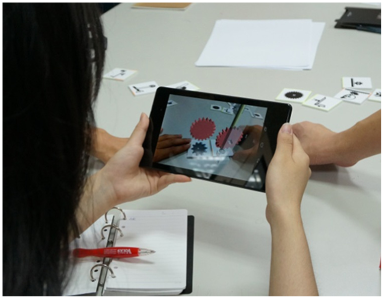
Snapshot of one participant using AR markers.
Each participant was given a table with a marker and its spatial configuration. Therefore, they were able to grasp the relationship of a mechanism concept (from the marker), the observation of the related 3D objects (from the pad), and the key working principle of the concepts (from the bond-like representation). Based on this understanding, they were asked to come up with multiple design ideas to be articulated verbally, rather than through sketches. The activity sought to link an intended function of a conceived product (e.g. paper punch) through the kinematic movement of a certain mechanism. Each participant was asked to develop design concepts based on these ideas with descriptions of a putative problem, provide sketches of a design solution, and describe the potential use and user of the product. Participants were given 3 days to complete the assignment.
Results
Results in divergent activities
This study assessed the results of divergent activities based on the number of ideas generated and the mechanisms selected for brainstorming. As shown in Table 1, the number of ideas generated ranged widely from 1 to 22. In the initial 2-h design exercise, no participants had previous experience of using an AR-based subtool, but all were able to use the tool to generate ideas addressing intended product functions through a spatial representation. Some participants were able to develop up to five mechanisms, with rack and pinion, level, and cam being the three mechanisms most commonly used in ideation, while the Geneva stop and Scotch York were the least commonly used. As shown in Table 2, the total number of initial concepts was reduced, each with a problem topic to be resolved, a target user group, and its schematic representations (i.e. sketches). Participants have shown to be able to propose a concept that adapted the working principle of the selected mechanism in response to a given problem in a given environment.
Number of mechanisms selected for divergent thinking and the resulting variants generated by the participants (N = 13).
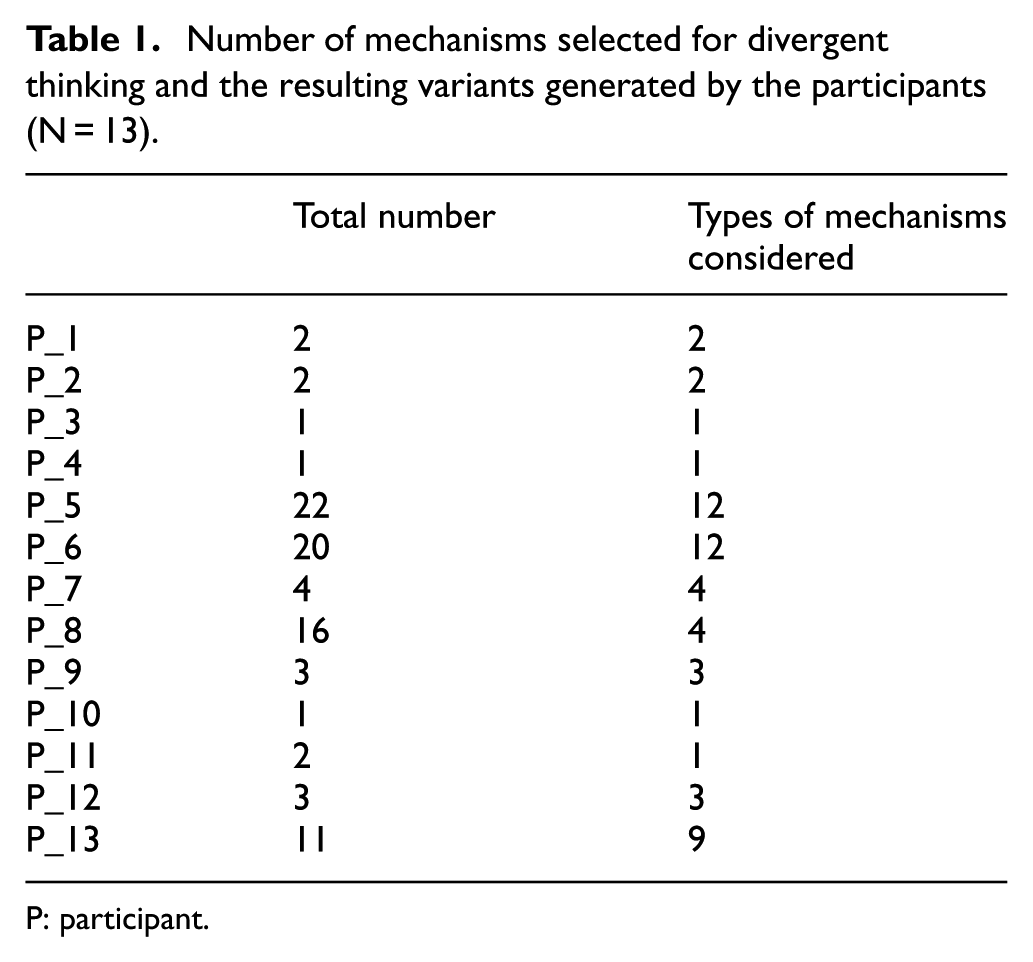
P: participant.
Mechanism and design concepts derived from the participants (N = 13).

P: participant.
Results in learning achievement
This study assessed learning achievement through a test with 20 questions, designed to test the participants’ knowledge and understanding in four aspects: the directional snapshot of a given mechanical object, the appropriate moving consequence of the components with a given input motion, the kinematic motion of the mechanism, and the appropriate geometrical support for a physical component. All questions were presented in a multiple choice format with four possible answers. Prior to use, all questions were reviewed by two subject matter experts. The pre- and posttest questions were all different, and a full score on either test was 20 points.
Table 3 shows that the pre- and posttest mean correction rates are 68.5 and 78.1, respectively. Furthermore, 11 of 13 participants improved their correction rates between the pre- and posttests. Three participants with low pretest scores (under 12 points) improved significantly in the posttest (up to 17 points).
Pretest and posttest performance (N = 13).
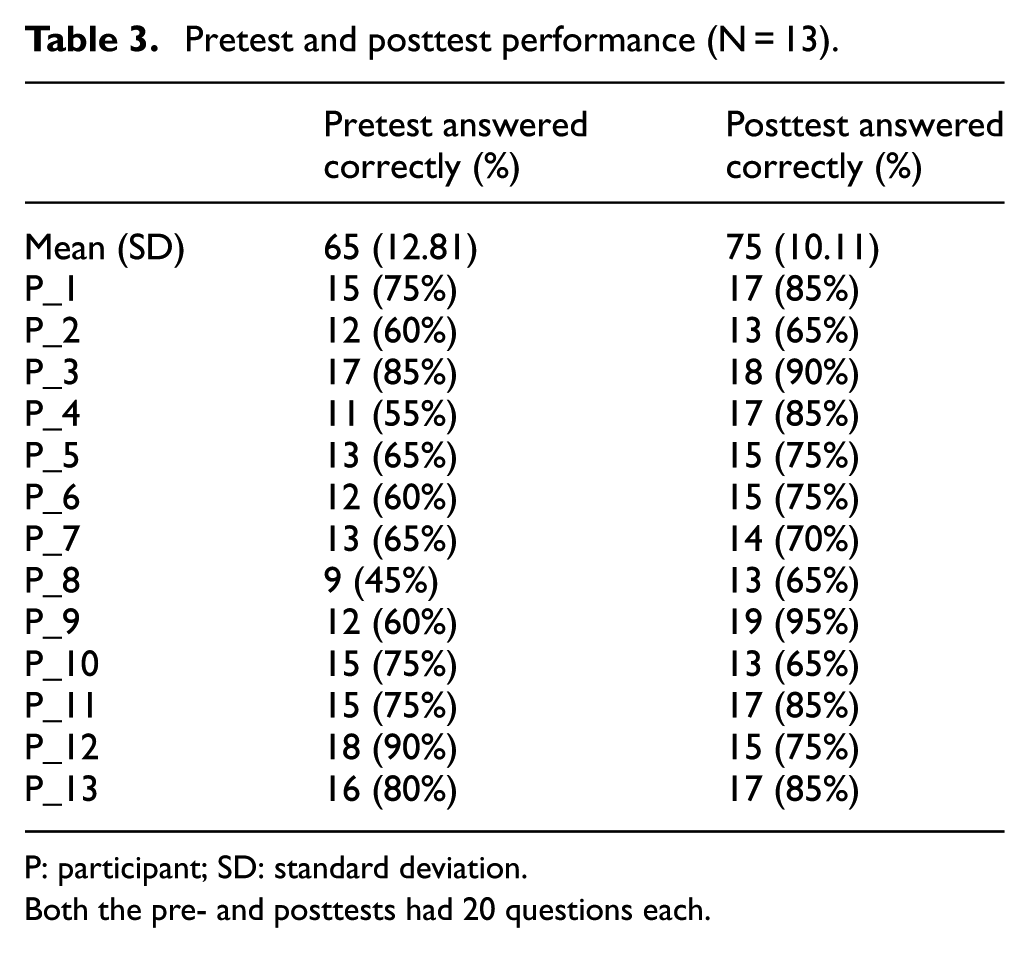
P: participant; SD: standard deviation.
Both the pre- and posttests had 20 questions each.
Discussion
This article investigates how novice designers would benefit from the proposed approach, given the constraints imposed by their limited domain knowledge and lack of relevant design experience. The challenge is to enhance both their understanding of design principles and design capabilities. The approach is meant to support novice designers to explore the solution space in a meaningful way. Furthermore, we developed a user-centric support tool to help users archive physical objects from their daily activities in the solution space, rather than using predetermined physical solutions. This feature negates the need to build an exhaustive library of existing designs.
The design strategy for the novice designers first looks at existing designs, thus backwardly linking to the corresponding solution abstraction (creating a bond-like structure) so as to allow users to explore shape and interface alternatives in a forward manner. The tool allows novice designers to gradually clarify and comprehend the functional, behavioral, and generic structural information of the existing designs. Furthermore, an abstract solution representation allows them to see things through different perspectives. This abstract representation provides an opportunity to conduct divergent activities when exploring various shapes, interfaces, and spatial possibilities at a detailed solution level. For instance, a typical corkscrew was used in the warm-up activity, with novice designers brainstorming possible corkscrew-design variants when investigating the movement (i.e. behavioral information) of this bond-like abstraction. Apart from existing designs, a class of mechanical movements represented as generic physical objects could also be used by novice designers to conduct divergent activities. The experiment involved 12 mechanical movements. Using the tool’s AR-based 3D feature provided better insight into the mechanisms, and the students were able to associate the existing designs with generic designs based on common working principles (e.g. a level rack and pinion). Again, these existing designs are first abstracted to allow participants to brainstorm possible physical and spatial possibilities. The differences in the corkscrew-design activities and the exercise in the experiment are considered in two aspects. First, the corkscrew designs involved the investigation of the physical variants of an existing corkscrew, which involves design activities in the configuration of a known design problem. Participants were familiar with using physical principles to represent ideas for further investigation of spatially and physically appropriate representations. The activities reflect the nature of conceptual design in which the design problem and solutions co-evolve, and the developed solutions gradually become more detailed.
All participants were able to generate ideas from the initial divergent activities. Individual students generated between 1 and 22 different concepts within the 2-h period. They were asked to start brainstorming from looking at the spatial representation, AR markers, and 3D physical objects. Based on an enhanced level of understanding for all 12 mechanisms, they tried to generate potential solutions for problems with which they were familiar or had personally experienced. This is considered to be the first problem-solution evolution for the designers. The process of ideation started with the observation of existing designs using the AR support tool. The simplified behavior and structure of existing designs were presented in terms of the spatial bond-like representation. From viewing the spatial solution, the transformation between a set of input–output characteristics (e.g. energy kind, direction, magnitude, and position) was taken to represent certain intended behaviors (viewed as functions) such as cutting, punching, and so on. Having identified the intended behaviors of a solution in representing different products, participants were asked to conduct a second round of problem-solution evolution. All ideas were clarified and pruned to better match the conceived problem. They were also asked to present sketches for designs to solve some everyday problems faced by a given type of target user. Participants derived at least two advantages from this exercise. First, they were able to quickly expand their relevant knowledge from the support tool. Second, new or innovative designs could be derived from existing artifacts or mechanical movements through the guided process.
The present research is restricted in several ways. First, given that no comparison group was conducted, the results of the test group do not directly demonstrate the effectiveness of the AR function support. However, divergent thinking is challenging for novice designers. The broad range of results for the divergent thinking activity, with some students generating up to 22 concepts while others generating fewer than 4 concepts, warrants additional comparative research to assess the effectiveness of the learning strategy using the tool. Second, the sample group consisted of a small group of participants, and future work should extend the use of the proposed tool to extended design cases. System improvements are needed to streamline the tool’s functions, including the extension of mechanical movements in the system library, and the integration of each function under a single technical architecture. Also, usability testing should be conducted for the proposed tool for different groups of target users. Future work will include a case study to determine the effectiveness of the design strategy using the AR tool.
Conclusion
This article investigates a key challenge in conceptual design—how to help novice designers generate potential concepts given their limited domain knowledge and lack of experience in using appropriate divergent thinking methods. We develop an app-based support tool to be used in conjunction with our previously developed method. Based on the number of concepts generated, along with pre- and posttests correction rates, experimental results shows some improvements in learning outcomes and concept generation. However, many other issues require further investigation. Follow-up comparative studies are required to provide an adequate evaluation of the tool’s effectiveness. The findings present three potential contributions to the literature. The computational application based on our previous design method is developed with the use of mobile computing and AR technology. Partial system features have been developed to a detailed level so as to enhance learning outcomes in university-level design courses. Finally, the results may provide insights for innovation in learning.
Footnotes
Academic Editor: Stephen D Prior
Declaration of conflicting interests
The author(s) declared no potential conflicts of interest with respect to the research, authorship, and/or publication of this article.
Funding
The author(s) disclosed receipt of the following financial support for the research, authorship, and/or publication of this article: This research was partly funded by the Chang Gung Memorial Hospital (CMRPD2C0022), Research Fund of Chang Gung University (BMRPD-67), and the Ministry of Science and Technology of the Republic of China (NSC 104-2221-E-182-049).