
Abstract
Determination of the handling properties of a vehicle may be restrictive in some situations. A vehicle model coupled with a driver model may be necessary and even unavoidable to analyse the real road behaviour in the most basic form. Therefore, a fuzzy logic–based controller has been investigated for potential application in modelling driver. Using some particular and limited number of information from characteristics of human driving operation, the model aims to provide any flexible vehicle path reliably. It generates the vehicle’s trajectory through a number of specified points through which the vehicle must pass. The controller was modified to account for peripheral vision characteristic of human eye, as an input. The simulation is carried out in the MATLAB© programming environment using a Simulink© vehicle model. Both longitudinal and lateral controls were applied in the study. This article adds novel approaches to the limited existing published work on driver steering model using fuzzy logic.
Introduction
Computer simulations have been an important part of the vehicle dynamics design process and the development/improvement of electronic control systems for decades. The implementation of the control systems such as antilock braking system, electronic stability programme, active steering, active braking and torque control and active suspension in the hardware are expensive and time consuming. Mathematical vehicle models can be used to estimate the performance of the proposed control system, and this process is highly cost effective, especially due to the minimised development time. However, a comprehensive vehicle model combined with a driver model is essential to be able to simulate many different scenarios. A control response of a driver model coordinated with visual stimuli and related to the vehicle dynamics control model can potentially make a correct simulation of the vehicle motion possible. 1
In the literature, a wide range of driver models employing various techniques can be found. From the driver modelling point of view, there is a general consensus that control occurs at two levels: 2 preview control, in which the driver anticipates the path ahead and makes an appropriate steering action based on knowledge of the vehicle dynamics, and compensatory control, where the driver compensates for errors in the preview control and for disturbances. However, according to Rix and Cole, 2 techniques for modelling driver behaviour are less well developed and appear to be inadequate for the reliable design of vehicles with good subjective handling behaviour. Limiting the determination of vehicle handling properties into the strict mathematical functions may be restrictive from the point of real-world road behaviour of the vehicle. Therefore, for the purpose of assessing the driveability, manoeuvrability and safety of the vehicles, the behaviour of the human driver has also to be included in the modelling approach to some degree. At this point, representing the human driver at any level in a model is an important point in making the vehicle characteristics in operation as realistic as possible.
Understanding and modelling the behaviours of human drivers are highly broad in scope. 3 A human driver considers imprecise data to make a concrete decision. An important outcome of imprecision is the possibility of assigning more than one symbolic value at the same time to the same variable with different degrees of truth in each of these values. Although human behaviour is not deterministic, it can be estimated for a normal person under certain constraints. 4 Many researchers studied on the human driver using a feed-forward or preview controller approach.5–8 Steering involves the driver looking ahead at the intended path relative to the car and somehow processing the preview information and the current motion data to yield the steering control inputs needed to make the car follow the path. 8
A trajectory following driver model allows the vehicle to be driven through a set path manoeuvre in differing states until the manoeuvre becomes beyond the abilities of the vehicle. The driver model would also react to the current state of the vehicle. This method models a real driver more closely and attempts to follow a specified path. The control algorithm adjusts to counter any undesirable dynamics, for example, excessive oversteer, and allows the model to be driven through a set path manoeuvre with varying velocity control. 9
In general, the associated driver models need to be more complex than the mathematical control models since at least some aspects of human cognition need to be considered. 10 The fuzzy logic has proven to be a very effective tool for handling imprecision and uncertainty, which are both very important characteristics of driving environments. 11 A nonlinear fuzzy logic controller can be used to represent driver behaviour by offering the ability to develop rules which make intuitive sense and can be expressed in linguistic terms. 12
Hessburg and Tomizuka 13 employed a fuzzy logic controller for vehicle lateral control on a full-sized test vehicle. The controller included a feedback module to infer control action from state errors, a preview module for preview information regarding upcoming road curvature and a gain scheduling module to handle the effects of the velocity of the vehicle. Cheng and Fujioka 14 developed a hierarchical model which has four individual layers such as decision making, task planning, manoeuvre, and action. They especially focused on the task planning and the manoeuvre, using the fuzzy logic as for basic decision making if there is a necessity to trigger the individual controllers such as gap control, lane keeping, speed tracking and lane change. The manoeuvres were applied using simple mathematical functions. Zeyada et al. 15 studied on a fuzzy logic driver model which was taking into account the road borders using five distance inputs and the angles between those. In the study, traction was neglected and the research was basically focused on to keep the vehicle on the road by applying brake input during the turn. Although the researchers claimed a human in the loop simulation, the explained principles of the input data collection were electronic sensory base. 15
Most of the driver models in the literature have been developed to control the lateral vehicle dynamics. Longitudinal dynamics is often simply kept to following a given or optimised speed profile, rather independent from the steering task of the driver, by focusing on the vehicle rather than driver. 16 This article, on the other hand, focuses on the control aspect of the driver and its subsequent conceptual or computer-based modelling, in general. 3 For the purpose, a vehicle model is used in conjunction with a fuzzy logic–based driver model to generate the vehicle’s trajectory through a number of specified points, which may be the coordinates of a real road. According to Lachenmayr, 17 participation in traffic is not possible without an intact central and peripheral visual field. Peripheral vision concept in the field of driver modelling and vehicle dynamics control has been investigated in detail, especially after the study of Donges. 18 According to Donges, 18 vehicle steering is based on information provided both far and near field. The main purposes of peripheral vision concept in driver modelling studies have been transportation safety (e.g. near object detection, lane keeping) and lane changing manoeuvres.12,18–22 By considering this, a preview control strategy was developed conforming to the nature of a real driver in some respects, such as peripheral vision of human eye. In our study, peripheral vision has been defined as a single point and called as ‘secondary target point’. Nevertheless, the input numbers, which represent the human cognition, were limited not to increase the complexity of the model. The simulation is carried out in the MATLAB© programming environment using a Simulink© vehicle model under fuzzy logic control to develop a trajectory through the specified points. The fuzzy controller can be used in conjunction with a vehicle model of any complexity provided it is available as a Simulink model. The complexity of the trajectory is defined by the specified points and their spacing, which can be used to describe road features such as corners and chicanes. The ability of a vehicle to negotiate the defined road features can therefore be simulated by testing how accurately the vehicle model/fuzzy driver combination can develop a trajectory through the specified points. The main contribution of this study to the field is the peripheral vision approach of the driver in trajectory following, introduced by the fuzzy inference system (FIS), which also permits the velocity change.
Tyre model
Tyre model used in this study is based on the works of Allen et al.23,24 This model uses experimentally provided data to derive analytical and nonlinear solutions to the vehicle dynamics simulations. The model presents the opportunity of using lateral and longitudinal tyre forces at the same time. Both the forces can be calculated for various longitudinal (S) and lateral slips (alpha) in a form which is normalised by µFz as they are presented in equations (1) and (2) 25
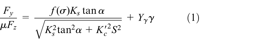

where µ is the slide friction coefficient, σ is the composite slip function, f(σ) is the force saturation function, Ks is the lateral stiffness coefficient and K′c is the modified longitudinal stiffness coefficient.
Vehicle model
An 8-degree-of-freedom vehicle model is used in this study. Basically, the model takes into account lateral, yaw, longitudinal and roll motions, enabling the inclusion of traction and braking forces on handling manoeuvres and additionally the dynamics of each wheel. Vertical load distribution for each wheel (Fz), rotational acceleration (


The longitudinal slip ratio S is defined as a function of velocity component in the wheel plane direction v and tyre tangential speed and depends on acceleration or braking.
For braking conditions


For acceleration conditions
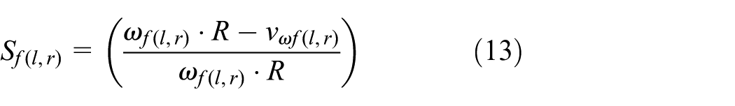
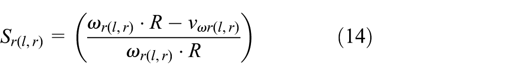


Equations (15)–(18) can be written in a more detailed form from Figure 1 as equations (19)–(22), respectively


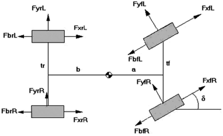
Forces acting on the vehicle – top view. 1
Fuzzy controller design
Compared to conventional control, fuzzy control (FC) can be strongly based and focused on the experience of a human operator, and a fuzzy controller can model more accurately this experience when compared to a conventional controller. 26 Therefore, the FC can be considered as a multi-input controller, similar to linear or nonlinear state-feedback controllers. 26
Mamdani-type FIS is preferable in FC instead of Takagi–Sugeno (TS)-type FIS, due to the rule structure, which is expressed in natural-language form. It is more intuitive to build the fuzzy rules so that the parameters can be determined later using genetic algorithms. Besides, the presentation of output membership functions (MFs) by the TS method requires much more parameters, which make the optimisation become more complicated and computationally intensive. 27 Therefore, a Mamdani-type FIS (Figure 2) was used to develop a driver model at some level, using any provided path coordinates, representing a real road. The model is to consider the severity of cornering and maintain a suitable vehicle velocity. As a result, the decision making includes basic steering, braking and acceleration actions in the model, and the variable velocity provided by the braking and tractive force inputs on the wheels is the main improvement to the previous model developed by Uzunsoy and Olatunbosun. 28 For the purpose, a Simulink model was developed by considering the basic vehicle dynamics model. The FIS has five inputs in total: two inputs are related to the vehicle orientation from the driver’s point of view (Error1 and Error2) and the rest is for the lateral acceleration, distance left to the first point which the driver aims (Distance) and the instantaneous longitudinal velocity of the vehicle. Three outputs are included representing the main control parameters of a real driver as the steering angle, braking and gas pedals. Meanwhile, the model does not claim to cover all the aspects of a human driver. The main goal is to introduce the basic human eye sight and the resultant reaction to the model by taking into account the both steering wheel and brake–accelerator inputs.

Fuzzy logic controller.
The control approach based on experience is acting in FCs by expressing the control requirements and elaborating the control signal in terms of the natural IF–THEN rules which belong to the set of rules. 26 Therefore, the rule structure is based on the relation between the antecedent and consequent. In Figure 2, (1) refers to the crisp inputs, (2) is the fuzzification module, (3) is the fuzzified outputs, (4) is the inference module including the fuzzy rules, (5) is the fuzzy conclusions, (6) is the defuzzification module and (7) is the crisp outputs of the fuzzy controller structure used in this study.
Peripheral vision approach
To achieve a trajectory, first, some representing coordinate points should be defined in earth-fixed coordinates. Then, the coordinates are transformed into the vehicle body–fixed coordinates during the simulation and the points defined, which the vehicle should pass through, are evaluated two by two, by taking into account a feature of the human eye. Considering a real driver’s driving behaviour, it is apparent that both steering and velocity control cannot be limited by a single target point. The two-point approach, which considers a near and a far point, is well known in the literature. Those two points can be switchable for the most convenient situation, even though, mostly the one is fixated. Therefore, at least in a particular moment or time period, ‘gaze’ action of the eyes is important in the presence of the both points. However, peripheral vision is a part of vision that occurs outside the very centre of ‘gaze’. 29 A driver can detect the tendency but not gaze on it. It is important for common driving tasks (e.g. changing lanes and merging into traffic). A real driver always searches for the following point of the first aimed point through the path, which is in peripheral vision that is not in focus, but that which the eyes can detect. This secondary target point actually exists in every moment of driving behaviour and is related to the ability of the eyes to notice the periphery in addition to the focal point. Both the first target and additionally the secondary target approach are the elements of a feed-forward controller in a vehicle system, in fact, an approximation for a real driver. According to Summala et al., 29 the usage of peripheral vision depends on the driver experience level. The more experienced the driver, the more information is provided by the periphery. In this study, secondary target point defines the orientation of the road, which the driver can sense in the periphery, and then, it becomes the new first target point ones the previous one is reached, during the automatised representation of the next two points. Therefore, the peripheral vision input supports the fuzzy controller by adding a human-like behaviour to it. Nevertheless, it should be pointed out that this is only an approximation of the real behaviour. In reality, eye movements can detect an infinite number of first and secondary target points. 17 Although the model works similarly, very limited numbers of points were aimed during the study.
During the simulation, if the first target is missed and left behind for some reason, then the second target becomes the first anyway. The fuzzy controller considers the MFs of the provided inputs and outputs for decision making. Figure 3 shows the target points which the vehicle must pass through in relation to its instantaneous position. The point O(x0, y0) represents the instantaneous position of the vehicle, with Ox and Oy representing the instantaneous forward and lateral moving axes, respectively. Points A(x1, y1) and B(x2, y2) represent the first and second target points which the vehicle must pass through, respectively. The angle between the instantaneous heading direction of the vehicle (Ox) and the direction of the first target point (OA) provides the input ‘Error1’ for the fuzzy driver (i.e. the angle AOx). ‘Error2’ is the angle between the current heading direction and the direction of the second target point (OB).

Vehicle body–fixed axis system and orientation inputs.
MFs and rule structure
A MF defines how each point in the input space is mapped to a degree of membership from 0 (non-member) to 1 (full membership). H− (High negative), M− (Medium negative), L− (Low negative), ZERO, H+ (High positive), M+ (Medium positive), L+ (Low positive), RH (Right High), RM (Right Medium), RL (Right Low), NC (No Change), LH (Left High), LM (Left Medium), LL (Left Low) and L/M/H (Absolute Values of Left, Medium and High) are all MFs used either in inputs or outputs of the FIS developed for this study. Each function possesses a degree of membership to which a weighting factor can then be applied depending on the vehicle’s position in relation to the target point, along with the appointed rules.
In a similar manner, MFs for the inputs Error1, Error2, Distance, Lateral Acceleration a(y) and Longitudinal Velocity are shown in Figure 4, while the output MFs of Steer Angle, Brake and Accelerator are shown in Figure 5. Due to its simplicity and giving promising results for most of the problems, triangular MFs were used except the Distance input. The sigmoid MF was preferred for distance input to provide three interacting but separate areas for three different actions at those parts using just two MFs. On the other hand, maximum velocity is used to limit the top velocity, and a singleton MF was used to define the limit. Lateral acceleration input was taken as absolute values into the FIS for the purpose of simplicity in fuzzy rule definition, by taking into account the steer angle feedback.
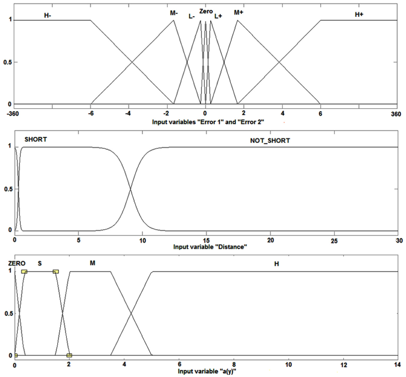
MFs of the fuzzy inputs: Error1, Error2, Distance and Lateral Acceleration a(y).

MFs of the fuzzy output steer angle, brake and accelerator.
Three basic outputs of the driver must be well synchronised to maintain the vehicle’s stability and route. When the process of decision making is considered, it should be as close as possible to human behaviour, and at this point, some criteria should be defined. These criteria must include the basic control parameters, realistically, while providing the velocity and steering outputs. For this reason, fuzzy rules as a natural part of the FIS were generated.
Each input should have its own MFs in the FIS structure which should match an output by these generated rules. For instance, steering angle output to be applied depending on the existing situation mostly depends on Error1 input in the fuzzy rule structure:
If Error1 Zero then Steer Angle is Zero
If Error1 L− then Steer Angle is LR
If Error1 L+ then Steer Angle is LL
If Error1 M− then Steer Angle is MR
If Error1 M+ then Steer Angle is ML
If Error1 H− then Steer Angle is HR
If Error1 H+ then Steer Angle is HL
Error2 input, which represents the secondary target point, also has a great importance in providing more realistic and satisfactory results from the model. However, Error2 is only taken into account when a certain distance is left to the first target point, in accordance with the human driver behaviour. The secondary target point prevents any sudden manoeuvres which may only be the actions of novice drivers. Then, the definition of ‘certain distance’ gains importance. If the action distance to the first target point chosen is relatively long, then it may result in too much vehicle deceleration. If the distance is very short, then the vehicle may traverse and improper velocity changes occur. The correct distance can be found by observing and classifying human behaviour. However, dependencies of this distance such as reaction times and psychological situations have not been studied, in detail, during this study. Here, it was decided that the secondary target point may be taken into consideration about in the last 10 m distance to the first target. In this distance, both first and second targets are considered. Therefore, down to 10 m distance, the fuzzy rules related to ‘Error1’ are considered for steering, braking and acceleration outputs. Then, ‘Error2’ is also used in decision making. If Error1 is too small during the last 10 m to the first target point, the accelerator will then be depressed to increase the speed. However, a high value of ‘Error2’ is going to decrease the resultant velocity and partly adjust the steering angle to improve the stability while aiming towards the next target. However, for a real driver, making a decision to change the velocity and steering of a vehicle also depends strictly on existing road conditions and the feel of control. Increasing lateral forces encourage the driver to decrease the velocity and/or steer angle if possible for safer handling. Thus, lateral acceleration, as yaw rate and so on, is a factor on decision making of drivers. Therefore, the model uses lateral acceleration a(y) with Error1, Error2, maximum velocity and distance as criterions for driver decision making. In this context, lateral acceleration is classified as Zero, Low, Medium and High in terms of fuzzy logic. Some selected fuzzy rules representing the roles of the lateral acceleration ‘a(y)’ and ‘Error2’ inputs are given as follows:
If Error1 is Zero, Error2 is M+, Distance is Short and a(y) is Zero, then Steer Angle is Zero, Accelerator is S and Brake is Zero;
If Error1 is Zero, Error2 is M+, Distance is Short and a(y) is L, then Steer Angle is Zero and Accelerator and Brake are Zero;
If Error1 is Zero, Error2 is M+, Distance is Short and a(y) is M, then Steer Angle is Zero and Brake is S;
If Error1 is Zero, Error2 is M+, Distance is Short and a(y) is H, then Steer Angle is Zero and Brake is M.
In the definition of road coordinates, there may be an infinite number of possibilities. However, in some cases, like long-distance straight-route travel, the coordinates, the related fuzzy rules and the base vehicle model must all be well considered due to the possible improper actions of fuzzy driver. For instance, the inputs, Error1, Error2 and a(y), can all be zero or near zero representing the straight-route travel. Then, the rules interpret this condition as ‘the velocity can be increased’, and in this way, there is no limitation in the rules to limit the velocity. Considering this situation, a limit value may be determined outside the FIS, within the vehicle dynamics model structure. To determine a limit velocity, a fuzzy input, namely, ‘Longitudinal Velocity’, having just a singleton MF, was also introduced. When the limit is reached, the condition of singleton MF is satisfied, and Accelerator Pedal input is released while the other cases are also considered. Similar but reverse application is done for deceleration without stopping.
Benchmarking
A benchmarking study was done using a well-known vehicle dynamics simulation tool called IPG CarMaker™. The software package includes also a driver model (IPG driver) which has preview point approach and also considers psychological studies and measurements from real test drivers to represent driver behaviour as realistic as possible.30,31 IPG driver has three classified default driver types such as defensive, normal and aggressive. The defensive driver was used for the simulations due to its closer results to the fuzzy driver model. Some of the comparative actions are presented in Figures 6–9. The comparison shows the single lane-change manoeuvre at 60 km/h initial speed. Steering wheel response shows that IPG driver reacts before the fuzzy driver, and it increases the angle gradually providing a sinusoid with the peaks around 25°–30°. Meanwhile, due to the late reaction of the fuzzy driver, the angle is increased with a higher acceleration resulting in higher steering wheel angle for the same route (Figure 6). Figures 7 and 8 show the accelerator and braking pedal inputs for fuzzy driver and IPG driver, respectively, while Figure 9 compares the longitudinal velocities provided by both the driver models. IPG driver did not use brake pedal during the whole manoeuvre due to slightly decreasing speed. Then, the driver accelerated the vehicle considering the initial speed and the possible reliable drive. Fuzzy driver, on the other hand, increased the speed slightly by continuously caring the route and the velocity. It is apparent that IPG’s defensive driver was more relax than the fuzzy driver. From the whole responses, the fuzzy driver’s reactions ended with the similar results, however, in a novice manner.
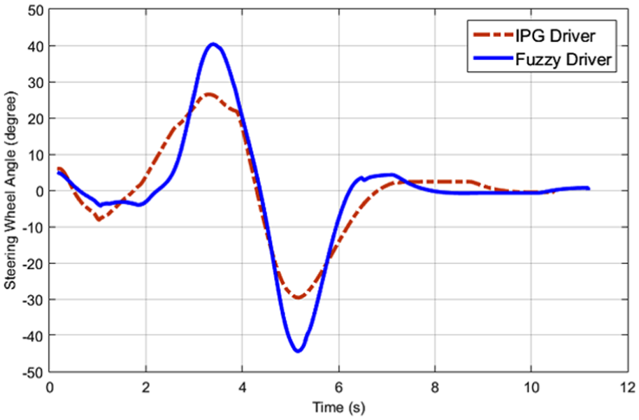
Steering wheel angle responses of IPG driver and fuzzy driver.

Accelerator and braking inputs of fuzzy driver.
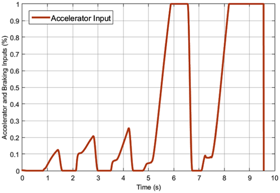
Accelerator and braking inputs of IPG driver.
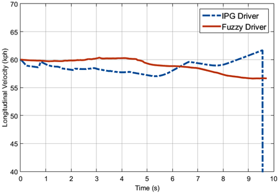
Longitudinal velocity responses of IPG driver and fuzzy driver.
Results and discussions
Path 1/double lane-change manoeuvre
A standard handling test track, which is standardised in ISO 3888-1:1999 (Test track for a severe lane-change manoeuvre – Part 1: Double lane-change), was used to test the efficiency of the fuzzy driver/vehicle control model. The trajectory was properly designed to the standard and represented by X and Y coordinates in the model. However, the intention was to observe the performance of fuzzy driver on a standardised path rather than performing a standard test. For the simulations, both tyre and vehicle parameters are provided from the literature 32

Some of the simulation results for this type of manoeuvre are shown in Figures 10–12. Simulations were performed at three different initial vehicle speed levels from 20 to 60 km/h. Figure 10 shows the path followed, while Figures 11 and 12 shows the longitudinal velocity variation and lateral acceleration level provided during the course, respectively. As it can clearly be seen, the velocity of the vehicle is increased up to the first lane-change point and slightly decreased when necessary (between 70 and 80 m distance) to keep the vehicle in position, which is an action provided by the ‘secondary target point’ (peripheral vision) approach. As a result, the manoeuvres are completed highly successfully in the given route. However, the level of slight lateral acceleration fluctuations, particularly at 60 km/h, shows that the driver tries to keep the vehicle on the ideal course.

ISO 3888-1 manoeuvre (path 1).

Velocity change for path 1.
Lateral acceleration for path 1.
Path 2/single lane-change manoeuvre
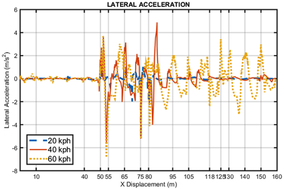
A lane change and longitudinal travel assessment are also shown in Figures 13–15. Similarly, simulations were performed at three different vehicle speed levels from 20 to 60 km/h. Figure 13 shows the path followed, while Figures 14 and 15 show the longitudinal velocity variation and lateral acceleration level provided during the course, respectively.
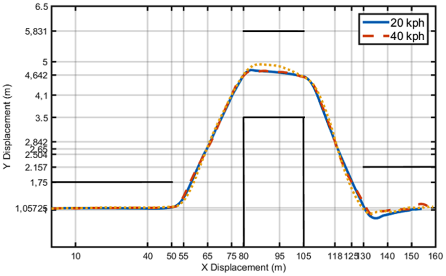
Lane change and longitudinal travel test manoeuvre (path 2).

Velocity change while following path 2.

Lateral acceleration for path 2.
As it can also be seen from path 1, in path 2 as well, the driver stabilises the vehicle especially between 80 and 95 m (Figures 14 and 15). At 60 km/h vehicle longitudinal velocity, up to 105 m distance, similar response can be observed due to the same path. Afterwards, even if the straight route, driver starts to struggle to keep the line at the same velocity, as seen in Figure 15. Figure 16, on the other hand, presents an example effect of the peripheral vision on vehicle dynamics response. At 40 km/h longitudinal velocity, it is obvious that the input provides better lane keeping and an overall manoeuvre. Defined vehicle travel coordinates (path 2) are given as follows


Lateral accelerations at 40 km/h with and without peripheral vision.
Conclusion
In this study, a trajectory following vehicle control model, based on preview control, was developed. Both longitudinal velocity and steering control provided a flexible test environment. The fuzzy controller representing the driver model including peripheral vision approach combined with longitudinal dynamics performed well enough in following a prescribed trajectory. However, it is obvious that tuning the MFs well depending on the experience is necessary to increase the robustness and reliability of the model, while modelling a human driver is also of importance for the future study.
Footnotes
Academic Editor: Francesco Massi
Declaration of conflicting interests
The author(s) declared no potential conflicts of interest with respect to the research, authorship and/or publication of this article.
Funding
The author(s) received no financial support for the research, authorship and/or publication of this article.