
Abstract
A fixed–fixed curved micro-beam resonator under the influence of harmonic electrostatic field is considered. Due to the presence of incompressible fluid between the micro-beams and the electrode, a squeeze-film damping affects the dynamic behavior of the resonator. The combined effect of curved geometry and fluid squeeze-film damping is investigated for micro-beams with concave and convex geometries. A reduced-order model is obtained through the application of Galerkin discretization on a coupled fluid–structure system composed of the nonlinear Euler–Bernoulli beam equation and Burgdorfer’s model for the neighboring fluid. The dynamic behavior is assessed by investigating the influence of squeeze-film damping on the linear and nonlinear frequency response and the maximum resonant deflection of curved up and curved down micro-beams.
Keywords
Introduction
When manufacturing microelectromechanical systems (MEMS), different etching mechanisms are utilized for removing deposited material on a substrate, leading to the formation of protruded and recessed micro-topographies. The recessed domains may take the shape of holes, cavities, and channels. These micro-features become air-filled gaps that serve certain design purposes. If a micro-machined device involves mechanically vibrating elements, its micro-gaps can contract leading to compressing contained air into smaller volumes. When air is squeezed in a micro-gap, it exhibits a damping effect that is proportional to the inverse of the air film thickness, a phenomenon known in the literature as squeeze-film damping (SQFD). This phenomenon was first theoretically predicted by Langlois 1 in 1962, and around 30 years later, experimentally proven by Buser and De Rooij,2,3 and later by JD Zook et al. 4 With the evolutional development of MEMS devices in various applications, evaluation of squeezed air film damping was under increasing focus by researchers to provide accurate evaluation of dynamic responses and design efficient control schemes.
An interesting type of air containing micro-gaps employed in microsystems is the spacing between two parallel protruded structural elements, one of which acts as a fixed electrode and the other functions as a resonating micro-beam. The air between the resonating micro-beam and the fixed electrode acts as viscoelastic element member, which resists compression. The efficiency actuation increases as the distance between the parallel structural elements decreases. In order to make highly efficient micro-resonators, one cannot avoid considering the SQFD effect in the design process.
This kind of MEMS resonators has been mostly modeled as a fixed–fixed (doubly clamped) micro-beam resting on thin film of air confined between the bottom surface of the micro-beam and the rigid electrode. The adopted analytical framework to study these fluid–structure interaction problems was principally based on the nonlinear Euler–Bernoulli beam equation that is coupled with the compressible or incompressible Reynolds equation, 5 assuming pertinent pressure values that prevent fluid rarefaction in the micro-gap.
Several papers have been published to consider the influence of SQFD on the dynamic behavior of the micro-beam from different perspectives.6–22 In all of these studies, the micro-beam was considered to be straight. The authors feel that there is a gap in the MEMS literature of studying the influence of SQFD on the dynamic response of curved micro-structures such as curved micro-beams and micro-arches. When researchers studied the dynamics of curved micro-structural elements without including SQFD effects, they found that these tiny structures could exhibit significantly different behavior than that of their straight counterparts. In particular, curved micro-beams tend to unveil snap-through instabilities and symmetric/non-symmetric buckling behaviors.23–33
In this article, the influence of SQFD on oscillations of a slightly curved micro-beam is considered. The initial shape of the beam is assumed to have a sinusoidal profile. The Euler–Bernoulli model is employed to investigate the vibration of the curved beam. The micro-beam nanotube is modeled as a doubly clamped curved structural member. A Galerkin approach is utilized to reduce the equation of motion to a second-order nonlinear differential equation, having quadratic and cubic terms in lieu of the geometric curvature and the mid-plane stretching. The micro-beam equation of motion is coupled with the Reynolds equation, for the air micro-gap between the micro-beam and the electrode substrate. A finite difference scheme is used for evaluating the pressure equation. Frequency response curves are numerically obtained for the cases of convex and concave micro-beams. The effect of increasing the curvature of the micro-beam starting on the vibration is reported and compared to the straight micro-beam.
Problem formulation
Let us consider a MEMS resonator, shown in Figure 1(a), made of a straight rigid electrode structure and a deformable curved micro-beam, with a gap in between that containing air. The initial shape of the micro-beam shown in Figure 1(b) is described as
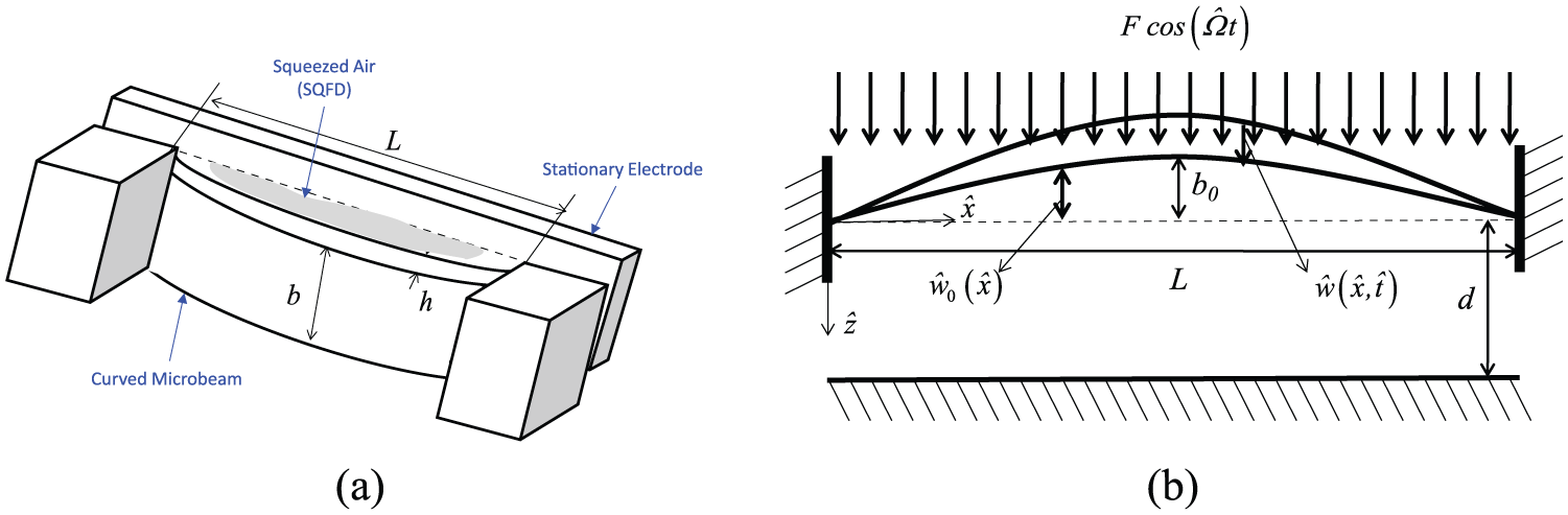
(a) 3D schematic drawing of the arch and (b) schematic of an electrically actuated clamped–clamped arch.
The considered micro-beam undergoes oscillatory motion that changes the micro-gap thickness d, leading to the redistribution of air pressure in the gap, and thus causes damping effect due to the thin film squeeze. It is, of course, assumed that air confined in the gap cannot escape from the sides. Therefore, a function

where
The one-dimensional force term
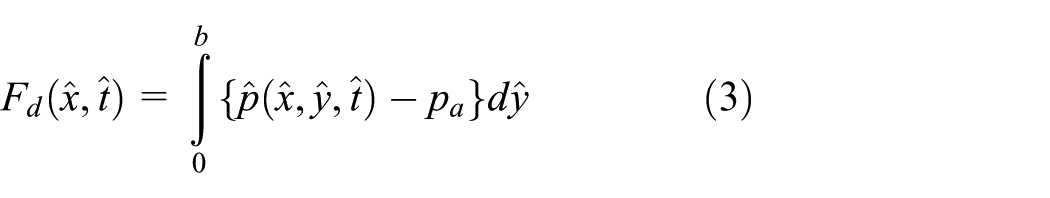
where
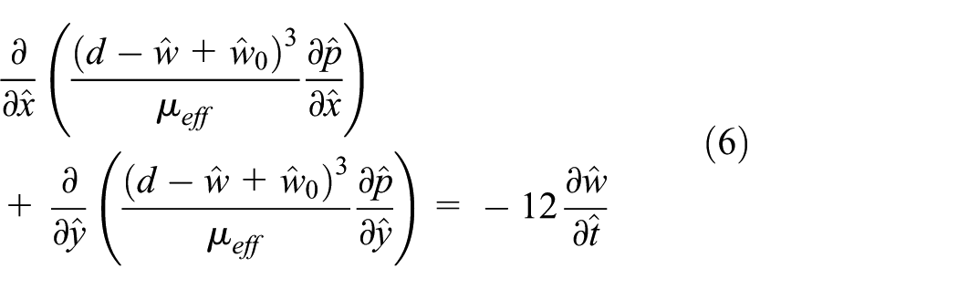
For slow viscous motion (where the Reynolds number is lower than 1), the pressure distribution

where

For a considerably small air-gap between the micro-beam and the rigid electrode, air trapped in this gap is assumed to be rarefied. The rarefaction effects can be accounted for by assuming slip-flow boundary conditions for the air flow in the micro-gap. A variable effective air viscosity
where the variable effective viscosity
In order to perform the analysis in dimensionless format, the following nondimensional variables

where T is a time constant defined by


where

In the above equations, one can identify the nondimensional variables summarized in Table 1.
Summary of the nondimensional variables used in the derivation.

The absolute pressure between the curved micro-beam and the straight rigid electrode can be expressed as

Note that this expression needs to satisfy the boundary conditions in equation (11). Hence,

Substituting equations (13) and (14) into equation (10) and integrating the resulting equation across the width of the micro-beam leads to
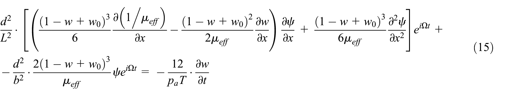
Assuming that the air-gap thickness to length ratio (d/L) to be less than 0.1, then, the term

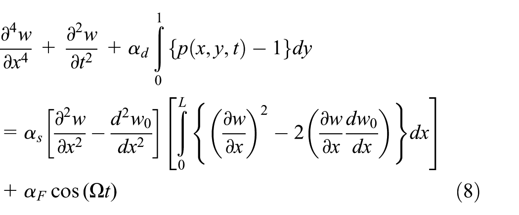
Hence, the micro-beam equation of motion (8) can be written as

where

Note that one can, in certain cases, use
Using a Galerkin approach for discretizing the equation of motion (17), let us assume

where

where
In order to get the reduced-order model (ROM), equation (19) is substituted in equation (17) and the resulted equation is multiplied by

where
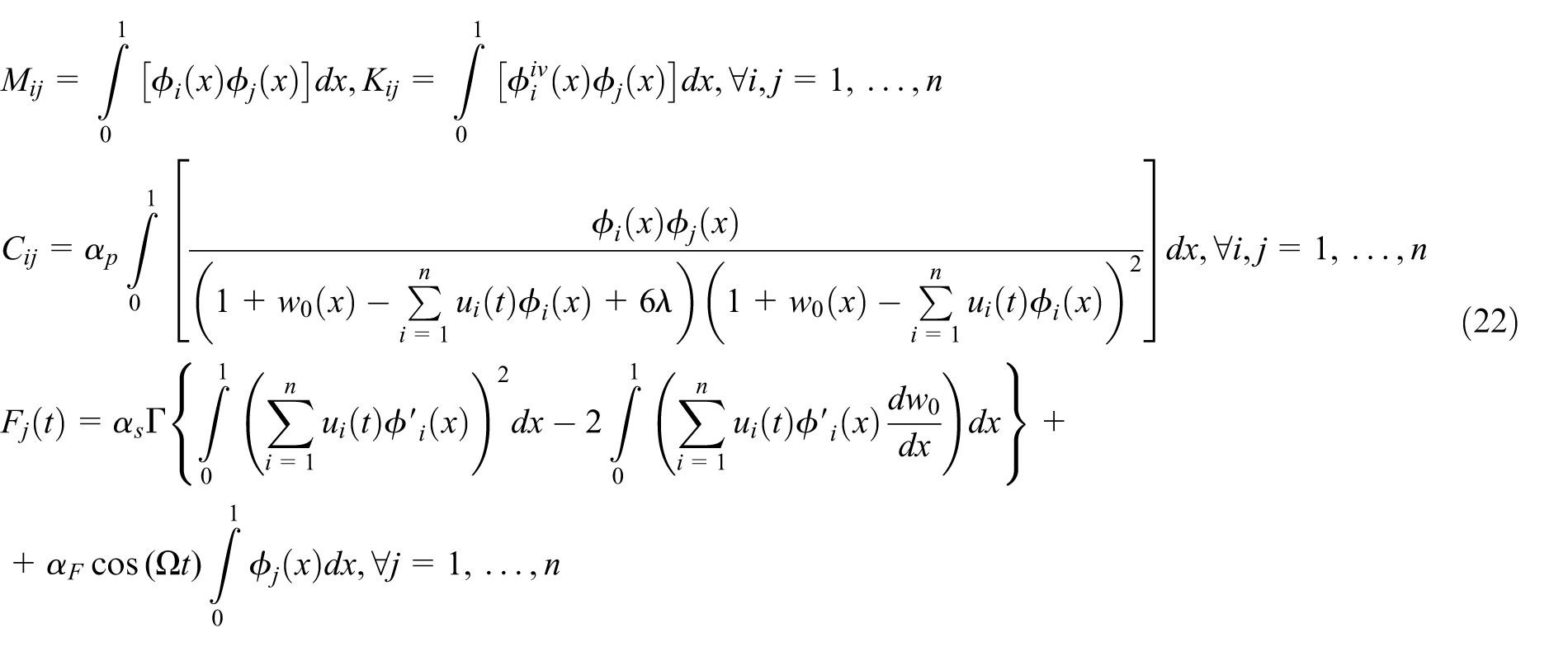
and

This above system of differential equation (21) describes the dynamic behavior of the micro-beam under the influence of the SQFD. A Runge–Kutta integration technique can provide a numerical solution of the system of coupled equations.21–23
Numerical results
As a case study for our numerical illustrations, let us consider a fixed–fixed slightly curved micro-beam made of silicon 24 (E = 166 GPa is the effective Young’s modulus, and ρ = 2332 kg/m3 is the mass density) and has a length of L = 1000 µm, a thickness h = 2.4 µm, a width b = 30 µm, and an initial rise b0 = 3.5 µm. The distance between the fixed rigid electrode and the micro-beam fixed supports to be d = 10.1 µm.
In order to verify the accuracy of the ROM, we compared a 3-symmetric modes ROM (equation (21)) to coupled equation of motion (8) with the pressure equation discretized using an explicit finite difference scheme. Figure 2 shows a very good agreement in predicting the frequency response between ROM and the coupled dynamics model.
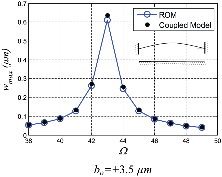
Simulated linear frequency response curves obtained using the long-time integration of the reduced-order model. Here, we assumed F = 0.0001 N/m to have a linear response
Figure 3 compares the frequency response of a slightly concave (raised up) micro-beam and its slightly convex (raised down) counterpart under a small external force with an amplitude of 0.0001 N/m and the two ambient pressure conditions of 100 Pa and 100 kPa. Both responses indicate linear behaviors. While the response of the concave micro-beam is almost the same under the influence of small and large ambient pressure, the response of the convex micro-beam is reduced significantly under the influence of a large ambient pressure.
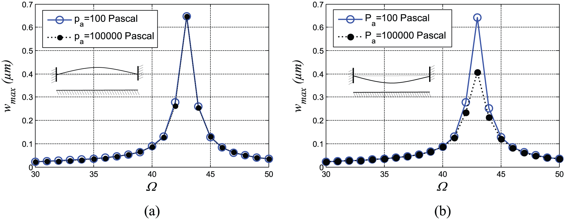
Simulated linear frequency response curves obtained using the long-time integration of the reduced-order model: (a) b0 = +3.5 µm and (b) b0 = −3.5 µm (F = 0.0001 N/m).
Figure 4 shows the variation in resonant deflection with varying ambient pressure at the mid-point of a straight, a concave (raised up), and a convex (raised down) micro-beam. In all cases, the amplitude of the external force is 0.0001 N/m. It is clear that the fluid pressure variation has slight effect on the maximum deflection of the straight micro-beam. The fluid pressure variation has almost no effect on the maximum deflection of the curved up micro-beam, while the fluid pressure variation has a clear effect on the maximum deflection of the curved down micro-beam. As the ambient pressure increases, the resonant deflection at the mid-point of the curved down micro-beam decreases in a nonlinear fashion.

Variation of the resonant peak deflection with the ambient pressure when the external force amplitude F = 0.0001 N/m. Resonance occurs at Ω = 23 in straight beam and at Ω = 43 in the curved beams.
Next, we examine the influence of the air micro-gap size on the dynamic behavior of the micro-beam. Figure 5 shows the variation maximum deflection on two convex (raised down) micro-beams, with different degrees of curvature, against the distance (d) between the straight rigid electrode and the fixed support of the micro-beam. As the size of the micro-gap increases, the micro-beam peak deflection nonlinearly increases, approaching a fixed maximum value. The micro-beam with a larger down curvature is subject to the influence of a thinner (stiffer) air micro-gap that exhibits less deflection.

Variation of the resonant peak deflection with the gap width. Here, we assumed F = 0.0001 N/m to assure a linear response at the resonant frequency
In all of the above presented examples, the external force applied on the micro-beam is chosen to be small to an extent that does not allow the micro-beam to reveal nonlinear behaviors. Let us now increase the applied external force amplitude to 0.001 N/m in one case and to 0.003 N/m in another case. When increasing the external force amplitude, nonlinear instability such as snap-through or buckling is shown. Our focus now will be on investigating the effect of nonlinear SQFD on the dynamic snap-through occurrence near primary resonance (excitation near the fundamental natural frequency). We can clearly see that increasing the forcing amplitude beyond the initial small value (F = 0.001 N/m) creates a frequency band where the micro-beam is forced to snap-through if it is operating within this band. Figure 6(b) and (d) show an example for the case of F = 0.003 N/m. In these figures, it is clear that the micro-beam vibrates in a snap-through motion, having large amplitudes compared to the case of vibration outside the snap-through frequency band. Comparing the dynamic frequency responses of a curved up micro-beam and a curved down micro-beam in Figure 6, one can clearly note that the effect of SQFD is minor on the nonlinear dynamic response of the curved up micro-beam. The effect of SQFD is prominent on the nonlinear dynamic response of the curved down micro-beam when it undergoes the snap-through instability.

Simulated nonlinear frequency response curves obtained using the long-time integration of the reduced-order model: (a) without snap-through (F = 0.001 N/m) and (b) with snap-through (F = 0.003 N/m) for b0 = +3.5 µm and (c) without snap-through (F = 0.001 N/m) and (d) with snap-through (F = 0.003 N/m) for b0 = −3.5 µm
The presented examples aim at providing MEMS engineers with prediction mechanism of what dynamic behavior to expect when designing micro-arches. MEMS arches are already being manufactured and encapsulated at low values of pressure to act as resonators and radio frequency (RF) switches.
Conclusion
The vibration of curved beam under the effect of SQFD was investigated using the Euler–Bernoulli beam model coupled with the Reynolds equation accounting for a variable effective viscosity. Galerkin method was used to discretize the governing equations and an ROM was obtained. The frequency response of the beam was obtained for various micro-beam configurations. It was shown that the SQFD effect was evident on the frequency response and the snap-through values curved down (convex) micro-beams, while it was less noticeable in the case of curved up (concave) micro-beams. The size of air micro-gaps was found to influence the peak resonant values of micro-beams.
Footnotes
Academic Editor: Xiaotun Qiu
Declaration of conflicting interests
The author(s) declared no potential conflicts of interest with respect to the research, authorship, and/or publication of this article.
Funding
The author(s) disclosed receipt of the following financial support for the research, authorship, and/or publication of this article: Research support offered by King Fahd University of Petroleum and Minerals (KFUPM) is acknowledged.