
Abstract
Transmission system is a crucial precision mechanism for twin-screw chemi-mechanical pulping equipment. The structure of the system designed by traditional method is not optimal because the structure designed by the traditional methods is easy to fall into the local optimum. To achieve the global optimum, this article applies the genetic algorithm which has grown in recent years in the field of structure optimization. The article uses the volume of transmission system as the objective function to optimize the structure designed by traditional method. Compared to the simulation results, the original structure is not optimal, and the optimized structure is tighter and more reasonable. Based on the optimized results, the transmission shafts in the transmission system are designed and checked, and the parameters of the twin screw are selected and calculated. The article provided an effective method to design the structure of transmission system.
Keywords
Introduction
Twin-screw chemi-mechanical pulping equipment is a new type of technology for pulping in recent years. Using the technology, raw materials can be processed into fiber like velvet with little being cut off and pulped with high concentration. This kind of equipment also meets the requirements of environmental protection. The transmission system, which transmits accurate motion and power to the twin screw, is one of the most important mechanisms for the equipment. Hence, making the mechanism design reasonable is a crucial problem. If the volume of the mechanism is smaller, and the weight is lighter, the structure will be more compact, and installation will be easier. In order to resolve that problem, it is needed to optimize the structure of the transmission system.
There are a lot of traditional methods applied in optimization. The traditional methods of solving multi-objective problems are to turn it into the single-objective problem. However, traditional optimization methods are principally gradient-based and deterministic, with a high risk of getting trapped into a local optimum. 1 That is the disadvantage of traditional methods. With the development of artificial intelligence in recent years, there have been some intelligent optimization algorithms, such as genetic algorithm,2,3 ant colony algorithm, 4 and neural networks algorithm5–7 applied in different areas. The genetic algorithm has been applied in some simple structure optimization. But there are very few researches which applied the genetic algorithm in the field of complex transmission system. This article establishes the complex optimization model to optimize the system and ensures the system volume more compact and lighter. Through genetic algorithm, the transmission system gets global optimal result rather than local optimal result.
In this article, the optimization model of transmission system volume is established first. Then, according to the practical situation and analysis, boundary constraints and mechanical constraints are introduced to make sure that the system can work well. Finally, the optimization process based on genetic algorithm is simulated. The simulation results show that the original design of transmission system is not the optimal solution, and the optimized results can make the volume more compact and weight lighter. Based on the optimized results of transmission system, the transmission shafts and screws are designed and checked. According to the axial and circumferential orientation, the structures of the shafts are designed at first. To guarantee the safety of the shafts in working conditions, the strengths are checked. The results showed that the shafts are safe.
Brief description of genetic algorithm
Genetic algorithm is in the simulation of biological genetic and evolutionary processes of natural selection, natural genetic reproduction, the phenomenon of crossover, and mutation in natural environment.8–11 Genetic algorithm is also a global probability search algorithm which can automatically acquire and accumulate the knowledge of the search space in the search process and adaptively control the search process. Hence, compared to general algorithms, genetic algorithm can handle multi-objective resolution effectively. Multi-objective problem can be written as below


where variable x is the objective vector,
We can draw the flow chart according to the genetic algorithm process, as shown in Figure 1.

The flow chart of genetic algorithm.
Optimization of transmission system based on genetic algorithm
The original design of the transmission system is shown in Figure 2. The transmission system adopts helical gears as its units to make the move stable. The structure of the system is single box with four axes marked with A, B, C, and D. This structure needs to be optimized. The structure meets the requirements: the speed of the input axis is 1440 r/min, the speed of the output axis is 600 r/min, the output torque is 850 N m, the distance between axis B and axis D is 63 mm, the transmission ratio of gear 1 and gear 2 is 2.4, the ratio of the rest of pair gears is 1, the working life is 15 years, and the system works for 300 days every year and 16 h each day.

The simplified structure of transmission system.
The article takes the volume of all units in the transmission system as the fitness function and takes the 12 parameters as the chromosome, such as normal module, helix angle, and gear width coefficient. The specific optimization process is as below according to the flow chart of genetic algorithm in Figure 1.
Encoding
In order to make transmission stable, all the transmission units are helical gears. Helical gears have more parameters than normal gears. Correspondingly, that makes it harder to optimize the volume. The gear parameters determine every performance and geometrical relationship of the transmission system, so according to the meshing relationship, 12 parameters of the three gear pairs are selected to aim to be the optimized objects. Hence, encoding is designed as the chromosome,
All the other gear’s parameters of the system can be calculated by the 12 parameters as shown above.
Establishment of fitness function
The article establishes the sum of all volumes as the fitness function, which is the objective function. The function is indicated in equality (1)

where
Establishment of constraints
The transmission system needs to meet many kinds of constraints. There are three primary categories:
Constraint of dimension boundary. The constraints include the boundary of gear tooth number, gear width, helix angle, and so on.
Constraint of meshing principle. The constraints include avoiding undercut, prime number for the meshing gears, and so on.
Constraint of mechanical performance. The constraints include the gear fatigue strength of the surface contact and the tooth root bending.
Hence, below is the process of analysis.
The normal module is bigger, the distance between gear teeth is bigger, and the gear is thicker. Hence, the performance of bending resistance becomes stronger. The module is standardized as: [1.5, 1.75, 2, 2.25, 2.5, 2.75, 3, 3.25, 3.5, 3.75, 4, 4.5, 5, 5.5, 6]. Among those numbers, [1.5, 2, 2.5, 3, 4, 5, 6] are the first series, and the other numbers are the second series. The first series should be in priority in selection, and the others are in the second place. The range of the normal module of gear pairs is from 1.8 to 3 due to gear structure rationality. The range of the gear teeth number must be from 30 to 40, 40 to 60, and 20 to 30; otherwise, the gears will be undercut and transmission will not be stable. The coefficient of gear width determines the strength of gear. The strength of gear is higher with the bigger value of coefficient, but if the coefficient is too big, the contact deviation will become larger and the distributed load will become uneven. Hence, the rational coefficient of width is very important. According to the structure of the system, the range of the width coefficient is from 0.7 to 1.2. Generally, if the gear helix angle is bigger than 15°, the transmission stability will be better. If the helix angle is not bigger than 35°, the axial force will become bigger. Therefore, according to the combination of all kinds of factors, the range of helix angle should be from 15° to 20°, 15° to 20°, and 20° to 25°, respectively. The center distance between the two output axes is 63 mm, so it needs to meet equality (2) as follows

In addition to the constraints of dimension boundary and meshing principle, mechanical performances are also very important factors in the system. Among those factors, the gear fatigue strength of the surface contact and the tooth root bending are the most crucial factors.
Taking into account that the system can work in normal conditions, the fatigue strength of the surface contact needs to meet inequality (3)

where
The system adopted motor as its power source, so KA = 1.0. Dynamic coefficient KV has connection with gear precision and line speed. To guarantee the gears’ accuracy and safety, KV = 1.35. By looking up reference book,
The region coefficient
Furthermore, taking into account that the system can work in normal conditions, the fatigue strength of tooth root bending needs to meet inequality (4)

where
The least gear teeth number is 17, so
The gear material adopts 40
Simulation and analysis
The article uses MATLAB to simulate the genetic algorithm process. The objective function (fitness function) can be described as:
Min f(x);
s.t.: A × x ≤ b;
Aeq × x= beq;
Bounds: Lower[],Upper[];
Function [c,ceq].
where A × x ≤ b is the linear inequality constraint, Aeq × x = beq is the linear equality constraint, A and Aeq are the arrays; Function [c,ceq] is the nonlinear constraint function, C is the nonlinear inequality constraint function, and Ceq is the nonlinear equality constraint function.
All the constraints above need to be established. The detailed process is as follows.
There are no linear constraints in the process. The size of the parameters, that is,
Defining an objective function in the MATLAB language as fitness function, saved as systemopt.M


Defining nonlinear constraint function as a separate file saved as systemoptcons.M.
Function [c,ceq] = systemoptcons(x)


Finally, according to the optimization flow as shown in Figure 1, the study adopted specific functions and parameters for the calculation process of selection, crossover, and mutation as below.
The parameters of genetic algorithm are selected as follows: population size is 50, selective function is stochastic uniform, crossover probability is 0.8, mutation probability is 0.1, and mutation function is Gaussian uniform. The maximum iterations are set 100 generations. Using the simulation tools, the optimized results of best fitness and best values are shown in Figures 3 and 4, respectively. The calculation speed of convergence before 50 generations is too fast and is stable at about 60 generations. And it is clear to see good quality of prediction which would be an effective assistant method in optimization design.

Simulation of best fitness value.

Optimized best individual.
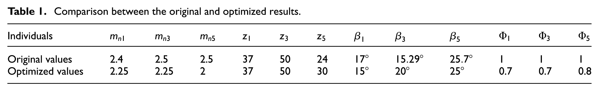
The optimized and original parameter values are listed in Table 1. The transmission system volumes of original and optimized design are
Comparison between the original and optimized results.
The design and check of shafts in transmission system
The structure of the transmission system is optimized, and the transmission shafts should be designed on the basis of optimized structure. According to the working conditions, axial orientation, and circumferential orientation, the structures are designed at first. To guarantee the safety of the structures, the strengths are checked on the basis of diagram of force analysis. The concrete processes are as follows.
The structure design of shaft A
The total power is transmitted by input shaft A, and the preliminary structure design of axis A is designed based on the working conditions. The structure design process is as follows.
Assembly plan on shaft A
Some parts are needed to be assembled on the shaft, such as sealing rings, bearings, sleeves, elastic collars, and gears.
Parts axial orientation
The minimum diameter of the shaft A is defined as below
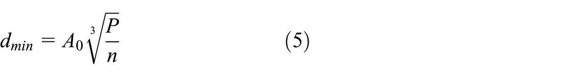
Here, A0 = 97–100.7, P = 22.25 kW, and n = 1440 n/min. So, the minimum diameter dmin = 24.16–25.08 mm.
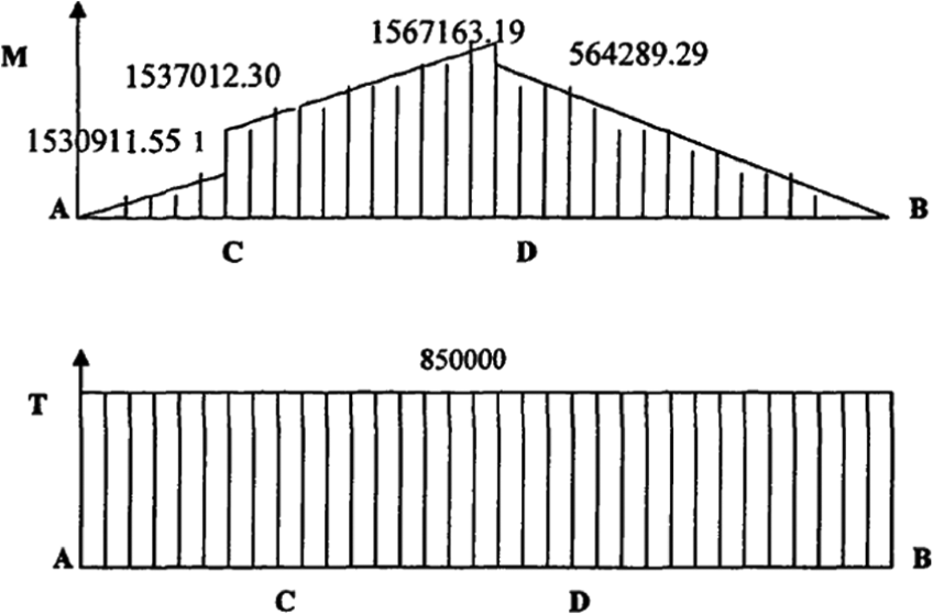
The diameters and lengths are as follows from left to right of each section:
The diameter of the first section is the minimum, and it must match the inter diameter of bearing, so the article chooses d1 = 25 mm and l1 = 110 mm.
The second section needs to be matched with spherical roller bearings, so d2 = 32 mm and l2 = 20 mm.
The third section needs to be matched with tapered roller bearings, so d3 = 40 mm and l3 = 15 mm.
The fourth section needs to be matched with gear, so d4 = 50 mm and l4 = 15 mm.
The fifth section needs to be matched with sealing rings, elastic collars and bearings, so d5 = 40 mm and l5 = 15 mm.
The diameter and length of the last section are d5 = 32 mm and l5 = 20 mm.
According to the analysis and calculation above, the specific structure of shaft A is as shown in Figure 5.

The structure of shaft A.
Parts circumferential orientation
The orientation of clutch and shaft adopts ordinary key of A type, and according to the reference book, the sizes of the key are b × h = 14 × 9 and L = 100 mm.
The chamfer size of the shaft is 1.5 × 45.
Strength check of shaft A
The force analysis diagram is made as shown in Figure 6.

Force analysis diagram.
Here, LAC = 63.5 mm and LCB = 83.5 mm.
The calculation process of gears meshing force is given below.
According to the optimized results in Table 1, the parameters of gear 1 are as follows:


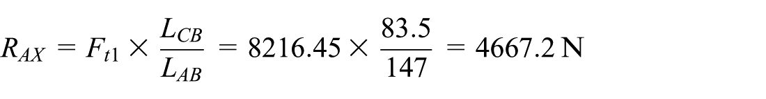
To calculate the supporting force on the horizontal plane, the bending moment diagram is made, as shown in Figure 7, and the calculation process is given as


Bending moment diagram on the horizontal plane.
To calculate the supporting force on the vertical plane, the bending moment diagram is made as shown in Figure 8, and the calculation process is given as below


Bending moment diagram on the vertical plane.
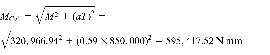
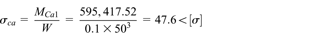
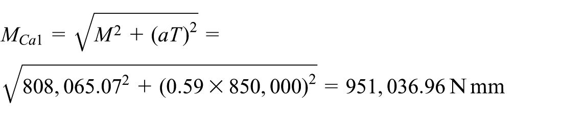
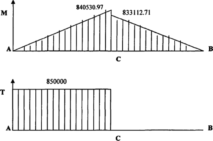
To calculate the general supporting force, the synthetic bending force diagram and torque diagram are made, as shown in Figure 9, and the calculation process is given as below

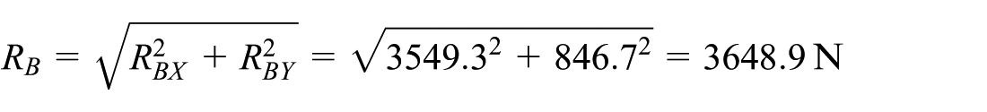


Synthetic bending force diagram and torque diagram of shaft A.
According to the structure of shaft A and the calculation results above, the maximum bending force is on section C, so section C is dangerous and must be checked.
The shafts A, B, C, and D are made from 20CrMnMo, so σB = 1175 MPa, and [σ] = (0.09 − 0.1) σB = 105.75–117.5 MPa, and the calculation process is given below

According to the check results above, shaft A is safe, so the structure design is reasonable.
Design and check of shafts B, C, and D in transmission system
The design and check processes of shafts B, C, and D are similar to shaft A, so the specific processes are simplified as follows.
Design and check of shaft B
The structure of shaft B is shown as Figure 10.

The structure of shaft B.
The synthetic bending force diagram and torque diagram are made, as shown in Figure 11.
Synthetic bending force diagram and torque diagram of shaft B.
According to the structure of shaft B and the calculation results, the maximum bending force is on section D. So, section D is dangerous, and section D must be checked.
The shafts A, B, C, and D are made from 20CrMnMo, so σB = 1175 MPa, and [σ] = (0.09–0.1) σB = 105.75–117.5 MPa


According to the check results above, shaft B is safe, so the structure design is reasonable.
Design and check of shaft C
The structure of shaft C is shown as Figure 12.
The structure of shaft C.
The synthetic bending force diagram and torque diagram are made, as shown in Figure 13.

Synthetic bending force diagram and torque diagram of shaft C.
According to the structure of shaft C and the calculation results, the maximum bending force is on section C, so section C is dangerous, and section C must be checked.
The shafts A, B, C, and D are made from 20CrMnMo, so σB = 1175 MPa, and [σ] = (0.09–0.1) σB = 105.75–117.5 MPa


According to the check results above, shaft C is safe, so the structure design is reasonable.
Design and check of shaft D
The structure of shaft D is shown as Figure 14.

The structure of shaft D.
The synthetic bending force diagram and torque diagram are made, as shown in Figure 15.
Synthetic bending force diagram and torque diagram of shaft D.
According to the structure of shaft D and the calculation results, the maximum bending force is on section C, so section C is dangerous, and section C must be checked.
The shafts A, B, C, and D are made from 20CrMnMo, so σB = 1175 MPa, and [σ] = (0.09–0.1) σB = 105.75–117.5 MPa, and the calculation process is given as below


According to the check results above, shaft D is safe. And after the optimization design above, the whole transmission system model is shown in Figure 16.

The transmission system.
Parameters selection and kinematic and dynamic analyses for twin screw
To check if the twin screw is safe when rotated by the transmission system, the study did the model and analysis by the parameters selection and calculation.
The screw diameter is a basic parameter,
Here, H is the thread height of screw, and the range of H is H = (0.1–0.2)Db. The value of H is bigger, and the production is more efficient, but if H is too big, the strength of the screw will be weaker.
The range of twin-screw helix angle is Ψ = 9°–15°. The study selected Ψ = 10° at first.
The center distance
The screw lead T can be calculated by
Parameter calculation and modeling of twin-screw
Unigraphics (UG) is a very useful software system with the integration of computer-aided design (CAD), computer-aided manufacturing (CAM), and computer-aided engineering (CAE) and has powerful function of modeling, analysis, installation, motion simulation, and so on. 14 Screw model was established at first, and the model was checked to find if interference would happen by the motion simulation. The steps of parameters calculation and modeling with UG are given below:
The outside diameter Db is 70 mm, so cylindrical blank is formed with Db as the diameter.
The pulping flow of the equipment Q = 1.5 m3/h, rotation speed n = 320 r/min, screw head number m = 1, the height of screw thread H = 0.16, Db = 11.2 mm, the center distance CL = Db − H = 59 mm, and the screw lead T = 28 mm, so
The curve parameters of cross section include bevel angle


So

The curve parameters of section.
3. Using the command of Insert Helix, the right-hand helix with helix angle
4. Using the command of Insert Sweep, the three-dimensional (3D) screw model can be established by taking the helix as guide line shaped in Step (3) to sweep, as shown in Figure 18.

Screw model.
Kinematic and dynamic analyses of twin-screw mechanism
After establishing the screw model, the demand of motion in UG was used to do the kinematic and dynamic analyses of twin-screw mechanism. The motion simulation model can be established by giving every part a motion characteristic and a connection. The main steps are given below:
Click the icon Link in the motion simulation zone, and the two screws can be marked as J001 and J002, as shown in Figure 19. Then, click the icon Automatic in the mass properties’ zone to set the property of the connecting rod.
Click the icon Joint to establish the motion pair J001 and J002; the motion driver is set to constant and the velocity is set to 320.
To check whether the interference action will happen when the twin screws are moving, the interference function needs to be set up.

Motion simulation interface.
According to the kinematic and dynamic analyses, interference did not happen, so the design of twin-screw mechanism is safe. The transmission system and the twin-screw mechanism can be installed together and work well based on the optimization design.
Conclusion
In this article, the optimization of multi-objective transmission system design is studied. The article establishes the sum of all volumes as the fitness function, which is the objective function. The 12 parameters of gears are encoded as chromosomes. Under the normal work condition and mechanical performances, the constraints are established. Being different from the traditional method of turning the multi-objective optimization problem into the single-objective problem, the genetic algorithm is introduced in the design. The genetic process simulation is implemented based on those establishments so the optimal parameter values are achieved. From the results, it is obvious that the optimized design is more reasonable, tighter, and installed more easily. Correspondingly, the cost is lower. Based on that optimization results, the transmission shafts and screws are designed and checked, and the results show that the shafts and screws are safe. The study shows that the genetic algorithm is appropriate for multi-objective transmission system optimization design. The number of the objectives is not limited, so the method has wide applicability and practical significance for the more complex design of transmission system in the future.
Footnotes
Academic Editor: Amir Alavi
Declaration of conflicting interests
The author(s) declared no potential conflicts of interest with respect to the research, authorship, and/or publication of this article.
Funding
The author(s) received no financial support for the research, authorship, and/or publication of this article.