
Abstract
The rotor and stator blade lean angle of a hydraulic retarder is one of its main geometrical design parameters. The objective of this study is to clarify the effects of blade lean angle on hydraulic retarder performance. In this article, we employ a computational fluid dynamic approach to numerically investigate the fluid flow of a hydraulic retarder for rotor blade lean angles of 35°, 40°, 43°, and 45° in the direction of rotation, where the stator employs an equivalent angle, and all other geometries are held constant. The numerical results of the braking torque were validated against available experimental results. Analyses of torque performance, flow field, and energy loss are conducted in this study. Additionally, the outer loop oil flow rate is used as another indicator of hydraulic retarder heat exchange performance. The results indicate that with increasing blade lean angle, both the braking torque and oil volume flow rate first increase and then decrease, reflecting an optimal value. The lean angle affects secondary vortex flows and separate flows. Relatively large lean angles may enhance the occurrence of separate flow, whereas relatively small lean angles may cause in the oil inlet region. An optimal blade lean angle achieves a smooth oriented inner flow and a maximum braking torque.
Introduction
Hydraulic retarders are widely used in commercial vehicles and buses as auxiliary brake systems. Hydraulic retarders used in the automotive power transmission systems employ a rotor and stator as the main working components and lubricant oil as the working medium, and the unit is typically mounted on the driveshaft between the transmission and drive axle. The retarder is activated by a pressure control valve that receives signals from electronic control unit (ECU) controller and outputs compressed air of various pressures to control the retarder oil charge and discharge processes. A hydraulic retarder employs a total of five torque shifting positions depending upon the output pressure of the pressure control valve, which includes four fixed torque positions and a speed cruise position. When the retarder is charged with oil, the rotor, which is directly connected to the driveshaft, drives the oil and transfers the kinetic energy of vehicle motion into the kinetic energy of the oil. The kinetic energy of the oil is then converted into heat energy by the stator, and the heat energy is cooled eventually by a heat exchanger. 1 Compared with the conventional friction-based primary brakes, a hydraulic retarder can provide continuous braking over an extended period. As such, a hydraulic retarder can substantially reduce the occurrence of primary brake damage and compromised functionality for vehicles traveling on extended downhill slopes.
Because fluid transport in the blade passage is highly three-dimensional and unsteadily turbulent, with large regions of separated flows and intense secondary flows,2,3 it is quite difficult to design the optimal geometrical dimensions of the rotating components. For many years, steady-state one-dimensional performance models have been employed to analyze fluid couplings and torque converters.4–8 However, the accuracy of the calculations based on these models suffers owing to an excessive number of assumptions that do not agree sufficiently with actual conditions. With the development of high-performance computers, a growing number of researchers have employed computational fluid dynamics (CFD) to investigate fluid flow in blade-wheel rotary machines.9–14
For a rotary machine, the blade geometry is always a crucial performance indicator. At present, various studies have been conducted concerning the effects of blade number, 15 blade wrap angle,16,17 and impeller trimming18–20 on centrifugal pump and hydraulic torque converter performance. Meanwhile, the lean angle is another important parameter affecting blade performance. Based on pressure contour shape, D’Ippolito et al. 21 focused blade lean on the influences of secondary structures and loss distribution in the downstream passage for straight and annular turbine cascade. Harrison 22 investigated the influence of the blade lean angle on loss generation; it was found that blade lean has a marked effect upon blade loading on the distribution of loss generation and on the state of boundary layers on blade suction surface and endwalls. Choi et al. 23 evaluated the effect of blade lean angles on the performance of a regenerative pump with straight rotor blades; they found that pressure head and efficiency depended strongly on the blade lean angles, and head performance decreased as the inclined blades angle increased. Oh et al. 24 employed a CFD approach to study the effects of the blade lean angles on the aerodynamic performance of a high-pressure ratio centrifugal impeller. Here, 15 variations of blade lean angle were investigated, and it was found that a positive lean angle at the impeller, which is good for mitigating the wake region, contributes to a more uniform flow, while a negative lean angle at the impeller exit causes a limited head rise due to a reduced blade loading on the shroud. Similarly, the rotor and stator blade lean angle would also greatly affect the performance of hydraulic retarders. He and Yan 25 studied the hydraulic retarder performance under different vane degree conditions, and velocity, pressure, and kinetic energy distribution of turbulent flows were investigated; the attention was mainly paid to the axial section. Li et al. 26 conducted a hydraulic retarder cascade angle optimization to improve the braking torque coefficient, and the fluid flow was based on a transient multiphase state.
In this article, we employed a CFD approach to numerically investigate the performance and fluid flows in hydraulic retarders with different rotor blade angles strictly leaning in the direction of rotation, where the stator employed an equivalent angle, with all other geometries were held constant. To verify the accuracy of the simulations, the numerical results were compared with obtained experimental data. The torque performance, outer loop oil flow rate, energy loss, static pressure contours, and streamlines on the mid-chord surface with consideration of oil inlet flows were evaluated.
Numerical techniques
Mode geometry
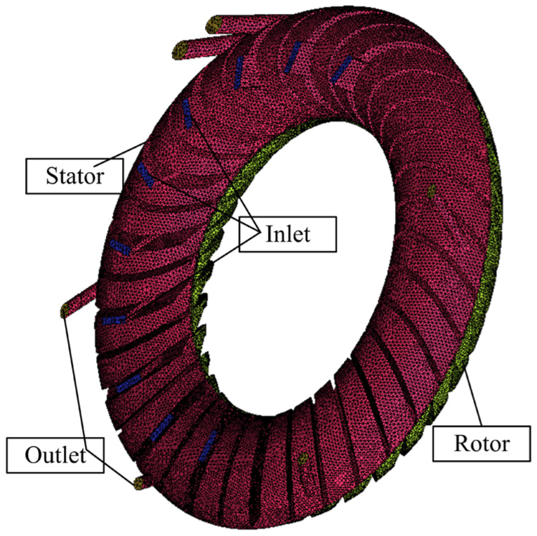
This study employs a VOITH R133-2 hydraulic retarder for both the CFD and experimental analyses, and the main geometrical parameters of which are listed in Table 1. Specifically, oil inlets and oil outlets are all located on the stator. When the rotor blade lean direction is in accordance with the rotation direction, it is denoted here as a front blade lean. A front lean angle contributes to a higher torque performance. As shown in Figure 1, the rotor lean angle is defined as β, and the stator employed in the retarder has an equivalent lean angle to that of the rotor, which enables a greater blade cavity oil capacity. As for the VOITH R133-2 hydraulic retarder, the value for β is 40°. In this study, adjacent values for β of 35°, 43°, and 45° together with 40° are considered to investigate retarder performance.
Main geometrical data for the hydraulic retarder.


Schematic of the rotor and stator of the hydraulic retarder.
Grid-independent analysis and boundary conditions
Due to the inclusion of oil inlets and outlets, the stator has an asymmetrical geometry shape. To balance the convergence time and simulation accuracy, we extracted a full-flow passage model, meshed an unstructured grid, and conducted a grid-independent analysis of the calculated retarder torque. From Figure 2, we can see that the deviation of the calculated rotor torque varies by less than 3% for a cell element number of about 1.77 × 10⁶. Finally, about 1.8 × 10⁶ cells were employed in the simulations. Figure 3 gives a general view of rotor and stator meshes.

Grid-independent analysis with respect to the calculated rotor torque.
A general representation of the rotor and stator meshing.
The oil viscosity is always a crucial factor that greatly influences hydraulic retarder braking performance, and it is very sensitive to the temperature. Jilin University conducted a viscosity–temperature characteristic analysis of hydraulic oil for the retarder and obtained the dynamic viscosity fv (Pa s) as a function of the oil temperature xT (°C) by fitting the experimental data, which was expressed by a quadratic variation as follows 27

As such, the viscosity can be calculated according to the above function based on a known working temperature.
The pressure control valve of the VOITH R133-2 hydraulic retarder, which is a key component for the hydraulic retarder, was tested for the purpose of appropriately setting the numerical simulation boundary conditions. It was found that there were four distinct output air pressure values, which respectively correspond to four fixed torque shifting positions because different air pressures charge different amounts of oil into blade working cavity.
In this study, hydraulic retarder performance for different values of β is investigated with regard to different rotor speeds. All simulations are conducted under steady-state conditions, and the oil viscosity is treated as a constant value. Heat conductivity, heat convection, and heat transfer are ignored. The simulation is performed by ANSYS FLUENT code. The single-phase flow condition is considered in this study, which therefore assigns the pressure inlet as the inlet boundary setting, and the value of the inlet pressure is the maximum air pressure output from the control valve. Outflow is imposed for the outlet. Standard k-epsilon turbulence model with standard wall function is used to model the turbulence, for its low computational requirements and good prediction of pressure-related parameters in pump simulation. 28 The numerical calculation is conducted based on semi-implicit method for pressure linked equations-consistent (SIMPLEC) arithmetic with second-order upwind format for pressure velocity coupling. 29
Simulation validation
To validate the numerical approach, we compared our computed results with results obtained experimentally. A test rig for the VOITH R133-2 hydraulic retarder with a 40° blade lean angle was established at Jilin University. 30 As illustrated in Figure 4, a motor was employed to regulate the rotor rotational speed, compressed air for oil control was supplied by an air pump, and torque was measured by a torque speed tachometer. In the test rig, a motorized pump and an engine radiator together with a fan were utilized to simulate the water cooling system. Because the hydraulic retarders used for both the experimental testing and simulation are of equivalent design, the experimentally obtained braking torque was used to validate the simulation results for β = 40°.
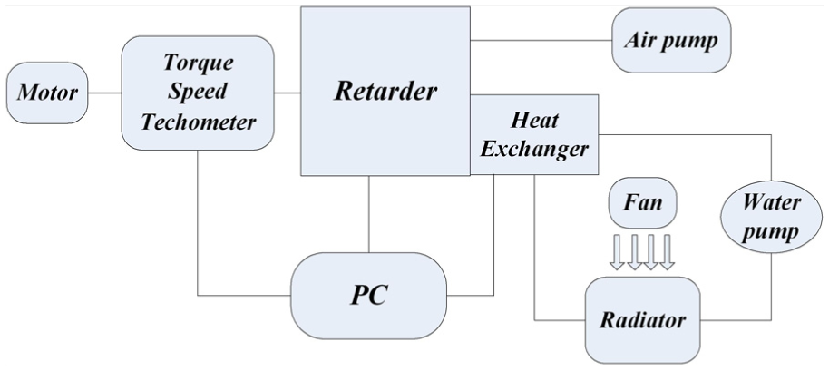
Schematic of the hydraulic retarder test rig employed in the experiment.
As shown in Figure 5, the torque–rotational speed curves obtained from experiment and simulation exhibit an equivalent variation tendency, although the experimental values are generally smaller than the simulation results. This difference is because the simulation employs numerous simplifications such as the removal of geometry fillets and the neglect of temperature variation. Moreover, some leakage losses and mechanical friction losses that occur during the actual experiment are also not considered in the simulation. In addition, the CFD results for β = 40° also fit the performance curve given in the VOITH R133-2 hydraulic retarder product specification very well. 31 Hence, the simulation results are considered reasonably accurate.

Comparison of numerical and experimental results.
Results and discussion
Performance curve analysis
The primary purpose of a hydraulic retarder is to generate torque. Therefore, torque performance is the most important factor. Because the rotor is directly connected to driveshaft, we calculate the torque generated on the rotor as representative of the hydraulic retarder braking torque.
As mentioned earlier, the temperature has a substantial influence on the oil viscosity. Because the hydraulic retarder transfers mechanical energy to heat energy, the oil temperature quickly rises at the beginning of operation, resulting in a dramatic decrease in the viscosity. Moreover, an excessively high temperature can damage the seal components. Both low viscosity and seal damage negatively impact retarder performance. It is therefore essential to evaluate the cooling performance of a hydraulic retarder system. While the simulations treat the oil viscosity as a constant, and heat conductivity, heat convection, and heat transfer are ignored, hydraulic retarder system design involves other aspects that substantially impact the cooling performance, which are considered in the simulations as follows. Figure 6 illustrates the hydraulic retarder oil circulation system. The outer loop oil volume flow rate Q is an independent parameter that is mainly determined by the dimensional structures of the retarder. A suitable value for Q must be considered during the design process to ensure that sufficient heat energy can be transferred from the oil in the working cavity to the heat exchanger, which can then be dissipated by the heat exchanger coolant. Herein, we define the value of Q at the oil inlets as a factor to represent retarder oil exchange capacity.
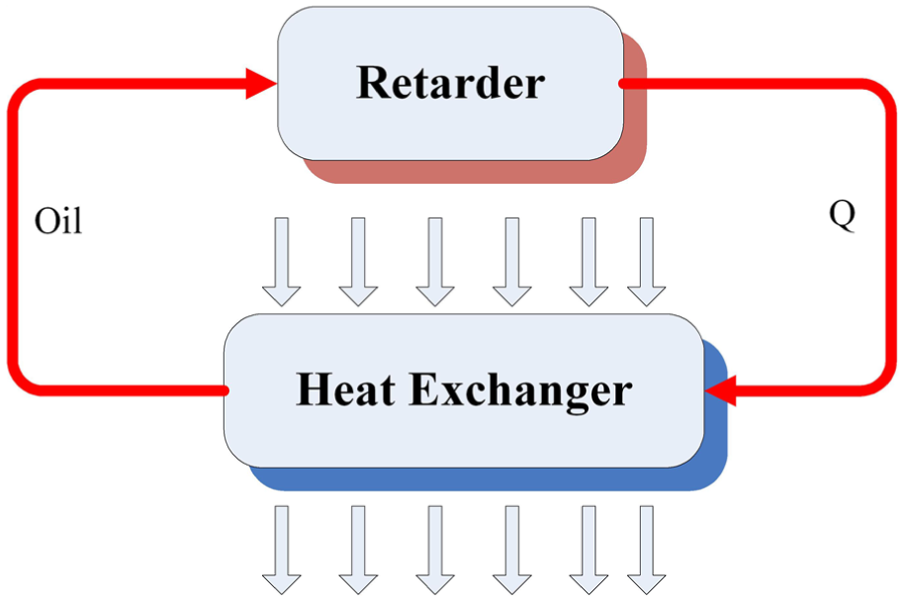
Schematic of hydraulic retarder oil circulation.
The hydraulic retarder performance curves of the braking torque and Q obtained from the numerical simulations for different values of β are given in Figure 7. From dimensional analysis, the braking torque T can be represented by a second-order polynomial function of the rotor rotational speed ω as follows

where λ is the torque coefficient, ρ is the density, g is gravitation acceleration, and D is the outer torus diameter. We observe from Figure 7 that with increasing β, T first increases and then decreases. A similar pattern is observed for Q. We note that the largest values of T and Q are obtained for β = 43°.
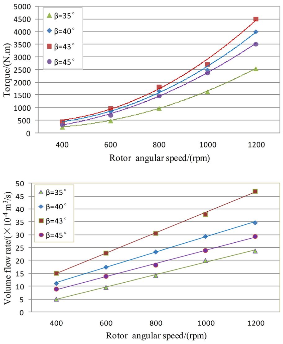
Simulated performance curves of hydraulic retarder for different blade lean angles β.
Flow field analysis
The fluid flow inside the passage is very complex; therefore, this study mainly analyzes conditions on the mid-chord surface with consideration of oil inlets. To enable a fair comparison for different values of β, the following numerical result cases were all computed for ω = 1200 r/min.
Figure 8 illustrates the static pressure distribution for different values of β on mid-chord surface. As shown in the figure, the meridian wall curvature and centrifugal force make a lower pressure level at the interface than at the bottom wall, which gradually changes along the streamwise direction, and as a function of blade loading. In addition, the pressure side has a generally greater pressure than that of suction side. The pressure contours are warped in the circumferential direction due to the blade lean. The rotor and stator exhibit similar pressure distributions. The results demonstrated that the average pressure is greatest for β = 43° for both the rotor and stator, and a high pressure is benefit for the increasing of outer loop oil volume flow rate.

Static pressure contours on the mid-chord surface for different lean angles β.
Streamline analysis can be used to investigate secondary vortex flows in the passage. Figure 9 presents the plotted streamlines for the four different values of β on the mid-chord surface. The color maps in the backgrounds display the velocity contours. It is noted that the pressure on the outer wall surface is greater than the operating air pressure output from the valve. Some extent of reverse flow may be observable for relatively low values of β, like that shown for β = 35°, which negatively impacts oil exchange. Secondary vortex flows are also clearly observed in low velocity regions. This could be explained by the accumulation of low momentum oil in the inlet structure/end-wall corner. Because the hydraulic retarder functions in a manner similar to that of the stall condition of torque converters, owing to the large attack angle, a large area of flow separation is observed on the upper surface of stator blades. The phenomenon is more obvious for small values of β. For β = 40° and 43°, the flow is better oriented regardless of low velocity regions. However, a more intense velocity gradient is observed for β = 43°, making this blade lean angle more suitable.
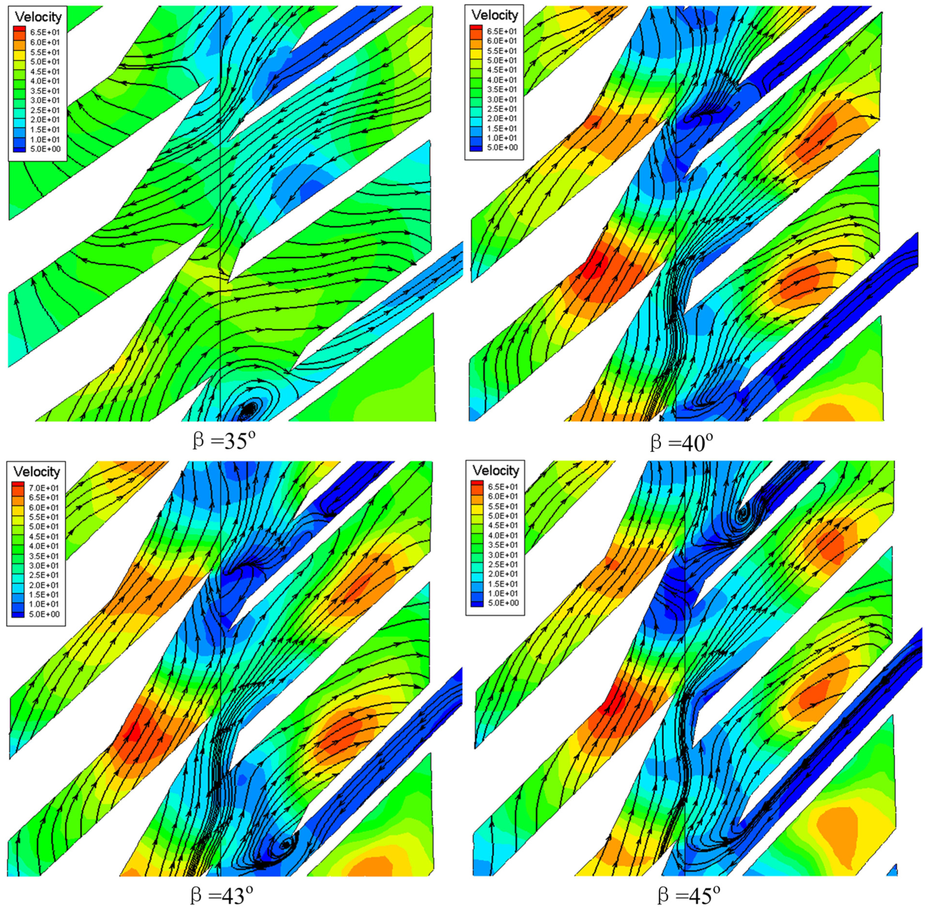
Streamlines and velocity contours on the mid-chord surface for different lean angles β.
Energy loss analysis
Unlike pumps and torque converters, the efficiency of a hydraulic retarder is zero because of the stator. However, from the viewpoint of energy, a hydraulic retarder transfers the power input of the driveshaft into heat energy within the oil. During the energy conversion process, the retarder also suffers some mechanical loss, volume loss, and hydraulic loss. As shown in Figure 10, rotor is connected to the driveshaft with a hollow shaft with internal splines, which must involve some mechanical friction during operation. In addition, because of the different outer torus diameters and the approximately 2-mm axial spacing between rotor and stator, as well as some sealing elements, the oil escapes through the clearances. While this is advantageous for mechanical lubrication, it also results in leakage loss. As such, the oil flowing from the oil inlets does not completely flow out of the oil outlets, and this could be a major source of energy loss. Moreover, secondary vortex and separation flow could also cause hydraulic loss. Finally, because the length of the blade flow passage greatly increases with increasing β, larger blade lean angles increase the hydraulic frictional loss on the wall surface. All these factors influence hydraulic retarder performance.
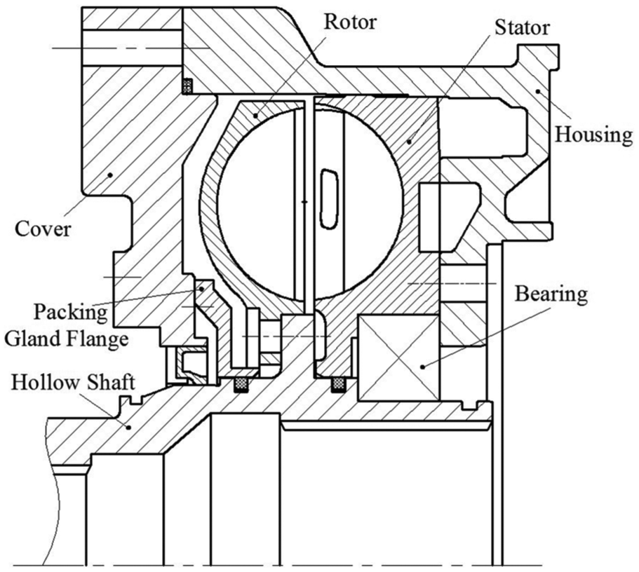
Simplified hydraulic retarder assembly drawing.
Conclusion
This work presented the results of CFD research regarding the performance of a hydraulic retarder with different blade lean angles β of 35°, 40°, 43°, and 45°. Performance curves of braking torque and outer loop oil flow rate with respect to rotor rotational speed were investigated. Besides, based on the static pressures, velocity contours, and streamlines obtained on the mid-chord surface, an oil flow description analysis was conducted. Finally, an energy loss analysis for the hydraulic retarder was discussed based on the assembly structures of hydraulic retarder components. According to the above analysis, some main results can be concluded as follows:
With increasing β, both the braking torque and the outer loop oil flow rate first increased and then decreased, providing maximum values for both parameters at β = 43°, which means a higher braking and heat transfer performance.
Due to the blade lean, the pressure contours are warped in the circumferential direction. The average static pressure was observed to be greatest for β = 43°. Larger values of β were observed to improve the occurrence of separate flow, whereas smaller values of β may cause some extent of reverse flow in the oil inlet region. Secondary vertex flows were observed in the low velocity regions. Analysis of the streamlines indicated that the oil flows are smoother and better oriented for β = 43°, and the velocity gradient is also more intense.
Dimensional differences between rotor, stator, and housing resulted in major leakage loss, although this condition is also beneficial for lubrication. In addition, frictional loss was found to increase with increasing β.
The results of this study indicate that at an optimal blade lean angle of around 43°, the hydraulic retarder would simultaneously achieve the best torque performance, fluid flow, and cooling performance. As such, this study provides a theoretical basis for further optimization work.
Footnotes
Academic Editor: Hongwei Wu
Declaration of conflicting interests
The author(s) declared no potential conflicts of interest with respect to the research, authorship, and/or publication of this article.
Funding
The author(s) received no financial support for the research, authorship, and/or publication of this article.