
Abstract
Aiming at the vehicle power train, system dynamic optimization is profoundly studied based on the system torsional vibration characteristics analysis. First, based on the concentrated mass method, the general torsional vibration model of vehicle power train is established and solved after parameters’ (inertia, stiffness, and damping) matrix and mathematic constraint conditions are acquired. Furthermore, both free vibration and forced vibration characteristics are analyzed. Second, the effects of the coupling stiffness on the dynamics behaviors of power train are thoroughly analyzed. The sensitivity analysis procedure is explored. And sensitivity models of both free and forced vibration feature parameters are deduced. Finally, dynamic optimization theory model and program are constructed based on genetic algorithm. The optimization results indicate that the proposed optimization method could contribute to the sharp attenuation of system torsional vibration.
Keywords
Introduction
Vehicle power train mainly consists of engine and gear transmission. Because of the combustion pressure and variable inertia moment, engine output torque fluctuates periodically with the outer excitation. The gear transmission system has the characteristics of inertia, flexibility, and damping. Therefore, under the engine periodical excitation, the torsional vibration accompanies with the work of vehicle power train. And some special physical phenomena, such as components fatigue fracture, local overheating, and abnormal noise, which will result in the performance degradation of both system reliability and durability, occur occasionally. So it is necessary to explore the more effective approach for the vibration attenuation to improve the vehicle ride comfort and prolong the vehicle active life.
The researches on torsional vibration mainly focused on the modeling simulation, torsional vibration control, analysis of system natural vibration and forced vibration, analysis of parameters’ sensitivity, and so on. The previous studies on the torsional vibration of vehicle power train included the parameters’ identification, the modeling simulation, and the vibration characteristics analysis.1–8 Previous torsional vibration control researches of vehicle powertrain9–18 focused on the way to reduce vibration and noise. Avoiding speed penalty region method and frequency adjusting approach were usually adopted in these studies. It was universal to add different types of elastic coupling and damper to adjust system natural frequency and absorb vibration energy in engineering application. The structure dynamics refinement based on the parameters’ sensitivity analysis has been presented in the torsional vibration studies.19–21 The adoption of several methods of sensitivity analysis, such as derivation method, iterative modal method, expanding rank method, and nonlinear modal synthesis method, provided a theoretical basis for dynamic optimization. Genetic algorithm has a good global searching ability which is suitable for the non-continuous multi-objective optimization.22,23 And this method is adopted in this article.
The torsional vibration characteristics have been exclusively and thoroughly studied according to the aforementioned references. However, there are several problems that need to be solved for the dynamics study of vehicle power train: (1) the precision of structure parameters in the torsional dynamics model and (2) applicable and effective method for vibration attenuation in engineering. In summary, the torsional dynamic characteristics of vehicle power train are precisely acquired based on its concentrated mass model. According to dynamic characteristics’ analysis and parameters’ sensitivity analysis, the dynamic optimization model is constructed. Moreover, the genetic algorithm is used to solve the optimization model. Meanwhile, the proposed strategy of torsional vibration attenuation is validated.
Studied object
The double flow hydraulic-mechanic power train of a certain tracked vehicle is investigated, which consists of V type 12 engine, coupling, front transmission, torque converter, gear box, and so on. Figure 1 shows the simplified model of the power train. The shift exchange can be realized by operating the wet clutch including CH, CL, CR, C1, C2 and C3. The introduction of shifting with corresponding operating elements is shown in Table 1. “•” represents the combination of wet clutch.

Schematic diagram of the studied vehicle power train.
The list of each shift operation method.

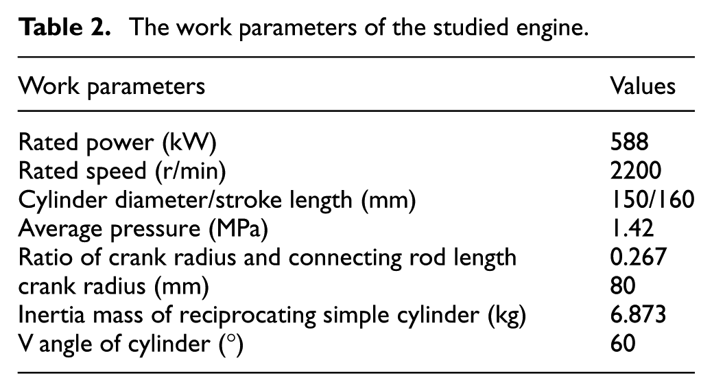
The main work parameters of the adopted engine are shown in Table 2.
The work parameters of the studied engine.
Torsional vibration characteristics
It is found from Figure 1 that the vehicle power train is a continuous and complicated multi-mass-point system. In addition, the distributions of mass, stiffness, and damping are not uniform. System parameters’ (inertia, stiffness, and damping) matrix and mathematic constraint conditions are acquired based on the concentrated mass method. 9 Because the hydraulic torque convertor is locked as a rigid mechanical connection at the fourth, fifth, and sixth shifts, the torsional vibration of vehicle power train is more severe. In addition, the fifth shift is more frequently used in practice, so this work condition is predominantly selected to be studied. It is supposed that the wet clutch driving part is rigidly connected to the driven part when the wet clutch engages completely. And the absolute damping of each concentrated mass point is neglected on the hypothesis. The torsional vibration dynamics model of power train working at the fifth shift is shown in Figure 2.

Torsional vibration dynamics model.
In Figure 2,
After inertia matrix, stiffness matrix, and damping matrix are ascertained, the torsional dynamics model of vehicle power train is established and solved. And then the dynamic characteristics of free vibration and forced vibration are both analyzed.
Free torsional vibration
The essence of natural vibration solution is the eigenvalue extraction from ordinary differential equations. So executive orders “eig” and “inv” in MATLAB can be used to gain system natural frequency and mode shape. When engines work at the rated speed of 2200 r/min, the natural frequency and relative amplitude of power train will be as shown in Tables 3 and 4.
Natural frequency of vehicle power train at different shifts.

Relative amplitude of concentrated mass point at the fifth shift.

As shown in Table 3, the natural characteristics of power train are different from each other at different shifts, which results from the different power flow path and transmission ratio. Furthermore, the difference is more distinct when the shift is not adjacent. However, because of the rigid mechanical connection state of the hydraulic convertor at the fourth, fifth, and sixth shifts, the values of the first- and the second-order natural frequencies are very close at these three shifts. The natural frequency at the hydraulic state is higher than that at the fourth, fifth, and sixth shifts (mechanical state), which demonstrates that the resonance effect is relatively weaker at the hydraulic state.
The relative amplitude of the concentrated mass points at the fifth shift shown in Figure 2 is listed in Table 4. The first five mass points represent each concentrated mass of engine and the sixth mass point is the driving part of coupling. Table 4 shows that the relative amplitudes of engine each mass point are close because of the same dynamic characteristics of each engine cylinder. And the amplitudes of each engine mass point are relatively lower than that of the coupling driving part from the third order to the seventh order as shown in Table 4. Furthermore, the mode shape of engine crankshaft has the node caused by the opposite vibration phase of two adjacent mass points at the seventh order and up. It indicates that engine is relatively safer than transmission system under most working conditions.
Forced torsional vibration
Because of the periodic motivation torque generated by combustion pressure, inertia force, and gravity of reciprocating components, engine output torque, which is the excitation of power train torsional vibration, is pulsating at a constant engine speed. Based on the concentrated mass method, the output torques of studied engine single cylinder under different speeds are obtained as shown in Figure 3. It shows that the output torque changes more unevenly at high speed and the amplitude varies within the same crankshaft angle region.

Torsional torque of single cylinder at different speeds.
According to the harmonic analysis and Fourier transform, the engine output torque is acquired as shown in Figure 4.

Engine output torque: (a) 2000 r/min and (b) 4200 r/min.
Geislinger coupling is used in the studied power train. The stiffness value is 5 × 10⁵ N m/rad according to the calculation formula in the Liu.
9
After the modification of the stiffness and damping matrix, the forced vibration equation with the engine speed of 2200 r/min at the fifth shift is solved. Figure 5 shows the variation of the crankshaft and transmission maximum stress with the engine speed

The maximum stress-engine speed at the fifth shift: (a) the maximum stress of crankshaft and (b) the maximum stress of transmission system.
Figure 5 shows that the maximum stress of crankshaft is distributed between the no. 3 and no. 4 mass point (as shown in Figure 2), and the maximum stress of the transmission is distributed between the no. 11 and no. 12 mass point (as shown in Figure 2). What’s more, the max stress of transmission is lower than that of crankshaft.
Engine combustion pressure and inertia force of reciprocating components are outer excitations. According to the acquired engine excitation, the comprehensive forced vibration angle displacement

where
The angle displacement of the mass point k is
Based on the solution results of forced vibration response, the fluctuant torque of each shaft is obtained regardless of shaft damping. The fluctuant torque of shaft

where
The torsional working stress of the shaft h is

where
From equations (1), (3), and (4), the comprehensive vibration angle displacement of each mass point, the fluctuant torque, and torsional stress of shaft are acquired.
The torsional working stress of the transmission shaft between the no. 11 and no. 12 mass point (shown in Figure 2) and the fluctuant torque of the crankshaft are both obtained as shown in Figure 6. The material of transmission shaft is 40Cr. It shows that the shaft torsional working stress is lower than its allowable stress. And fluctuant torque of crankshaft is below 650 N m.

(a) Working stress and (b) fluctuant torque at the fifth shift.
The effect of coupling stiffness on torsional vibration characteristics
Although the max working stress is below its allowable value, the lifetime of the power train is shorten beyond the allowable range in practice. Therefore, it is essential to optimize the dynamic characteristics of power train. The coupling parameters are convenient to be adjusted in engineering, so the dynamics behaviors of power train under different coupling should be thoroughly analyzed. The effect of coupling stiffness on system natural frequency is analyzed as shown in Figure 7.

The effect of coupling stiffness on system natural frequency. (a) The first-order system natural frequency, (b) The second-order system natural frequency, (c) The third-order system natural frequency, and (d) The fourth-order system natural frequency.
Figure 7 shows that the engine work speed region is so wide that it is impossible to remove the system critical speed away from the speed range of sympathetic vibration only by adjusting the coupling stiffness. Because the first-order mode shape concentrates on the deformation of the engine equivalent mass point, the system natural frequency is not so associated with the coupling stiffness. For the natural frequencies of the third order and greater than the third order, angle vibration displacement corresponding to system critical speeds has to be calculated based on the forced vibration solution. And it is helpful for designing the damper devices to reduce torsional vibration.
Besides the coupling stiffness has the function of frequency shifting for power train, it affects system forced vibration characteristics. According to the formulae (1), (3), and (4), the influences of coupling stiffness on the working stress
The curve of the max torsional working stress: (a) the max working stress of crankshaft and (b) the max working stress of transmission shaft.

The curve of the angle displacement.
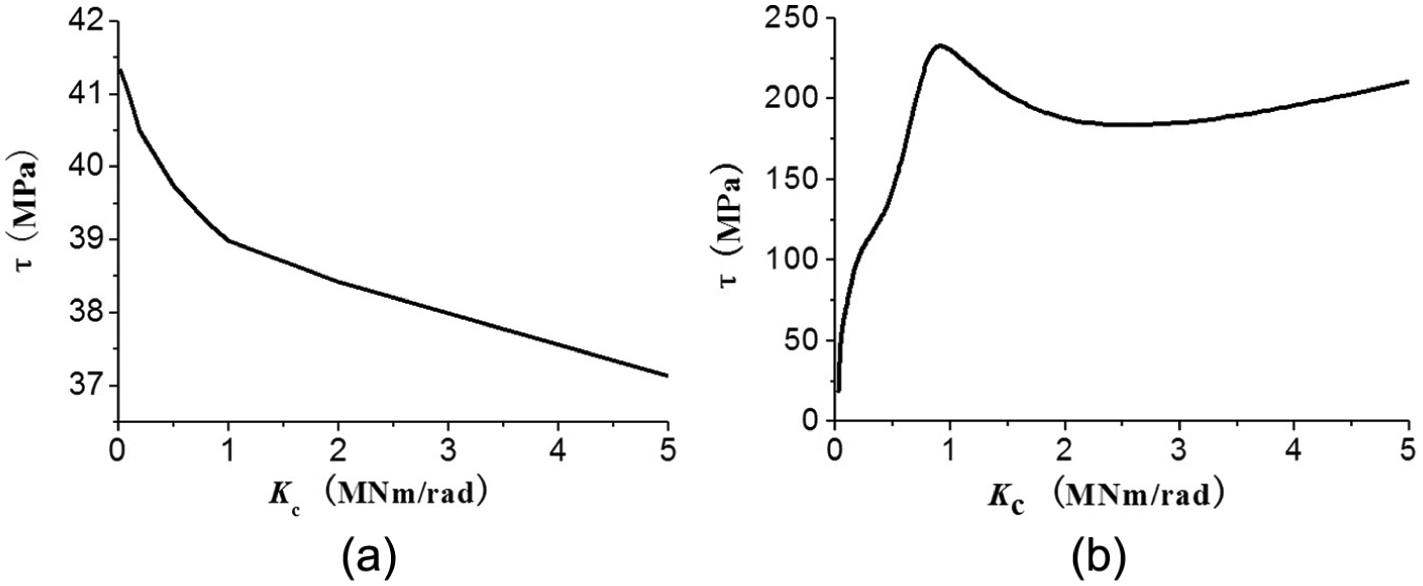
It is known from Figure 8(a) that the torsional working stress of crankshaft is higher while coupling stiffness is low. Figure 8(b) shows that there is the peak stress of gear transmission shaft in the reasonable range of coupling stiffness. And the working stress decreases with the rise of coupling stiffness in the special stiffness region. Moreover, it indicates that the working stress of the transmission shaft is higher than that of the crankshaft from Figure 8. So the gear train is more dangerous.
Figure 9 shows that the angle displacement of crankshaft output point is consistent with that of flywheel. And the angle displacement of coupling driven part is lower than that of coupling driving part. The peak values of all three curves occur when the coupling stiffness is about 1 MN m/rad. Furthermore, the angular displacements reduce significantly as the coupling stiffness increases from about 1 to 2 MN m/rad. It shows that the coupling stiffness has a strong influence on the angular displacement of the system.
According to the results of the above analysis, it is known that the natural vibration parameters (natural frequency) and the forced vibration response (stress, angular displacement) fluctuate strongly with the change of coupling stiffness. The vibration can be reduced effectively by matching the coupling stiffness and the dynamic characteristics of power transmission system.
Dynamic optimization of power train
Sensitivity analysis
Natural frequency and vibration formation of vehicle power train are the function of inertia, stiffness, and transmission ratio. So the sensitivities of system natural frequency and vibration formation, respectively, to the inertia, stiffness, and damping are studied on the basis of the characteristic equation and orthogonal condition. This can help researchers to explore the dynamic optimization parameters of the vehicle power train.
According to Liu et al.,
24
the deduced formula of the second-order sensitivity of natural frequency

The sensitivities of vibration formation
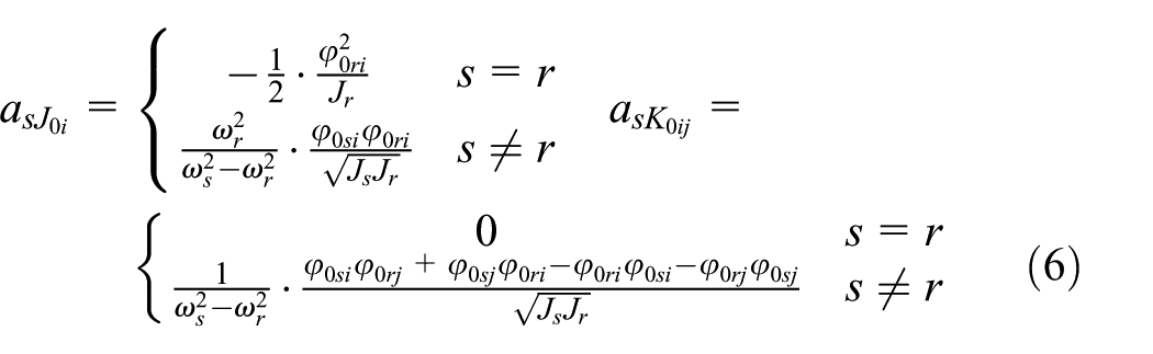

Formulae (5) and (6) show that
The sensitivity of natural frequency to inertia is basically proportional to the square value of natural formation amplitude; the sensitivity of natural frequency to shaft stiffness is also basically proportional to the square value of relative vibration amplitude of mass points on this shaft.
Sensitivities of vibration formation to inertia and stiffness are related to the natural formation amplitude: the most sensitive inertia has the highest vibration amplitude; the most sensitive stiffness belongs to the shaft connecting mass points with the most sensitive inertia.
The sensitive stiffness should be first adjusted to optimize the dynamics behaviors of vehicle power train.
Forced vibration responses should be also analyzed for power train torsional vibration control. A general framework is developed in which the direct differentiating method is adopted to obtain analytical design sensitivity for forced vibration equations. Therefore, how to acquire vibration response sensitivity comes down to the problem of solving the equation. The analysis approach and flow diagram of the forced vibration response sensitivity are shown in Figure 10.

Analysis flowchart of forced vibration response sensitivity.
The vibration working stress, which is one of crucial vibration responses to quantize how the vibration influences system work behaviors, is also thoroughly studied. On the basis of semi-analytic method, the developed sensitivity formulae of working stress to system inertia and stiffness for forced torsional vibration are as follows:
The sensitivity of working stress to inertia

The sensitivity of working stress to stiffness

From formulae (7) and (8), it is known that additional torsional vibration stress is closely related to the coupling stiffness. It indicates that it is feasible to reduce the vibration working stress and ensure the reliability of power train by the optimization design of coupling stiffness.
Optimization design of coupling stiffness
According to the sensitivity analysis, the coupling stiffness is closely related with the vibration working stress. Torsional vibration dynamics behaviors can be optimized by the optimization design of coupling stiffness.
Multi-island genetic algorithm, which can avoid the poor local search ability and premature convergence, is beneficial to acquire the global optimization result. So on the basis of this method, the optimization program is shown in Figure 11.

Optimization flowchart.
Design variable
Based on the sensitivity analysis, dependent parameter which has the obvious effect on system torsional vibration characteristics can just be selected as the appropriate design variable in the state space of power train dynamic optimization. And it must also be controlled directly and conveniently. Coupling stiffness meets these two descriptions. Besides, system torsional vibration decreases as the coupling stiffness drops in the special stiffness range. So the appropriate coupling stiffness is helpful to improve system work performance. Geislinger coupling is used in the studied vehicle. The range of stiffness value is (0.01–0.1) × 106 N m/rad according to the physical experience.
Optimization objective
The ultimate objective of structure dynamics design is to absorb the vibration power. It is demanded that the vibration amplitude and working stress of power train components are within a certain range. Vibration amplitude is closely related to the working stress. So the optimization objective is to minimize the working stress of each transmission shaft.
On the hypothesis of the working stress of shaft bridging, the mass point i and i + 1 is

where
Constraint conditions
To maintain system work normally, it is demanded that vibration angle displacement must be lower than the allowable value, so does the working stress. And the regulation can be described mathematically as follows

The final optimization mathematic model is

PTVA, a developed software in MATLAB to study vehicle power train torsional vibration, is integrated with iSIGHT software to optimize the coupling stiffness. Diagrams of assembly and parameters’ transmission process are shown in Figure 12, which can realize seamless connection of iSIGHT and MATLAB.

Optimization program flow diagram.
The iteration curve of coupling stiffness optimization is shown in Figure 13. Based on the universal optimizer pointer, the coupling stiffness converges from the 64,320 N m/rad to the global optimum 22,367 N m/rad from 64,320 N m/rad after 26 iterations.

Optimization result.
The comparison of vibration amplitude and working stress is shown in Figures 14 and 15. It is known from Figures 14 and 15 that both vibration amplitude and working stress decrease obviously, while the fluctuated trend of optimization curve is consistent with that of the original curve. The maximum working stress decreases by nearly 51.2%. It is known that this optimization approach can reduce the system torsional vibration.
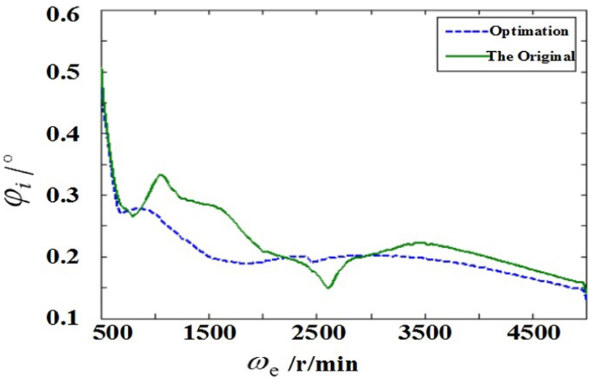
The contrast of coupling vibration amplitude.

The contrast of working stress.
Discussion
The dynamic optimization of vehicle power train was deeply studied based on the analysis of torsional vibration characteristics in this article. The general torsional vibration model of vehicle power train was established and solved. Both free and forced vibration behaviors were deeply analyzed. The effect of coupling stiffness on the system natural mode parameters and forced vibration responses was both explored. Based on the results of parameters’ sensitivity analysis, dynamic optimization model of power train was constructed. And the genetic algorithm was adopted to solve the optimized model. Optimization results (shown in Figures 14 and 15) indicated that the proposed approach could realize the torsional vibration attenuation.
Many previous researches have studied how to reduce the vibration of vehicle power train vibration. D-H Kim et al. 25 presented an advanced shift controller that supervised the shift transients with adaptive compensation. D Richards and DJ Pines 26 used the periodic structures in drivetrains in order to reduce the mesh frequency vibrations and their higher harmonics from being transmitted through structural components in vehicle gearbox. K Inoue et al. 27 proposed a method of stiffener layout design to reduce the vibration and structure-borne noise of gear system. YH Guan et al. 28 developed an experimental active gearbox structure by applying an improved delayed-x LMS control algorithm based on active shaft transverse vibration control concept. These studies focused more on the passive and active reduction in vehicle gearbox vibration. This article proposed the method of coupling stiffness optimization to minimize vibration stress with the combination of PTVA and iSIGHT software. The established optimization model and procedure were universal for the vehicle power train. The results showed that the torsional vibration could be effectively reduced. In contrast with the previous studies, the optimization procedure could be embedded in the PTVA. Therefore, it was more convenient and efficient to acquire and optimize the dynamic characteristics of vehicle power train.
Conclusion
Based on the concentrated mass method, the general torsional vibration model of vehicle power train is established and solved after parameters’ (inertia, stiffness, and damping) matrix and mathematic constraint conditions are acquired. And both free vibration and forced vibration characteristics are analyzed. The main results obtained for the studied power train are as follows: the max stress of transmission is lower than that of crankshaft; the shaft torsional working stress is lower than its allowable stress; fluctuant torque of crankshaft is below 600 N m at the fifth shift with the engine speed of 2200 r/min.
How the coupling stiffness affects the system mode parameters and forced vibration responses is deeply studied based on the dynamic behaviors of both free and forced vibration. The small value of coupling stiffness is beneficial for the vibration decrease in vehicle gear transmission system.
Sensitivity formulae of inertia and stiffness to system natural mode parameters are deduced on the basis of semi-analytic method. The sensitivity of forced torsional vibration amplitude and working stress to system stiffness and inertia is also acquired. These results are the basis of system dynamic optimization.
System dynamic optimization mathematic model is established to minimize the shaft working stress by combining the PTVA and iSIGHT software. Coupling stiffness is selected as the design variable on the basis of sensitivity analysis. Optimization results demonstrate that the global optimum of the coupling stiffness refines system torsional vibration behaviors apparently. It is more convenient and efficient to acquire and optimize the dynamic characteristics of vehicle power train by embedding the optimization procedure in the PTVA.
Footnotes
Academic Editor: Hamid Taghavifar
Declaration of conflicting interests
The author(s) declared no potential conflicts of interest with respect to the research, authorship, and/or publication of this article.
Funding
The author(s) disclosed receipt of the following financial support for the research, authorship, and/or publication of this article: This work was partially supported by the National Natural Science Foundation of China under Grant No. 51505402 and No. 51405410.