
Abstract
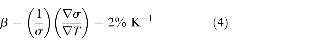
Alternating current electrothermal flow has been extensively used for mixing of fluids in microfluidic systems. This work presents a novel approach to mixing two laminar flow streams in microchannels. The micromixer consists of a pair of asymmetric planar alternating current electrodes disposed along a fluidic channel and a thin film resistive heater below the electrode. Multiphysics (fluid flow, temperature, electrical, and concentration fields) in the micromixer is studied by numerical simulation method. The results indicate that external heating by the thin film resister leads to flow body forces that are proportional to the temperature gradient and chaotic stretching and folding of fluid material lines. Enhancement of mixing is demonstrated by numerical simulation results. Effects of size and location of the thin film resistive heater on mixing efficiency are also investigated.
Introduction
Chip-scale micromixing is essential in many microfluidic devices, which requires rapid mixing of reactants in biochemical processes. 1 However, mixing of fluid streams in microfluidic devices is limited by low value of the mass diffusion coefficient, as well as the low Reynolds number laminar flow and the absence of turbulence to assist mixing in microchannels. To achieve more efficient mixing in a short time and flow length, micromixers based on different actuation methods have been developed, including static, 2 ultrasonic, 3 magnetic, 4 and electrokinetic5–8 micromixers. Among these, electrokinetic micromixers have drawn particular interests due to the ease of operation and improved mixing efficiency.
In general, electrokinetic phenomena involve the motion of liquids or suspended particles under a direct current (DC) or alternating current (AC) electric field. AC electrokinetics has been an attractive approach to flow generation and particle manipulation for several reasons. The most important reason is that it uses low AC voltages (1–30 Vpp), which reduces Faradaic currents and the related generation of bubbles. This is in contrast to DC electrokinetic flows which require hundreds to thousands of volts for actuation. AC electrokinetics can be classified as AC electroosmosis, dielectrophoresis, and alternating current electrothermal (ACET) flow; 9 among which ACET flow has been found particularly useful in the application of fluid mixing in microchannels because ACET flow is the only AC electrokinetic method found viable for actuation of biofluids with high electric conductivities (above 0.1 S/m). 10 In ACET flow, joule heating from the asymmetric AC electrodes induces temperature gradients which produce permittivity and conductivity gradients of the fluid, and net electrothermal body forces are created which result in fluid motion. A number of ACET micromixers11–14 have been proposed for mixing of fluids in microchannels. The ACET mixer in Sin et al.’s 11 work contained annular electrodes, which was capable of generating three-dimensional (3D) vortices, and experimental results demonstrated that ACET mixing can be used to improve the DNA hybridization process and reduce the assay time. Cao et al. 12 proposed an electrothermal vortex enhanced micromixer with electrodes at the two opposite side walls, which utilized ACET flow to enhance mixing efficiency. Such vortex flows have also been shown important in the design and analysis of ultraprecision aerostatic bearings. 13 Ng et al. 14 proposed an ACET micromixer driven by DC-biased AC voltage from a pair of parallel rectangular electrodes along the channel length, which was efficient and suitable for mixing reagents in diverse microfluidic applications.
Recently, Yuan and Wu 10 showed improvement in ACET pumping effects with imposition of external thermal gradients by copper foils which are connected to AC electrodes with hot and cold plates. Wu et al. 15 improved the efficiency of ACET pumping by placing an electrode heater on top of the microchannel. Williams and colleagues16,17 used thin film resistive heaters to enhance electrothermal pumping in microfluidic systems, and their work showed that the heater location and electrode spacing can influence the flow rate of pumping. 17
In this work, we present a novel micromixer based on ACET effects with a thin film resistive heater. The thin film resistive heater is embedded in the glass substrate, separated from the electrodes by an electric insulation. Numerical simulation is performed to demonstrate the benefits of the film resistive heater design to promote mixing of fluids in microchannels, and methodology for the design and analysis of such microfluidic systems is provided.
Description of the micromixer
The sketch of the ACET micromixer with thin film resistive heaters is shown in Figure 1. It consists of a pair of parallel rectangular AC electrodes along the channel length (analogous to the design in Ng et al. 14 ) and a thin film resistive heater, which is embedded in the glass substrate, below one of the AC electrodes with a glass insulation in between. As shown in Figure 1(a), fluid A and fluid B are co-injected into the microchannel at the inlet. Asymmetric AC voltage signals are supplied to the two AC electrodes, and the thin film heater can be independently controlled to create a heat source, as well as a nonuniform temperature field in the microchannel.

Sketch of the micromixer: (a) 3D sketch and (b) cross section.
Numerical model
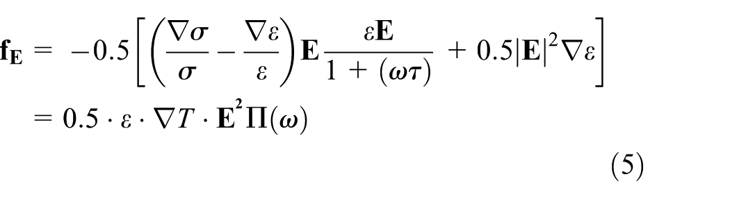
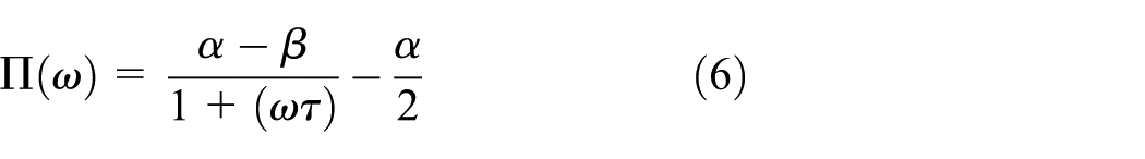
In our multiphysics numerical model, fluid flow in the micromixer is determined by the body force


where
In ACET flows, temperature gradients cause change in the solution conductivity and dielectric constant gradients, resulting in changes in electric field forces exerted on the fluid. The relationships between the dielectric constant and conductivity and temperature are written as 20

where
where


where V is the electric potential.
For equation (8), insulation boundary conditions are prescribed on channel walls, and an asymmetric pair of AC voltages,
The temperature simulation space includes the complete chip (fluid in the channel, glass substrate, glass coverslip, and insulation), and the temperature field is governed by

where T is the temperature and k the thermal conductivity, and convective effects have been ignored. 20 Constant temperature (room temperature) boundary conditions are prescribed on the outermost horizontal boundaries. 16 Thermal insulation boundary conditions are imposed on the side walls of the simulation space. A thin film heater is embedded in the glass substrate, separated from the AC electrodes with a distance of 1 µm. A fixed value of heat flux is prescribed on the surface of the heater to model its heating effect. 16 Fluid temperature at the inlet is assumed to be a constant (room temperature), and an outflow boundary condition of zero normal temperature gradients is imposed at the outlet which is far enough from the AC electrodes.
The transport equation of concentration in the microchannel is written as

where C is the concentration and D is the mass diffusion coefficient. At the inlet, concentration of fluid A is set as 1, and concentration of fluid B is set as 0. The outlet boundary condition of concentration is
The above coupled equations are solved numerically using the finite element software COMSOL Multiphysics. First, equations (1)–(9) are solved simultaneously to obtain the temperature distribution, electric field, and flow field in the microchannel. Then, the flow velocity is substituted into equation (10) to solve for the concentration field. The computational mesh is shown in Figure 2, which consists of 99,215 tetrahedral elements. Grid dependence tests have been performed until successive refinement of the gird results in insignificant changes of the numerical solution. Relative tolerance has been specified to be 0.01 as the convergence criterion.

Computational mesh.
Results and discussions
The micromixer studied in this work consists of a Y-shaped microchannel with a pair of coplanar rectangular electrodes at the bottom of the channel, similar to the electrothermal micromixer in Ng et al.
14
The microchannel that we study is 350 µm long, 20 µm high, and 40 µm wide, which is on a glass substrate (1.0 mm thick) and capped with a glass coverslip (80 µm thick). The two AC electrodes are 120 µm long and 15 µm wide and separated by a distance of 10 µm. Asymmetric AC potentials of 5 V(rms) at a frequency of 106 Hz are applied on the two AC electrodes. The dielectric constant and conductivity of the fluid are
The electric field and temperature field
Distributions of the electric potential and log10E in the channel are plotted in Figures 3 and 4, respectively. Temperature distribution on the same cross section above the AC electrodes in the microchannel with and without the resistive heater is compared in Figure 5, where the color represents the magnitude of temperature and arrows indicate both the magnitudes and directions of temperature gradients. As can be seen from Figure 5, film resistive heating plays a dominant role in the resulting temperature gradient distribution. As shown in Figure 5(a), when there is no external resistive heating, distributions of both temperature and its gradients are symmetric, with the maximum temperature appearing at the bottom of the channel between the AC electrodes due to the strongest electric field (Figure 4) between the asymmetric AC electric electrodes. In contrast, when external resistive heating is present (Figure 5(b)), the maximum temperature appears at the left edge of the right AC electrode, which is a result of the asymmetric heating by the resistive heater. It is also seen in Figure 5(b) that temperature gradient distribution becomes nonsymmetric and significantly increased in the transverse direction (normal to the initial fluid interface) along the vertical center line, which, according to equation (5), is proportional to the fluid body force, and it is this transverse temperature gradient that plays an important role in ACET stretching and folding of fluid interfaces.

Distribution of electric potential (V).
Distribution of log10E.

Distribution of temperature (K) on the channel cross section (a) without the heater and (b) with the heater.
The flow field
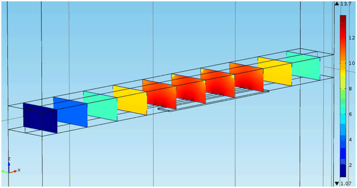
Figure 6 compares the velocity distribution on a cross section (viewed from upstream) above the AC electrodes, with and without the resistive heater, where the color represents velocity magnitude and the arrows indicate both its magnitude and direction. It can be seen from Figure 6 that flow velocities have been increased significantly by external heating, especially in the transverse direction along the vertical center line of the channel. This can be explained by the increased temperature gradient (Figure 5(b)) and the relation between temperature and fluid body force (equation (5)). The maximum velocity (107 µm/s) in Figure 6(b) is also increased by about 919% by external heating, compared with that (10.5 µm/s) in Figure 6(a). The transverse motion of the fluid results in stretching and folding of material lines, and mixing is enhanced by exponentially increased material contact area and molecular diffusion across the interfaces.

Velocity (m/s) distribution on the cross section (a) without the heater and (b) with the heater.
The concentration field
Figure 7 plots concentration distribution on different cross sections with and without the resistive heater. It is clearly seen that very limited mixing by molecular diffusion occurs near the vertical center line throughout the channel when there is no resistive heater (Figure 7(a)). However, rapid mixing can be seen when the flow passes the electrodes in the presence of the heater (Figure 7(b)), which is due to the chaotic ACET flow field in Figure 6(b).
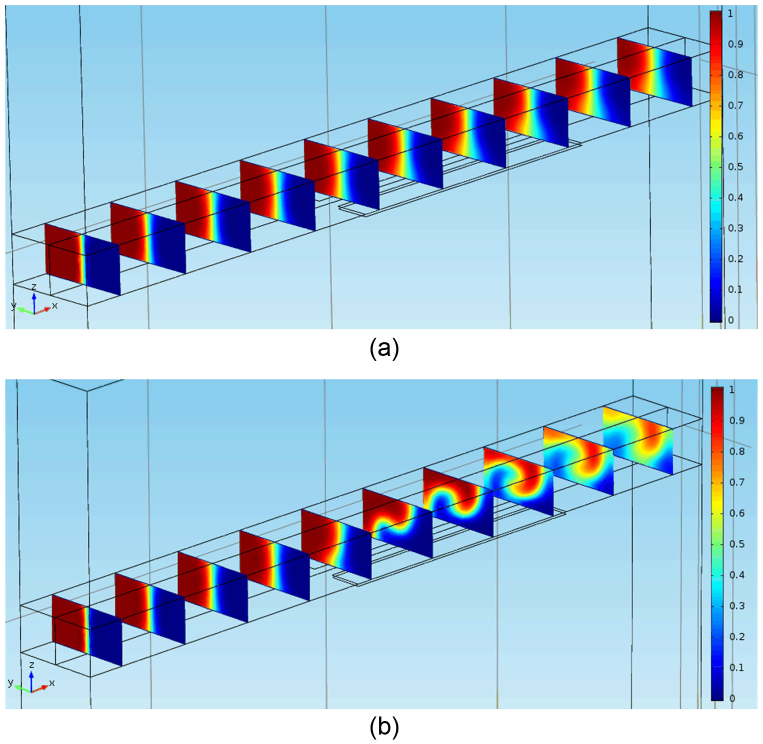
Concentration distribution on different cross sections (a) without the heater and (b) with the heater.
To quantify the effects of mixing, a mixing efficiency defined as in Erickson and Li 21 is used

where
Validation
A computational model with the same geometric and physical parameters as an ACET micromixer in Ng et al.
14
is first developed. Although this does not have external heating, experimental results in Ng et al.
14
are used to validate our computational model and numerical results. The 3D computational model is 1350 µm long, 100 µm wide, and 44 µm high. The coplanar AC electrodes are 500 µm long and 40 µm wide and separated by a distance of 20 µm at the bottom of the channel. Asymmetric AC potentials of 15 Vpp at the frequency of 500 kHz are applied on the two AC electrodes. The fluid conductivity is 0.5 S/m, and the fluid diffusion coefficient is
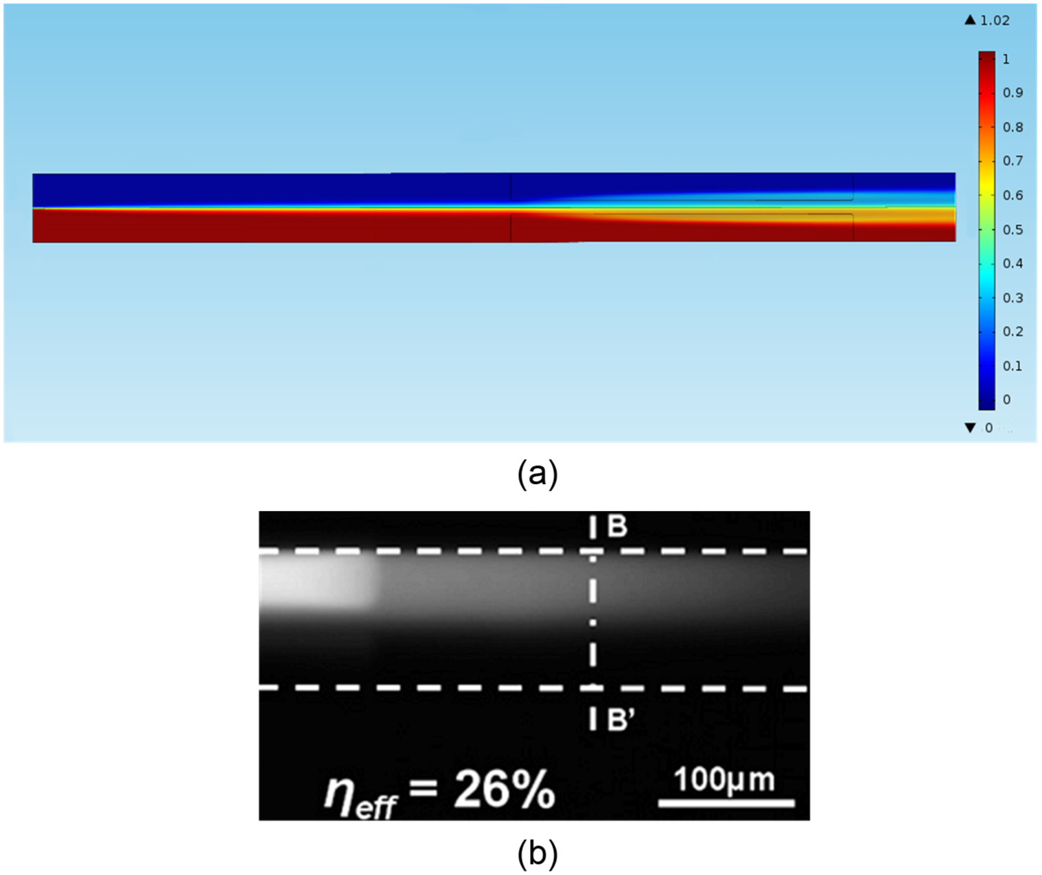
Comparison of our simulation results with experimental results: (a) numerical concentration distribution (top view) and (b) experimental image of the intensity profile from Ng et al. 14
Parametric effects
Effects of resistive heating strength
The heat flux on the resistive heater surface is reduced to
Mixing efficiencies with different heat flux values on the heater.

Effects of resistive heater size
Length of the resistive heater is first varied (symmetrically in both directions) to investigate its effects, and the results are plotted in Figure 9, which shows that the mixing efficiency increases with increasing heater size. This is due to the increased longitudinal length of fluids with temperature gradients above the heaters. However, the mixing efficiency reaches an asymptotic value when the heater is slightly (about 60 µm) longer than the AC electrodes because of the exponentially decaying electric field away from the AC electrodes.

Variation of the mixing efficiency with length of the resistive heater.
Width of the resistive heater is also varied, with its length being equal to that of the AC electrode, to investigate its effects on the mixing efficiency, and the results are listed in Table 2. From Table 2, it can be concluded that optimal mixing occurs when the resistive heater occupies half width of the channel. This is due to the strongest temperature gradients at the transverse center plane (fluid interface) when the heater has one-half width of the channel (Figure 10(c)).
Mixing efficiencies with different heater widths.
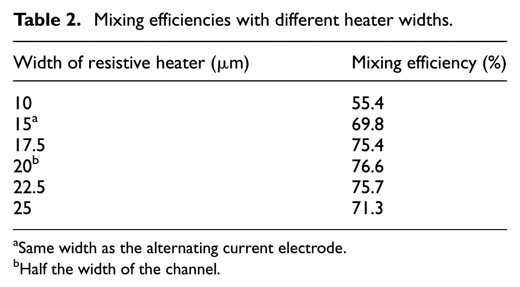
Same width as the alternating current electrode.
Half the width of the channel.
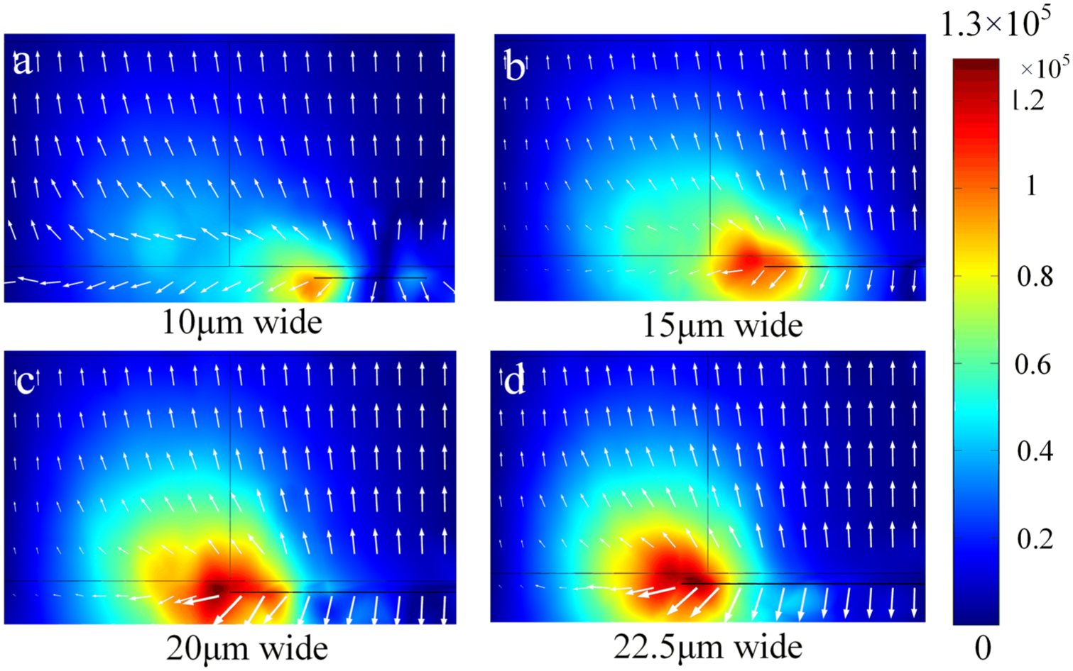
Temperature gradients (K/m) on a cross section above the AC electrodes with different resistive heater widths:(a) 10 μm wide; (b) 15 μm wide; (c) 20 μm wide and (d) 22.5 μm wide.
Effects of resistive heater location
The resistive heater location in section “Results and discussions” is used as the benchmark and then varied to investigate its effects on the mixing efficiency. First, the heater is moved in the longitudinal direction, and the results are plotted in Figure 11, where positive displacement means moving the heater downstream and negative displacement means moving the heater upstream. From Figure 11, one can see that the mixing efficiency decreases when the heater is moved downstream because of the decreasing overlapping area of temperature gradients and AC electric fields, where the ACET body force helps to improve fluid mixing. When the heater is moved slightly upstream, temperature gradients prior to the leading edge of the AC electrodes help to improve mixing where the AC electric field is still nonnegligible. While at the downstream side above the heater, fluid temperature and concentration have become more uniform after external heating and ACET mixing, and contribution of the AC electric field to ACET mixing is much less significant. When the heater is moved further upstream, most of the cross sections above the heater prior to the AC electrode leading edge experience vanishing AC electric fields, and the mixing efficiency decreases. These explain why the curve in Figure 11 first goes up, reaches a maximum, and then goes down. The optimal mixing efficiency is obtained when the heater is moved slightly upstream (about 7.5 µm).

Variation of the mixing efficiency with different heater displacements in the longitudinal direction.
Then, the resistive heater is moved in the transverse direction toward the center of the channel, and the results are listed in Table 3. As can be seen from Table 3, transverse location of the resistive heater has negligible effects on the mixing efficiency until the heater edge reaches the center line of the channel, in which case the mixing efficiency starts to decrease. This is more clearly seen from Figure 12, in which temperature gradients normal to the fluid interface at the center start to decrease when the heater is moved past the center line.
Mixing efficiencies with different heater displacements in the transverse direction.

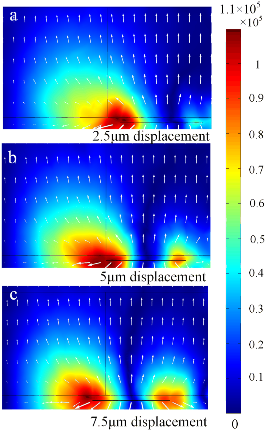
Temperature gradients (K/m) with different resistive heater locations in the transverse direction: (a) 2.5 µm displacement; (b) 5 µm displacement and (c) 7.5 µm displacement.
The distance between the resistive heater and the AC electrode is also varied to investigate its effects, and the results are listed in Table 4. From Table 4, it can be seen that the mixing efficiency decreases with increasing distance between the resistive heater and the AC electrode.
Mixing efficiencies with different distances between the resistive heaters and AC electrodes.

AC: alternating current.
Comparison of mixing efficiencies
From the above results, it can be calculated that optimal mixing for the above micromixer with a thin film resistive heater can be achieved when the heater is below one of the AC electrodes, 60 µm longer than the AC electrode with half the width of the channel, and moved 7.5 µm upstream. When the heat flux on the heater surface is
Conclusion
In this article, a novel ACET micromixer with an external thin film resistive heater has been proposed. To the best of our knowledge, this is the first micromixer that uses thin film resistive heaters to enhance ACET mixing of fluids. After validation of our multiphysics numerical model of the micromixer by quantitative comparison with experimental results in the literature, our numerical results show that rapid mixing of fluids in the microchannel can be achieved by this novel ACET micromixer with thin film resistive heaters. Our numerical results also indicate that optimal mixing can be achieved by a thin film rectangular resistive heater below one of the AC electrodes, slightly (about 60 µm) longer than the AC electrode with half the width of the channel, and moved slightly upstream (about 7.5 µm). Mixing efficiency of the micromixer also increases with increasing heating strength and decreasing distance between the heater and the AC electrode. However, the minimal distance between the heater and the AC electrode is usually limited by fabrication techniques.
Footnotes
Academic Editor: Mark J Jackson
Declaration of conflicting interests
The author(s) declared no potential conflicts of interest with respect to the research, authorship, and/or publication of this article.
Funding
The author(s) disclosed receipt of the following financial support for the research, authorship, and/or publication of this article: This work was supported by the National Natural Science Foundation of China (numbers 11172111, 11572139, 51175196, 51435006, and 51235005).