
Abstract
To solve the problem that gravity deformation curve of large-span cast-iron beam analyzed by finite element method simulation is inaccurate due to material imperfection, a discretization calculation considering the inhomogeneity of the material based on finite difference method is proposed. Supposing the flexural rigidity of the beam is different along the length, the continuous beam is discretized into segments based on finite difference method, and equivalent flexural rigidity is presented to characterize the inhomogeneity of the material. Correction model of bending deformation is constructed to revise the results of finite element method simulation applying equivalent flexural rigidity that could be obtained by combining the discretization model and deformation data acquired in a simple self-load experiment in which the beam is simply supported without any assembly process. Finally, flowchart of application is presented, and the approach is illustrated through an example from real case. The experimental results show that the computational accuracy is improved from 73.14% to 88.33%, compared with just finite element method simulation.
Keywords
Introduction
Large and accurate parts are desired for high-growth sectors such as rail road, aeronautics, and shipping. One obvious solution to machine very large parts is to build large machine tools. 1 The accuracy of heavy-duty machine tools is a critical factor that directly affects the quality of large-scale products. Consequently, researches on errors induced by static and dynamic problems in heavy-duty machine tools have been carried out. Static errors of heavy-duty machine tools were detected and compensated by laser instruments to improve the accuracy of large computer numerical control (CNC) machine tools.2,3 Urbikain et al. 4 established models in heavy-duty turning operations for a large horizontal lathe to identify the machine design features limiting lathe productivity, as well as the threshold values for choosing good cutting parameters. The accuracy of heavy-duty machine tools is primarily affected by the geometric errors caused by imperfections, misalignments, wear of the linkages, and elements of the machine tool structure by static load-induced errors. 5 The object loading behavior, object weight, and unbalanced unforeseen forces in machine elements determine the magnitude of load-induced errors. Wang et al. 6 presented an approach for compliance analysis of a three-surface plasmon resonance (SPR) parallel mechanism forming the main body of a 5-degree-of-freedom (DOF) hybrid manipulator which took gravity and joint compliances into account. Wu et al. 7 derived the formulas of compensation forces and torques according to the principle of torque balance with the consideration of gravity effect to compensate the deformation error of heavy-duty CNC floor-type boring–milling machine. Ni and colleagues8,9 developed a comprehensive error compensation system for a turning center taking into account the cutting force–induced error which is not negligible in some conditions. Raksiri and Parnichkun 10 utilized combined back-propagation neural network to establish the compensation model of geometric error and cutting force–induced error for a three-axis milling machine. A multilevel machining error compensation approach focused on force-induced errors, which took into account the deflection of the part in different points of the tool path, was introduced in machining of thin-wall structures. 11
Gravity is one of the typical static loads that cause errors in machine tools and is of great importance especially for large heavy-duty type. 12 However, compared with other load-induced error, it is less analyzed. The deformation of components resulted from gravity cannot be ignored due to their huge weight, size, and span. Large-span beam, whose length is generally >10 m, is a typical form of structure for heavy-duty machine tools. As the core component, the parallelism of surface of the table with respect to displacement of the tool post, which is defined as G5 verification in ISO 3655:1986, 13 is one of the most essential accuracies for the quality of heavy-duty vertical lathe. Generally, it is effective to improve the accuracy of G5 verification by processing the camber curve to compensate the gravity-induced error. However, the beam has to be repaired and assembled repeatedly with high cost and waste of time if the gravity deformation of the beam cannot be calculated accurately. Quite a few researches have been conducted to improve the accuracy. Guo et al. obtained the camber curve of a large-span beam by finite element method (FEM) simulation. The experiment indicated that the error of FEM simulation is 7%–16%. 14 But such a method for the specific object did not analyze the reason resulting in the error and is not likely to be universal. Considering load-induced errors aroused by internal masses of machine tool components and external cutting forces as the main contributors affecting machining accuracy, Cheng et al. 15 proposed a method for optimization of the guide rail camber curve on beam by particle swarm optimization according to the load-induced errors identified by an identification model of large-span beam. The camber curve was obtained by the optimization that minimized the load-induced error in FEM simulation, but it did not take the material property into account. Yiyong et al. 16 analyzed the deformation of a gantry-type beam on the basis of the simplified mechanical model by FEM, and the accuracy of the model was indicated by the simulation results. The research just focused on the deformation of component affected by normal force.
The components of heavy-duty machine tools are generally made of cast iron due to its stability and low cost. However, the imperfections such as sand inclusion, gas hole, inhomogeneity of material, and designed size error inevitably exist. These imperfections influence material property because of the uncontrollability of foundry technique, which is inferred as one of the reasons resulting in the inaccurate of gravity deformation curve calculation by FEM simulation due to constant input parameters of the material. Theoretically, to make the result of FEM simulation accurate, the actual flexural rigidity of all the segments is indispensable due to the inhomogeneity of the material. However, it is hard to be measured. Even if it could be measured, it is also difficult to segment the beam model and input the actual flexural rigidity into the corresponding segments by FEM simulation. To improve the prediction accuracy of gravity deformation curve of long-span beam for heavy-duty vertical lathe, with consideration of the inhomogeneity of the material, a calculation based on finite difference method (FDM) is proposed. A term “equivalent flexural rigidity” is proposed to characterize the inhomogeneity of the material. And the “equivalent flexural rigidity” in different segments of the beam could be acquired through a simple self-load experiment in which the beam is just required to be placed in simple status without any assembly process. Then, the gravity deformation curve solved in FEM simulation with constant material parameters is corrected according to the proposed correction model.
Mathematical models of deformation correction and equivalent flexural rigidity
When the tool rest moves along the guide rail, due to the weight of the tool rest and the beam itself, the deformation of bending exists. Therefore, to build the mathematical model of deformation correction, models of bending deformation should be established.
Model of bending deformation caused by gravity
The large-span beam of a heavy-duty vertical lathe is shown in Figure 1. The reference coordinate frame of the beam is built in the following.

Large-span beam of heavy-duty vertical lathe (top view).
Considering the midpoint O of the beam in the bearing surface as the origin of coordinate, a reference coordinate frame is built with the positive direction of X-axis along the guide rail. Y-axis is perpendicular to X-axis in the plane in which the bearing surface of the beam is. Z-axis conforms to the right-hand rule.
According to the assembly condition of the beam, the theory of material mechanics is utilized to simplify the calculation model as a mechanical model of simply supported beam. Self-weight load is regarded as uniformly distributed loads exerted on the beam with representation of qi (i = I, II). The simplified mechanical model is shown in Figure 2, where L, L1, L2, and a are, respectively, half the length between the supports A and B, the length of the beam exerted by qI in both ends, the length of the middle beam exerted by qII, and the length of the overhanging parts of the beam.

Simply supported beam model under gravity load (front view).
As the span–depth ratio of the beam is >5 (with the span of 7250 mm and the height of 1350 mm), the model of bending of the beam under gravity load could be established utilizing the differential equation of flexure for the straight beam as equation (1)

where x, Z(x), M(x), E, and I(x), respectively, represent the position of the beam, the deformation curve of the beam affected by gravity, the bending moment in x position, the elasticity modulus, and the moment of inertia of the section in x position.
FDM-based discretization model of bending deformation
Since deformation of bending occurs during the self-weight load experiment (section “Self-weight load experiment”), it is necessary to discretize the model of bending deformation of constant material parameters considering the inhomogeneity of material (equation (1)). Therefore, supposing the material parameters are various in all segments of the beam, the discretization model of deformation caused by gravity based on FDM for the beam could be established in the following.
Dividing the beam into n segments, the coordinate of the ith segment (Figure 1) could be expressed by equation (2) with x0 representing the coordinate of the initial segment from the left side

where h = 2L/n with h representing the step length.
According to the equation of second-order difference and the differential equation of flexure shown in equation (1), the discretization model of deformation caused by gravity considering the inhomogeneity of material is established by equation (3)

where zi (i = 0–n − 1), Mi, and (EI) i , respectively, represent the deviation to Z-axis, the bending moment, and the flexural rigidity of the ith segment.
Calculation of the equivalent flexural rigidity
The equivalent flexural rigidity is applied to correct the result of FEM simulation. As the parameter (EI) i is involved in equation (3), combining the acquired deformation data in the self-weight load experiment and the discretization model of bending deformation caused by gravity, the equivalent flexural rigidity of all the discretizing segments could be calculated to characterize the property of actual material.
Based on the above, rewrite equation (3), and the calculation of equivalent flexural rigidity is shown in equation (4)
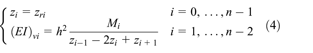
where zri (i = 0–n−1) and (EI) vi are, respectively, the Z directional deformation under self-weight load in the experiment and the equivalent flexural rigidity. After acquiring the equivalent flexural rigidity, the gravity deformation curve could be calculated applying the calculation presented above.
FDM-based correction model of the result of FEM simulation
For the bending deformation of the beam, the relationship between Z directional deformation and flexural rigidity has been presented by equation (3).
As the constant value of material parameters inputted in FEM pre-processing cannot characterize the inhomogeneity of the material, the result of FEM simulation should be corrected by the equivalent flexural rigidity to calculate the accurate curve of gravity deformation. As shown in equation (5), the second-order difference equation is utilized to deal with the deformation solved by FEM simulation based on FDM (section “FEM simulation of the beam under gravity load”)

where
According to equation (3), the relationship between the corrected Z directional deformation

Combining equations (5) and (6), the correction model of bending deformation is presented by equation (7)

where the ratio between (EI) input and (EI) vi of the ith segment is defined as the correction factor ki, as is shown by equation (8)

To make the boundary condition approaching the actual assembly condition of the beam stated in section “FEM simulation of the beam under gravity load,” it is considered that the deformation trends to be calculated near the supports are as same as the ones solved in FEM simulation. Therefore, the additional boundary condition of equation (8) is given as: k1 = kn−2 = 1.
FEM simulation of the beam under gravity load
FEM simulation of deformation caused by gravity of the beam should be conducted so that the gravity deformation curve could be calculated applying the correction model of FEM simulation based on equivalent flexural rigidity and FDM. In this section, ANSYS Workbench is applied to conduct FEM simulation.
Pre-processing in FEM simulation
The heavy-duty vertical lathe consists of beam, columns, tool rest, and so on. To obtain the deformation curve of FEM simulation, the material property parameters are required involving elasticity modulus E, Poisson’s ratio ν, and density ρ. The value of material property is shown in Table 1.
Material property parameters of components.

The main column stands on the right side with the auxiliary column on the left side. When assembling the beam, wedges are used to eliminate the gaps between main column and beam. With the effect of the wedges and the clamping device of oil cylinders, the DOFs are completely limited except the one of translation along the Z-axis. The assembly condition of the auxiliary column is as same as that of the main column except a5-to 10-mm gap between auxiliary column and beam, which results in the limitation of DOFs of translation along the Y-axis and rotation with respect to the X-axis and Z-axis. The gravity load of the beam is mainly supported by the screws, which leads to the limitation of DOF of translation along the Z-axis in the position of the screw.
According to the analyzed assembly condition, the corresponding supports including displacement of 0 mm and cylindrical support are set up in ANSYS Workbench to simulate the actual situation of assembling. At the same time, the loading is defined by Standard Earth Gravity.
Result of FEM simulation
The Z directional deformation curve of the tool nose affected by the gravity of beam and the tool rest is regarded as the difference between the Z directional deviation curve and the original curve which is an ideal straight line with no deviations in FEM simulation. The Z directional deformation of the tool nose is solved every 460 mm along the beam, and the curve is plotted (Figure 3).

Z directional deformation curve of the tool nose affected by the gravity.
Experiments and results
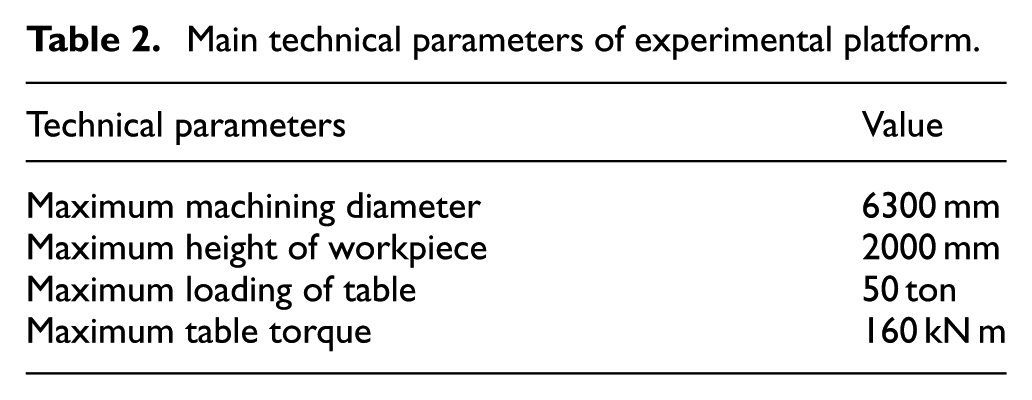
The heavy-duty vertical lathe applied as experimental platform which is established by Qiqihar Heavy CNC Equipment Corp. Ltd is shown in Figure 4, and the main technical parameters of the experimental platform are listed in Table 2.

Experimental platform of heavy-duty vertical lathe.
Main technical parameters of experimental platform.
Flow diagram of calculation
First, a self-weight load experiment of the beam under the condition close to the actual assembly is designed to acquire the deformation data of the beam affected by the self-weight load. Second, the equivalent flexural rigidity of all the discretizing segments is calculated according to the discretization model of deformation caused by gravity based on FDM. Third, FEM simulation of deformation caused by gravity of the beam is implemented. Then, the calculated equivalent flexural rigidity is applied to correct the resulting curves of FEM simulation based on FDM so that the accurate gravity deformation curve of the beam could be plotted. Finally, G5 verification is performed to verify the calculation. The flow diagram of the calculation of gravity deformation of the beam based on FDM is presented in Figure 5.

Flow diagram of the calculation of gravity deformation of the beam based on FDM.
Self-weight load experiment
To acquire the equivalent flexural rigidity, it is necessary to acquire the deformation data of the beam through the self-weight load experiment. The self-weight experiment is convenient to be conducted without any assembly process, and the data are easily obtained by placing the beam in simple status, as is shown in Figure 6.

Self-weight load experiment: (a) different placement status of the beam in self-weight load experiment and (b) Z directional deviation measuring at sideward placement.
The deformation data of the beam affected by the self-weight load is captured by measuring the Z directional deviation which is also regarded as the straightness error of the bearing surface at sideward placement and flatwise placement.
At the first step, according to the experiential camber curve of the beam, the initial surface of guide rail is machined by a milling machine at flatwise placement (Figure 6(a)) into curved shape to balance the effect of gravity. After machining, the deviation to Z-axis is measured. Second, the beam is put at sideward placement, and sizing blocks are used to support the beam at the same fitting position as the columns do. The deviation to Z-axis will not be measured until the deviation caused by gravity remains steady (Figure 6(b)).
The Z directional deviation is captured by autocollimator. The measured deviations to Z-axis are illustrated in Figure 7. From Figure 7, an asymmetrical effect of measuring deviations is found. The imperfections of material or actual size errors leading to the inconsistent deformation of the beam, the asymmetrical positions of the sizing blocks, and the measuring environment could be assumed to explain the asymmetrical effect. In this study, the former is considered as the dominant factor. This is the reason why the real deformation affected by the self-weight load is necessary. The deformation data of the beam affected by the self-weight load are obtained by the difference between the deviation at sideward placement and flatwise placement.
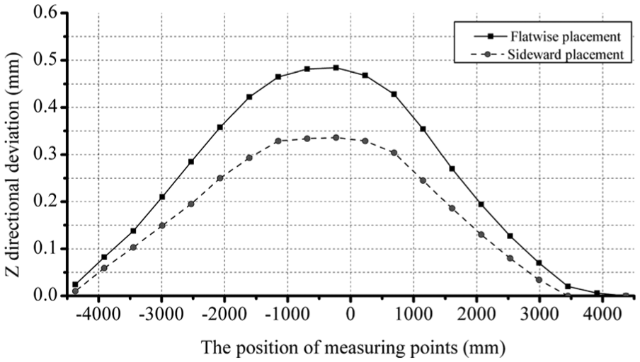
Measuring deviation to Z-axis at different placements in self-weight load experiment.
Calculation result of equivalent flexural rigidity
After the deformation data of the beam affected by the self-weight load are captured in the self-weight load experiment, equivalent flexural rigidity could be calculated by applying the calculation introduced in section “Calculation of the equivalent flexural rigidity.” The result of the calculation of equivalent flexural rigidity is illustrated in Table 3.
Result of the calculation of equivalent flexural rigidity.

G5 verification experiment and the result of the calculation of gravity deformation
To verify the validity of the calculation proposed, the actual deformation of the beam is required. It could be obtained by the G5 verification experiment.
The G5 verification experiment is conducted under constant temperature so as to eliminate the influence of the ambient temperature. According to ISO 3655:1986, the vertical lathe could be considered to attain thermal equilibrium after running for a period of time and then the dial indicator is used to measure the accuracy of G5 verification, as shown in Figure 8. The experiment result curve is plotted (Figure 9).

G5 verification experiment using dial indicator.

Result curve of G5 verification.
As the same acquirement of gravity deformation curves in FEM simulation, the actual deformation of the beam is also regarded as the difference between the G5 verification curve and the deviation to Z-axis at flatwise placement in the corresponding positions. The gravity deformation curve is calculated by applying the calculation based on FDM introduced in section “Mathematical models of deformation correction and equivalent flexural rigidity,” and the deformation curves generated by FEM simulation and correction model are compared in Figure 10.

Result of comparison of gravity deformation curves of different methods.
As shown in Figure 10, the trend of the FDM-based calculation curve is closer to the actual deformation curve contrast to the FEM simulation curve. Compared with the actual deformation of the beam, it is calculated that the average error rate of the calculation of gravity deformation curve based on FDM is 11.67%, and the one based on FEM simulation is 26.86%. At the same time, in the main processing area of the tool rest, the maximum error of the FDM-based calculation is 0.07 mm which is nearly half of the value calculated by FEM simulation. The test result demonstrates the improvement of the FDM-based method in calculating the deformation affected by gravity of the beam.
Conclusion
A calculation of gravity deformation curve based on FDM for the beam of heavy-duty vertical lathe is presented in this study. Since the inhomogeneity of material of the beam leads to the gravity deformation curve calculated by FEM simulation inaccurate to the actual deformation, this calculation could take the inhomogeneity of the material into account by combining the theory of material mechanics and the FEM simulation. Experiments are carried out on a heavy-duty vertical lathe. The experimental results indicate that the computational accuracy of gravity deformation curve is improved from 73.14% to 88.33% compared with the one just using FEM simulation. Meanwhile, the proposed method could also be extended to calculate the gravity deformation curves for other large components of heavy-duty machine tools, such as beam of gantry-type milling machine and column of single-column vertical lathe, due to its generality.
Footnotes
Acknowledgements
The authors would like to express their appreciation to the contribution of Lou Xiaozhong and Xu Zhonghe, who are the engineers at Qiqihar Heavy CNC Equipment Corp. Ltd, for offering help in experiments.
Academic Editor: Mark J Jackson
Declaration of conflicting interests
The author(s) declared no potential conflicts of interest with respect to the research, authorship, and/or publication of this article.
Funding
The author(s) disclosed receipt of the following financial support for the research, authorship, and/or publication of this article: This work was supported by the National Science and Technology Major Project of China (2013ZX04013-011-09) and Heilongjiang Postdoctoral Fund in 2013 (LBH-Z13209).