
Abstract
Modal analysis is a progressive science in the experimental evaluation of dynamic properties of the structures. Mechanical devices such as accelerometers are one of the sources of lack of quality in measuring modal testing parameters. In this article, elimination of the accelerometer’s mass effect of the frequency response of the structure is studied. So, a strategy is used for eliminating the mass effect using sensitivity analysis. In this method, the amount of mass change and the place to measure the structure’s response with least error in frequency correction is chosen. Experimental modal testing is carried out on a steel plate, and the effect of accelerometer’s mass is omitted using this strategy. Finally, a good agreement is achieved between numerical and experimental results.
Introduction
Modal analysis is an experimental approach to model the dynamic behavior of structures that relies mostly on extracting the vibration characteristics of a structure from measurements. Modal testing and also obtaining dynamic behavior of structures are very important in many structures such as crack detection in lap joints (two overlapping plates) in aircraft fuselage structures, and also, the accuracy of modal testing results is very important because of the sensitivity of the structure applications. 1 Vibration measurements are taken directly from a physical structure, without any assumptions about the structure, and that is the reason that modal testing models are considered to be more reliable than finite element models (FEMs). 2 But it should also be noted that finite element modeling has been very useful from last decades to recent years and also has experienced good improvements in recent years. These improvements and developments in FEM have made finite element modeling results more reliable, but a fact should be considered that there are lots of simplifying in modeling such as material properties and environmental parameters; for this reason, modal testing could be considered as a more reliable approach than finite element modeling. However, due to limitations and errors in the measurement process, the model created from the measured data may not represent the real behavior of the structure as actually as desired. 3 The nature of these errors in experimental modal analysis is studied in the past researches.4,5 One of the sources of errors in experimental data are the systematic errors that will be created using mechanical measurement tools such as springs, accelerometers, and transducers on the structure.
Structural dynamic modification can be defined as the study of changes in natural frequencies and mode shapes of measured dynamic properties of the test structure due to specified mass or stiffness (or damping) modifications introduced to the structure. 6 The modification process is a form of optimization of the structure to bring the dynamic properties of the structures to some desired conditions. 6 When an accelerometer is mounted on the structure as extra mass, it causes error in modal testing data. 7 So, the mass-loading effect of transducers is one of the sources of error in modal testing. A transducer mounted on a vibrating system changes the dynamics of the structure and introduces errors into measured frequency response functions (FRFs). One problem with this is the production of unrealistic results, which cause the measured resonant frequencies to be less than the correct values. Methods that discuss about eliminating the effect of extra mass are desirable for solving such problems. The mass cancelation technique for transducers at the driving points has been explained by Ewins. 7 However, there are few publications about quantification of the mass-loading effects, caused by a measuring transducer, at the non-driving points.7–9 There are few methods which are introduced for transducer mass cancelation; a method introduced by Decker and Witfeld 10 is one of the methods. The method of structural modifications using experimental frequency response functions (SMURF) was investigated to avoid the difficulties of developing a modal model for structural modification proposes. This method was introduced by Klosterman. 11 A general solution is presented for correcting mass-loading effect of transducers in Klosterman’s approach. Cakar and Sanliturk12,13 also studied on transducer mass cancelation. Silva et al.14–16 presented a paper on driving non-measurable FRFs, and they used a set of experimental data that related to the structure with extra masses. Bi et al. 17 also eliminated accelerometer and force transducer mass-loading effect from measured FRFs in shaker modal testing. Koruk 18 explored the adverse effects of a contact-type sensor on natural frequencies, damping levels, and mode shapes. He carried out experimental and theoretical procedures and proposed a practical methodology to identify modal loss factors and natural frequencies of lightweight structures with minimal sensor effects. Rovscek et al. 19 proposed an improved method using an operational modal analysis (OMA) instead of experimental modal analysis to solve the problems that take place during the measurement such as high amounts of resonant frequencies and a need for a wide frequency range in small and lightweight structures. Their method includes the cancelation of the added mass, resulting in mode shapes and resonant frequencies of the unmodified structure. Their numerical and experimental studies showed that the suggested approach allows measurements over a wide frequency range and improves the accuracy of the results compared to the sensitivity-based operational mode shape normalization and also compared to the particular experimental modal analysis method. A practical method for the calibration of the measured FRFs based on a mass identification method was presented by Ren et al. 20 Peres et al. 21 studied on common problems in modal testing such as the effect of shaker and stinger mounting on measured frequency response. However, when using small accelerometers, the mass-loading effect is negligible. An approach is discussed in determining the quality of measurements of modal testing, 22 this qualification is in relation with mass-loading effect of accelerometers. It is obvious that using a lightweight accelerometer will cause a little mass-loading effect, but it has low sensitivity and it is costly. Besides that these types of accelerometers are not reachable. So, an accelerometer which is able to measure FRFs of the structure in desirable frequency range is the best choice. Omitting such errors is very important in medical and military issues because calculating the exact FRF is critical. 6 There is no exact algorithm suggested for cancelation of mass-loading effect of accelerometers. So, in this article, a strategy is suggested for cancelation of the effect of the mass on the basis of sensitivity analysis using the method that is suggested by Ashory. 22 At first, theoretical equations of such method are discussed briefly, and then, the strategy about the cancelation of mass effect is explained. In the next part, experimental measurement is carried out, and modal test is performed on a steel plate and the mass-loading effect of the accelerometer is eliminated by this strategy.
Theory
The secondary mass (m) is mounted on the structure in the point j (Figure 1). The force excites the structure at point i and the response is measured at point l.

System with extra math.
Figure 2 shows the free body diagram of the system.
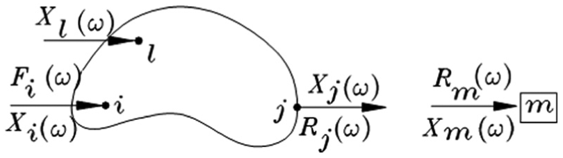
Free body diagram of the system.
In continue, governing equations of the system are as follows (equation (1))

where

where

where

Elimination of the reaction and displacements at the connection point results in 22

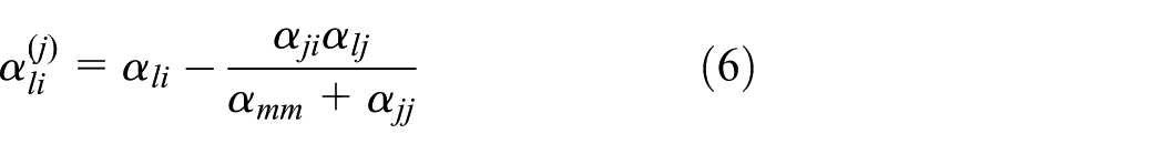
where

where
Equation (7) is the general equation for modifying a system by mounting a mass. There are two main applications for equation (7) in the mass cancelation which are suggested in this study:6,10
1. For the special case of an attached accelerometer, the point of response measurement is the same as the point of connection (j = l, l = −i). Then equation (7) can be simplified as follows

where
2. For the driving point accelerance (j = l = i), equation (8) can be rewritten as

where
Furthermore, in most cases, the excitation and response measurement at some structural points are impossible. To overcome the problem of obtaining

where
Strategy
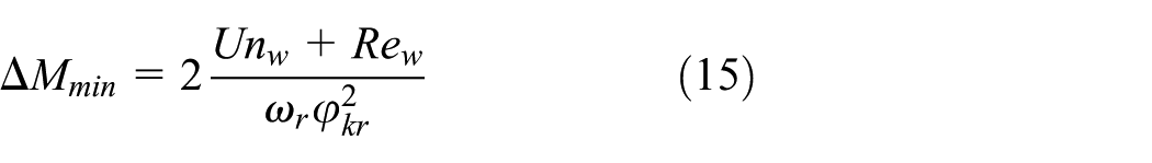
When more than one accelerometer is mounted on the structure, tests should be done for many times with extra masses in order to correlate mass-loading effect of all accelerometers.6,22 So, extra masses should be chosen in the way that the frequency changes can be measurable. It means that the change in frequency should be more than the uncertainties in the test. Besides that frequency resolution is considered in frequency change. It is suggested that amount of extra masses are estimated with FEM and sensitivity equations before testing. This helps in getting better results by repeating the tests. So, both uncertainties in measuring frequency (is calculated by repeating experimental tests) and frequency resolutions are considered as least frequency change. The amount of mass change is chosen on the basis of sensitivity equations. 23 Equation (11) is considered for sensitivity analysis

Then, variations in second power of natural frequency is calculated in equation (12) 23

So, changes in natural frequency is calculated in equation (13) 23

where

where
After obtaining the mass change, transfer FRFs which are used in equation (10) are chosen. Transfer FRFs are chosen because natural frequencies do not change in every transfer FRFs equally, and also, they may not be measurable because of the close distance between transfer FRF and node. So, it is suggested that the position of transfer FRF is chosen in the way that this position has an adequate displacement in every desirable modes in order to assure an adequate change in natural frequency. The optimum driving point (ODP) method is used for choosing the place of transfer FRFs. 24
The points which are near or exactly on the nodes are detectable in a known frequency range using ODP method because modal constants are almost zero in these points. In this method, shape functions are multiplied by each other in every degree of freedom (DOF) and considered as ODP parameter for each DOF. Equation (16) shows this method
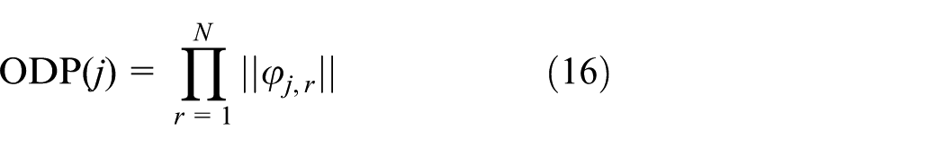
where
Finite element modeling of the structure.
Calculating
Choosing the amount of mass change (equation (15)).
Choosing an adequate accelerance with (equation (16)).
Simulation
A 5-DOF mechanical system with proportional dampers is shown in Figure 3. Such system is considered for verification of proposed method. The mass and stiffness matrices are obtained from the equations governing the system. The specifications of the system are given in Table 1.

A 5-degree-of-freedom system.
Parameters of the system.

DOF: degree of freedom.
Natural frequencies of the system without the accelerometer’s mass-loading effect are calculated by analyzing the eigenvalues of mass and stiffness matrices and they are given in Table 2, and Table 3 shows the extra masses which are chosen by suggested strategy.
Exact natural frequencies of the system with no accelerometer.

Amount of extra masses.

Eliminating the mass effect of accelerometer
In continue, accelerometers with the mass of 18 g are mounted on each of the masses that desired to eliminate mass effect of their corresponding accelerometer (equation (10)). Elimination of mass-loading effect is done in five steps. These steps are as follows:
Mounting extra mass on system in the first DOF (i = 1);
Performing a modal test and obtaining FRFs;
The mass cancelation of accelerometer is done using equation (10);
Calculation of natural frequencies from modified FRFs which are obtained from equation (10).
Performing steps 1–4 for next DOF (i = 2, 3, 4, 5).
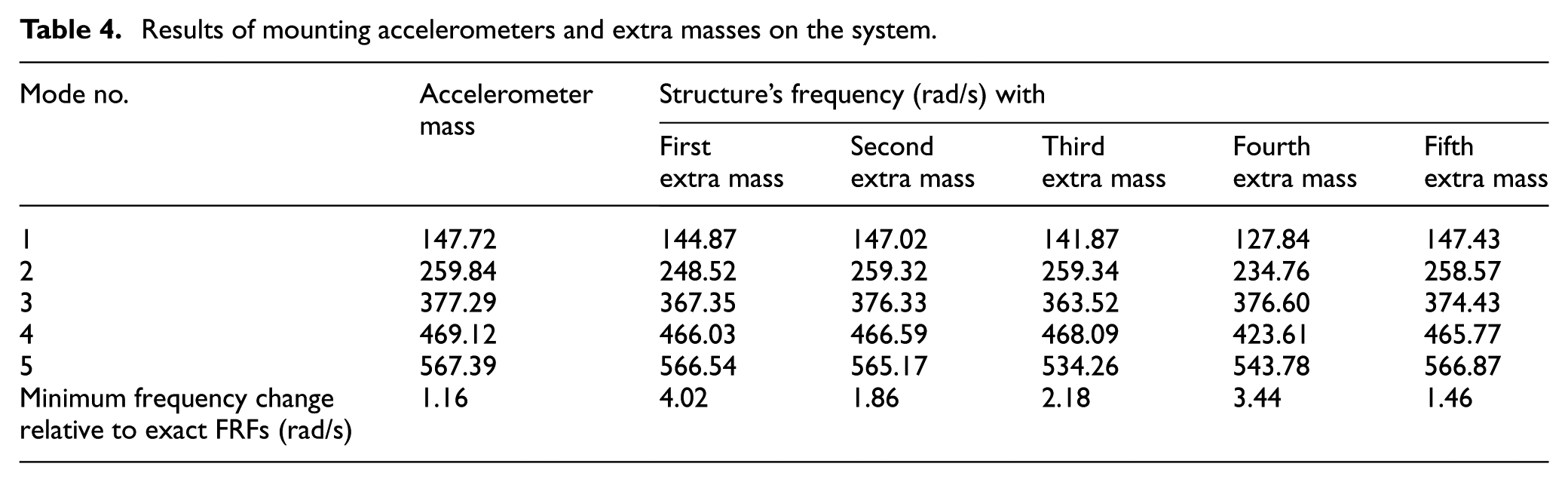
The dummy mass is attached to the preferred mass, and transferred FRFs that are chosen by equation (16) are calculated. The total mass-loading effects will be eliminated when the steps are completed. The results are given in Table 4. For example, FRFs corresponding to the third step are shown in Figure 4.
Results of mounting accelerometers and extra masses on the system.

FRFs with third extra mass.
Correlated frequencies are measured after using equation (10) and plotting modified FRFs using peak picking method (picking the peak of each mode shape). Results of this method are shown in Table 5.
Results of peak picking method on corrected FRFs (corrected FRFs are resulted from equation (10)).

After obtaining correlated frequencies, the amount of frequency change in each mode is calculated relative to the structure with accelerometer. In the case of linear structure, the required natural frequency change for eliminating mass effect is calculated by adding each natural frequency change corresponding to its mode in different steps. These results are given in Table 6.

If the amounts presented in Table 6 are summed with natural frequencies related to the case that accelerometers are mounted on the structure, then natural frequencies of the structure are obtained with no mass-loading effect of accelerometers. Errors in estimating natural frequencies are calculated in order to check the efficiency of the method. Such errors are shown in Table 7.
Comparing exact and corrected natural frequencies.

The effect of noise on the system
The measurements of test are usually affected by noise. Thus, in order to examine the noise effect on proposed method, a noise signal as random one was produced by MATLAB software and added to the FRFs of the structure using equation (17) 7

where

FRFs with 20% noise in first extra mass test.
The possibility of choosing the curve’s peaks and estimating natural frequencies will be vanished by rising the noise percent more than 20%. But as it can be seen in Figure 5, presented method tolerates the noise up to 20% and choosing natural frequencies is carried out using peak picking method.
Experimental investigation on the algorithm
Modal testing is performed on a plate with the dimensions 0.35 × 0.3 × 0.002. In order to estimate exact modal parameters of the structure, a lightweight accelerometer (6 g) of type DJB/A123E is mounted on the plate. Plate is excited with a hammer of type BK8202, and force signal is strengthened using an amplifier of type 2647A. The frequency range for the tests is chosen as 800 Hz, and frequency resolution is considered as 500 mHz. After measuring the driving force and acceleration, FRFs and coherence functions are estimated using the software Pulse 8 25 (Figure 6).

(a) FRFs in hammer test and (b) coherence functions in hammer test.
As coherence functions show (Figure 6(b)), hammer test has an adequate accuracy. So, these functions are given to the MODENT software, 26 and modal parameters of the structure are estimated and then modal parameters of the plate are calculated (Table 8).
Accurate plate frequency with one lightweight accelerometer.

Evaluating modal parameters of the structure with five accelerometers
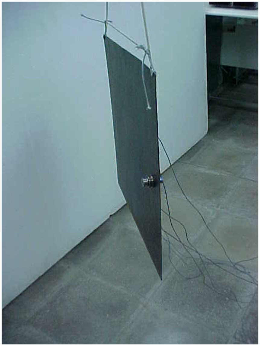
The main test in this part is conducted on the steel plate. There are eight accelerometers with 18 g masses and of type DJB/A120V. They are mounted on the plate as shown in Figure 7. The Modplan software is used in order to choose the best place for mounting such accelerometers. So, according to FEM of the structure and parameters such as ODP (equation (16)), the best points for placing accelerometers are gained by this software.
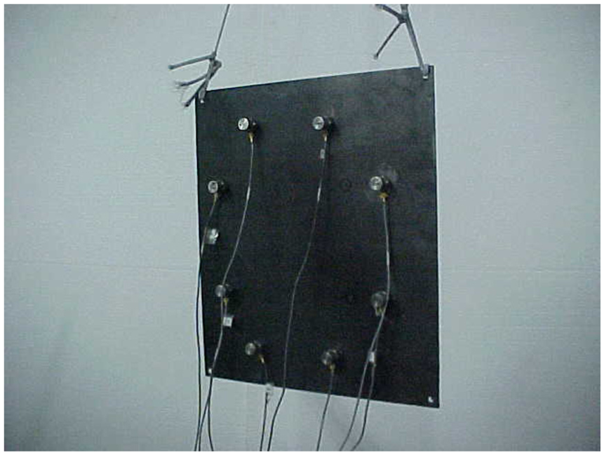
Plate under modal testing.
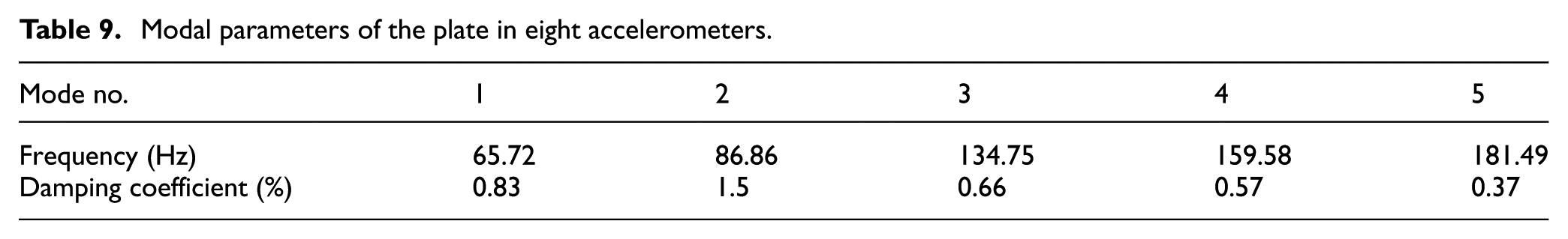
Plate is excited with hammer and then FRFs and coherence functions are calculated by measuring excitement force and acceleration (Figure 8). In continue, modal parameters of the system are gained by MODENT software (Table 9).
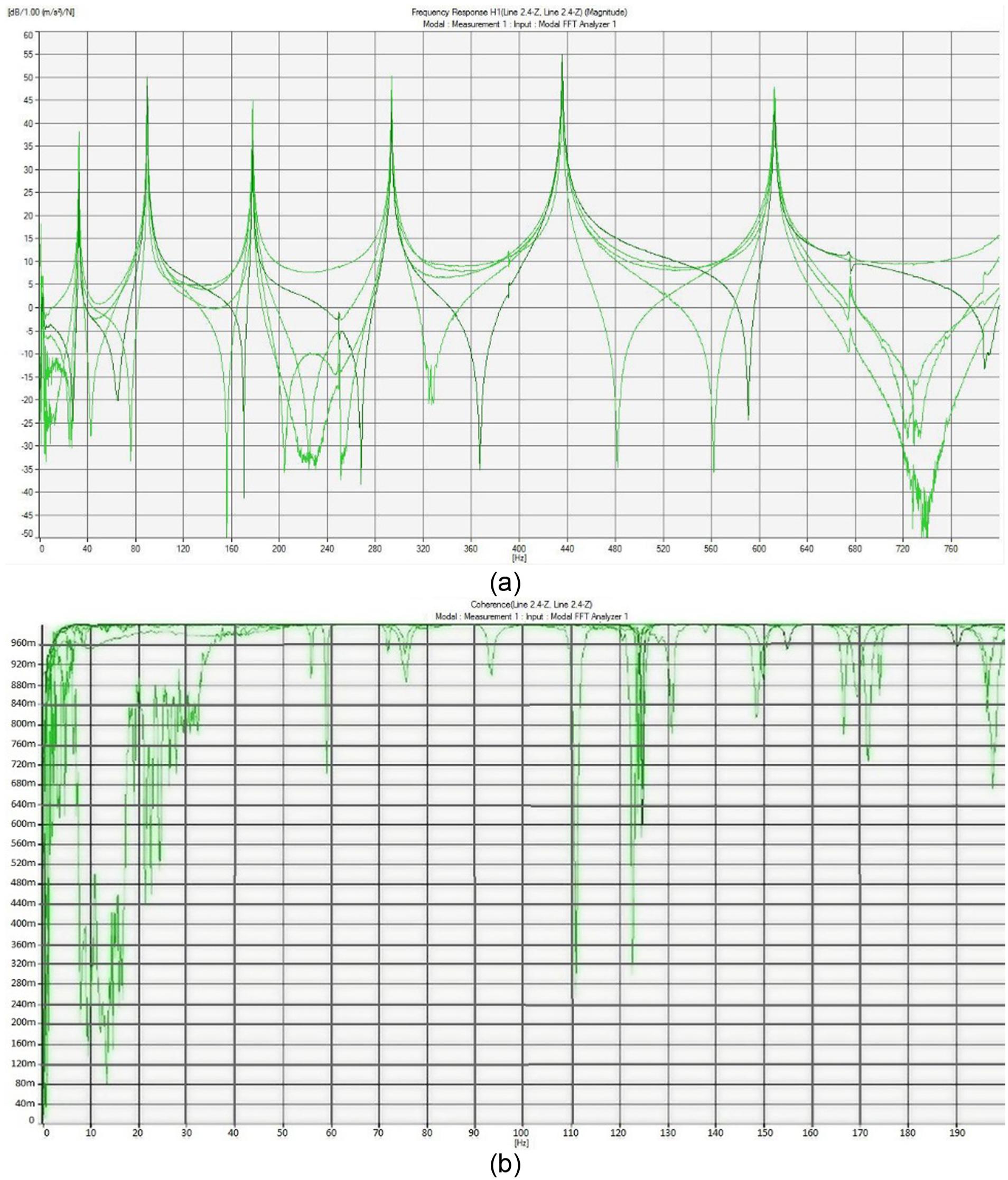
(a) FRFs in the hammer test and (b) coherence functions in the hammer test.
Modal parameters of the plate in eight accelerometers.
As shown in Tables 8 and 9, natural frequencies are changed according to the mass of the structure. Suggested strategy is used for eliminating mass-loading effect of accelerometers in the plate.
Mass cancelation algorithm
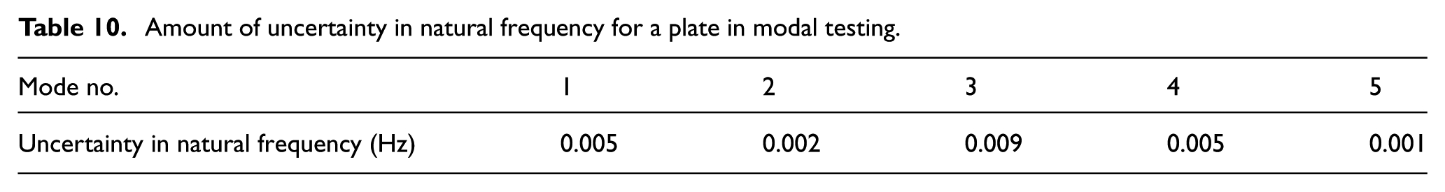
Equation (10) is used in order to cancel mass-loading effect of accelerometers, and equation (15) is used for choosing the amounts of extra masses. Modal testing is repeated many times to calculate uncertainty in measuring natural frequencies and then natural frequencies are obtained for each test. According to natural frequencies, the amount of uncertainty is calculated in each frequency, and these uncertainties are presented in Table 10.
Amount of uncertainty in natural frequency for a plate in modal testing.
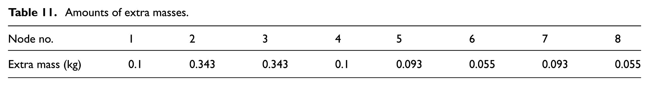
The amounts of extra masses are calculated by the amounts of uncertainty, frequency resolution (500 mHz), and FEM of the plate (Table 11).
Amounts of extra masses.
Eliminating mass-loading effect is done in eight steps. Extra mass is chosen from Table 11, then it is mounted on the plate in its place (Figure 9), and FRFs are calculated. This process is repeated for each step.
Mounting extra masses on each accelerometer.
Then mass-loading effect corresponding to the place of extra mass is eliminated from FRF by equation (10). By repeating this process to eighth accelerometer, mass-loading effect of all accelerometers will be eliminated. Results of these steps are presented in Table 12.
Frequency of structure (Hz) corresponding to extra mass and accelerometers on the plate.

After using equation (10) and plotting corrected FRF by peak picking method, corrected FRFs are measured. Results of this method are presented in Table 13.
Results of peak picking method on corrected FRFs (corrected FRFs which are resulted from equation (10)).

After calculating corrected frequencies (Table 13), the amount of frequency change in each mode is obtained according to the structure with eight accelerometers. The structure assumed to be linear, and the amount of required frequency change for eliminating mass-loading effect is obtained by summing frequency change in each mode and each stage. These amounts are calculated and presented in Table 14.
Amount of frequency change which is needed for mass elimination.

Results of the algorithm
If the amounts presented in Table 14 are summed with natural frequencies in the case that accelerometers are mounted on the structure, then natural frequencies of the structure are obtained with no mass-loading effect of accelerometers. Errors in estimating natural frequencies are calculated in order to check the efficiency of this method and then presented in Table 15.
Comparing accurate and corrected natural frequencies.

Conclusion
In this article, a strategy is presented for eliminating mass-loading effect from the results of modal testing. The amount of mass change is calculated on the basis of sensitivity analysis, in which the minimum change in natural frequency is obtained according to the uncertainty in measuring frequency and the frequency resolution. The place for measuring FRFs is obtained according to mode shapes in FEM. The results of such strategy show the efficiency of the algorithm in eliminating mass-loading effect of accelerometers in a structure. The experimental investigation is performed on the steel plate. Finally, both numerical and experimental results of this strategy have shown the efficiency and accuracy in elimination of mass-loading effect.
Footnotes
Academic Editor: Shimin Wang
Declaration of conflicting interests
The author(s) declared no potential conflicts of interest with respect to the research, authorship, and/or publication of this article.
Funding
The author(s) received no financial support for the research, authorship, and/or publication of this article.