
Abstract
This article investigates the change in deploying time of an active hood lift mechanism of a passenger vehicle activated by a gunpowder actuator. Especially, in this work, the deploying time is investigated by changing the principal design parameters of the hinge part of the hood mechanism. After briefly introducing the working principle of the active hood lift mechanism operated by the gunpowder actuator, the governing dynamic equations of the active hood lift mechanism are formulated for deploying motion. Subsequently, using the governing equations of motion, the response time for deploying the hood lift mechanism is investigated by changing several geometric locations such as the location of actuator. Then, a comparison is made of the total response time to completely deploy the hood lift mechanism with the existing conventional hood lift mechanism and the proposed active hood lift mechanism. In addition, the workable driving speed of the proposed active hood lift mechanism is compared with the conventional one by changing the powder volume of the actuator.
Keywords
Introduction
Because of the increasing awareness of pedestrian safety and strengthening the related regulations, certain mechanisms to reduce pedestrian injuries and prevent accidents have been greatly developing in vehicle systems.1–5 One of the advanced mechanisms to achieve this goal is to use an active hood lift mechanism (AHLM), which lifts the hood of an automobile when the vehicle collides with the pedestrian.6–10 The main role of the AHLM is to absorb the shock that would normally be transmitted to the pedestrian, like an airbag system in automobiles for the drivers. In other words, this mechanism makes the available deformation space of the hood at internal room by raising the hood for protecting pedestrian from colliding with hard structures such as the engine. In particular, this mechanism greatly reduces an injury of the pedestrian’s head, which causes the majority of fatalities. 11 It has been reported that when the AHLM is applied in a head impact test in vehicle driving speed of 40 km/h, the head impact performance criterion (HPC), which represents the injury value of the head, can be reduced by a maximum of 90%.6,12 Furthermore, it is assessed mathematically that the pedestrian lives of maximal 80% could be saved by the AHLM. 13 Recently, the latch part located at the front of the hood has also been considered to be important to achieve better performance, especially for the child pedestrian that collides with front area of hood. In the operation of the AHLM, the most important factor is the response time after the first collision to obtain minimum injury. Because a sufficient operational speed has not yet been achieved, the operation cannot be completed before colliding with the pedestrian’s head. Thus, a slow response time may cause a terrible impulse, including the kinetic energy of the hood, to be directly applied to the pedestrian. If the response (or deploying) time is reduced using a high operational speed, the AHLM can be operated even if the vehicle is driven at a higher speed.
More recently, a new AHLM activated by gunpowder has been introduced. It has been demonstrated that it could be operated at a vehicle speed of 60 km/h; in contrast, the conventional AHLM normally operates at less than 40 km/h.14,15 When the driving speed is 40 km/h, the necessary response time of the AHLM should be less than 60 ms from the worst case for protecting the child pedestrian.14,15 It is generally known that the sensing and processing time of an electronic control unit (ECU) is 30 ms, and the necessary response time of the conventional mechanism should be less than 30 ms in vehicle speed of 40 km/h. 16 However, when the driving speed is 60 km/h, the time from the first collision of legs to collision of the head should be less than 40 ms, and thus, the necessary response time of the AHLM should be sharply decreased to less than 10 ms. It is also known that the operating method using a gunpowder actuator has the best performance for reducing the response time of the AHLM. However, in order to enhance the deploying motion performance, a parametric study of the geometrical dimensions of the AHLM should be undertaken because many design factors directly affect the response time. Because of the potential variation in the explosive of the gunpowder actuator, the collision may occur before the operation in the worst case. The safety of mechanism should be increased maximally by changing the principal design parameters to reduce the response time. In addition, as mentioned, it is very important to study the design parameters of AHLM to reduce the response time in relation to fatal pedestrian accidents because the AHLM can protect pedestrians at a broader range of vehicle speeds by reducing the response time. Today, there is a sharp increase in the number of fatal accidents when the driving speed increases.17,18 It should be noted that lifting the hood higher in a shorter time can provide some benefits by absorbing the impact energy of the pedestrian. In other words, a pedestrian is protected more safely from the hard structure beneath the hood when the hood is lifted higher through the response time reduction. Recently, the authors studied the deploying time of the hood lift by considering latch part.20 However, despite the significance of the response time to deploy the hinge or latch part, to the best of the authors’ knowledge, a study on this issue is considerably rare.
The main technical contribution of this work is to investigate geometrical dimensions of the hinge part of the AHLM and hence identify the principal design parameters which can significantly reduce the deploying (or response) time in a collision with a child pedestrian. In order to achieve this goal, a mathematical model of the AHLM is first formulated for each deploying motion. In this formulation, the dominant design factors of the hinge part that are sensitive to the performance index are defined in the governing equations of motion. In the design process, the structural constraint conditions of the mechanism, such as the limited space, are defined in detail. Because the response time of the mechanism is an important factor for the system safety, the kinematic structure of the AHLM is newly designed to decrease the response time under the imposed constraint conditions. A comparison between the proposed AHLM and the conventional one is made in terms of the deploying time and deformation. It is shown that the newly designed AHLM can provide much faster deploying time and hence smaller deformation at several vehicle speeds and gunpowder volumes.
Working principle of AHLM
The photographs of the real operation of a passenger vehicle equipped with an AHLM are shown in Figure 1. The vehicle’s hood is raised immediately based on the sensor signal when it collides with an adult legform, as shown in Figure 1(b). The system raises both the front and rear of the hood to reduce the pedestrian impact using the AHLM installed at the latch and hinges of the hood. Two hinge parts of the AHLM deployed by the gunpowder actuator consist of several elements, as shown in Figure 2(a). It consists of several components named as bracket release, plate, and pole. Point A indicates a rotational joint that links bracket release and plate, named joint A. Point B indicates a rotational joint that links plate and car body, named joint B. It is noted that joint B is fixed to car body. Point C indicates a rotational joint that links bracket release and pole, named joint C. Point D indicates a rotational joint that links pole and hood, named joint D. It is seen that the vehicle hood can be raised by actuating the rotational motion of the components. When the pedestrian’s leg collides with the bumper of the automobile, the actuator is exploded based on the sensor signal. The actuator deploys upward when exploding, and bracket release is rotated in counterclockwise with causing the rotation of plate in counterclockwise through the rotational joint B. At the same time, pole contacts bracket release and rotates clockwise with causing the rotation of plate through the rotational joint C. And rotations of plate and pole cause the hood to lift through joint D. Figure 2(b) shows the final state of the hinge mechanism when the operation is completed. Therefore, the raised hood absorbs the impact energy of the pedestrian’s head before it makes contact with the engine.
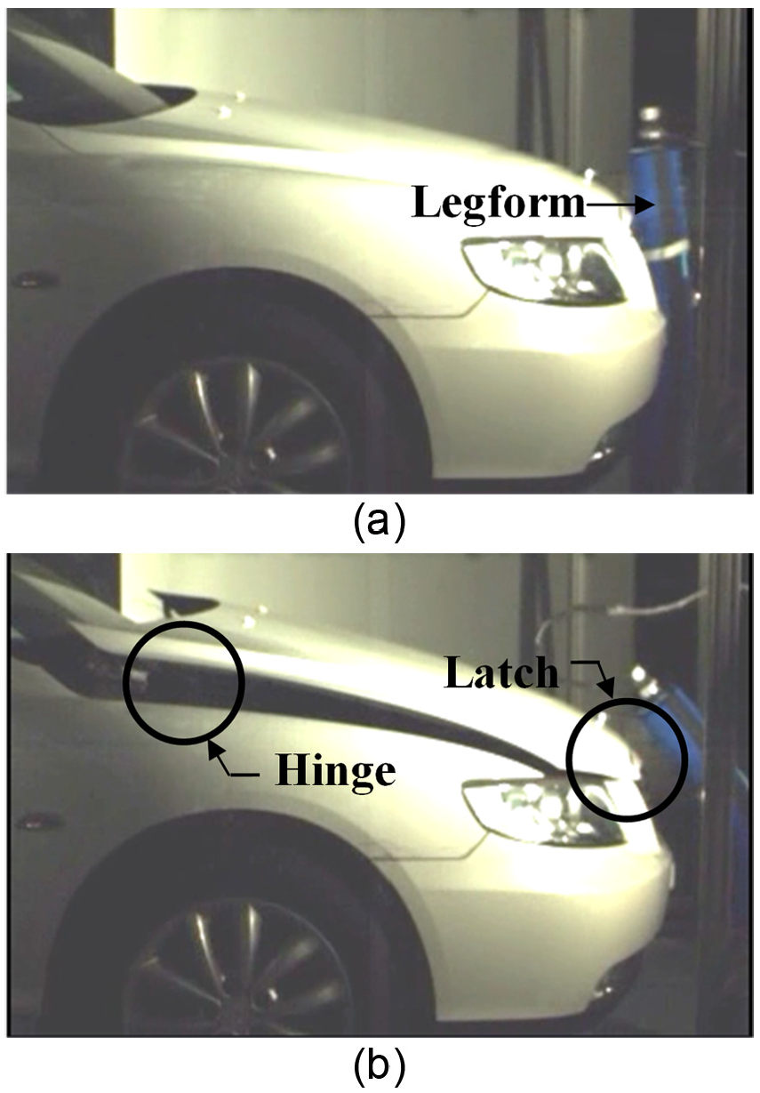
Operation photographs of vehicle equipped with AHLM (a) before and (b) after actuation.
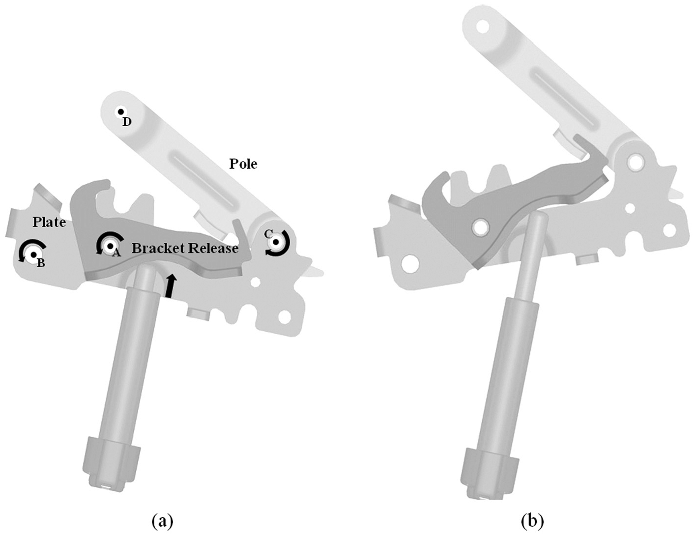
Schematic configuration of hinge part of AHLM (a) before and (b) after actuation.
In order to make it easier to understand the working principle, the operation sequence of the performance evaluation test of a conventional AHLM is shown in Figure 3. The white triangle indicates lifted height of the hood while the black triangle indicates the original state. In this test, the system lifts the hood by 50 mm when the operation is completed, which takes about 10 ms after the actuator starts the operation. The actuator is operated by a micro-gas generator (MGG) that quickly generates a large quantity of gas from the gunpowder. This system uses an MGG that produces a pressure of 65 MPa in a 10-cm3 volume when time passes 10 ms after the gunpowder is exploded.

Sequence of photographs of performance evaluation test.
Dynamic equations
The analytically derived governing equations of motion for the deployment of the AHLM are used to determine the operating speed and response time. The material properties used in this work are presented in Table 1. I1, I2, and I3 are the inertia moment of bracket release, the components that are rotated with plate, and pole, respectively.


Material properties of AHLM.


Pressure change by MGGs with different volumes: (a) pressure change in 35-MPa MGG with 10-cm3 volume and (b) internal pressure change in actuator with initial volume of 600 mm3.

Actuator force without volume change.

Schematic diagram of deployed distance of actuator.
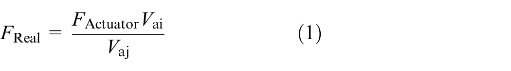
In the above, FReal is the real transmitted force, Vai is the initial internal volume of actuator, Vaj is the changed internal volume of actuator, A is the cross-sectional area of the actuator (38.5 mm2), R1 is 17 mm, and R2 is 41 mm. k is 75°.
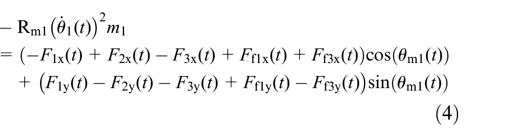
Figure 7 shows a free body diagram for solving the equilibrium equation of the force. Figure 7(a) presents a free body diagram showing the forces of bracket release and Figure 7(b) presents a free body diagram showing the friction force of bracket release. F1x and F1y are the force transmitted to bracket release by the actuator in horizontal and vertical directions, respectively. F2x and F2y are the force transmitted to plate by bracket release through joint A in the horizontal and vertical directions, respectively. F3x and F3y are the force transmitted to pole by bracket release in the horizontal and vertical directions, respectively. Ff1x and Ff1y are the friction force between the actuator and bracket release in the horizontal and vertical directions, respectively. Ff3x and Ff3y are the friction force between bracket release and pole in the horizontal and vertical directions, respectively. Rm1 is the distance from the rotation center of bracket release to the center of mass of bracket release, and the value of this distance is 20 mm.


Free body diagram for solving the equilibrium equation of the force: (a) free body diagram showing the forces of bracket release, (b) free body diagram showing the friction force of bracket release, (c) free body diagram showing the forces of pole, and (d) free body diagram showing the friction force of pole.
Figure 7(c) presents a free body diagram showing the forces of pole and Figure 7(d) presents a free body diagram showing the friction force of pole. Similarly, equilibrium equation for pole is derived, as follows
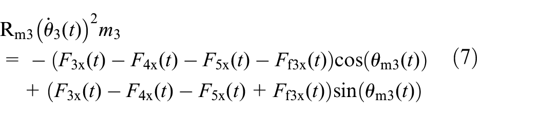
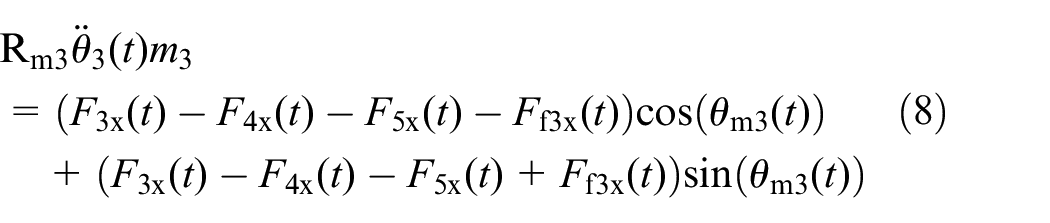

F4x and F4y are the force transmitted to plate by pole through joint C in horizontal and vertical directions, respectively. F5x and F5y are the force transmitted to hood by pole through joint D in the horizontal and vertical directions, respectively. Rm3 is the distance from the rotation center of pole to the center of mass of pole, and the value of this distance is 52.5 mm.


Here,

Relation of contact forces and forces in vertical and horizontal directions: (a) relation of F1 and F1x, F1y; (b) relation of F3 and F3x, F3y; (c) relation of Ff1 and Ff1x, Ff1y; and (d) relation of F3 and Ff3x, Ff3y.
Figure 9 shows the relations of those parameters, and those are mathematically given as follows


Relation of forces transmitted to hood and angular accelerations of elements: (a) relation of F5x, F5y and angular acceleration of pole and (b) relation of F5x, F5y and angular acceleration of plate.
In the above, mx is the mass of hood that is applied to one hinge mechanism in the horizontal direction. Because a vehicle’s hood is shifted in the horizontal direction by two hinge mechanisms installed on both sides of hood, mx is half of the mass of hood. my is the mass of hood that is applied to the one hinge mechanism in the vertical direction. The hood is shifted in the vertical direction by one latch mechanism and two hinge mechanisms. Because of the distance from the center of mass of hood to each place installed, mass of hood applied to one of hinge mechanism in the vertical direction is about a quarter of the mass of hood. R51 is the distance from joint C to joint D, and the value of R51 is 105 mm. R5d is the distance from joint B to joint D, and


Right-angled triangles that have an R51 and R52 with hypotenuse.
Here, R52 is the distance from joint B to joint C, and the value of R52 is 128 mm. The distances of the elements are denoted to calculate the moment of components for formulating the dynamic equation using the variables r11, r12, r21, r22, r31, r32, rf1, rf2, and rf3. r11 is the distance used to calculate the moment transmitted to bracket release by the actuator force. r12 is the distance used to calculate the moment transmitted to bracket release by the reacted force of pole. r21 is the distance used to calculate the moment transmitted to plate by bracket release through joint A and that is the distance from joint A to joint B. r22 is the distance used to calculate the moment transmitted to plate by pole through joint C and that is the distance from joint B to joint C. r31 is the distance used to calculate the moment transmitted to pole by the force of bracket release. r32 is the distance used to calculate the moment transmitted to pole by the reacted force of hood through joint D and that is the distance from joint C to joint D. rf1 is the distance used to calculate the moment transmitted to bracket release by the friction force between bracket release and actuator. rf2 is the distance used to calculate the moment transmitted to bracket release by the friction force between bracket release and pole. rf3 is the distance used to calculate the moment transmitted to pole by the friction force between bracket release and pole. Here, r21, r22, and r32 are fixed values and each value has 40, 128, and 105 mm. And the values of distances to calculate the moment of components, which change over time, are given as follows


Here, sa is the radius of arc that indicates a contact surface between actuator and bracket release, and the value of sa is 50 mm. And sb is a radius of arc that indicates a contact surface between bracket release and pole, and the value of sb is 25 mm. As shown in Figure 11(a), the point of contact between actuator and bracket release is shifted as following the arc that is presented by thick dotted line when the actuator is deployed. So the distance of r11 can be presented through the sine value of the l11 to express the change over time. And the rotational angle of the vertical line on the contact surface of actuator and bracket release is sum of rotational angles of bracket release and plate. r11i is the distance of r11 when the moment is transmitted at the first time. l11 is the line from joint A to point E that is the center of an arc, and the value of l11 is 65 mm. And r12 can be presented through Figure 11(b). Because the point of contact between bracket release and pole is shifted as following the arc that is presented by the thick dotted line in Figure 11(b), the distance of r12 can be presented through the sine value of the l12. r12i is the distance of r12 when moment is transmitted at the first time. l12 is the line from joint A to point F that is the center of an arc and the value of l12 is 71 mm. Here, the rotational angle of the vertical line on the contact surface of bracket release and pole over the shift of the contact point is set at


Distances to calculate moment of components which change over time: (a) r11, (b) r12, (c) r31 when moment is transmitted at the first time and (d) r31.
Figure 12 shows a free body diagram for solving the moment using the force and friction force. Figure 12(a) presents a free body diagram showing the forces for solving the moment of bracket release and Figure 12(b) presents a free body diagram showing the friction force of bracket release. Based on these free body diagrams, the moment equation of bracket release is derived using the sum of the moments, as given in equations (35). Figure 12(c) presents a free body diagram showing the forces for solving the moment of plate. Based on these free body diagrams, the moment equation of bracket release is derived using the sum of the moments, as given in equation (36). Figure 12(d) presents a free body diagram showing the forces for solving the moment of pole and Figure 12(e) presents a free body diagram showing the friction force of pole. Based on these free body diagrams, the moment equation of bracket release is derived using the sum of the moments, as given in equation (37)


Free body diagram for solving moment: (a) free body diagram showing forces of bracket release, (b) free body diagram showing friction forces of bracket release, (c) free body diagram showing forces of plate, (d) free body diagram showing forces of pole, and (e) free body diagram showing the friction force of pole.
Because the direction of F2n and F4n is the rotational direction of plate, F2n and F4n can be presented by F2x, F2y, F4x, F4y, and


Relation of the force in rotational direction of elements and force in vertical and horizontal directions: (a) relation of F2n and F2x, F2y; (b) relation of F4n and F4x, F4y; and (c) relation of F5n and F5x, F5y.
On the other hand, equation (35) is a kinematic relation between

Now, the unknown quantities of
The deployment is finished when the height of joint D that is linked to the hood increases by 50 mm in the vertical direction from the initial state. That time is defined as the response time of system. Because the height of joint D can be presented by the distance from joint B to joint D in the vertical direction, the lifted height of the hood, xh, can be presented mathematically as follows

Design parameters
Because bracket release and actuator are added to original hinge for lifting the hood, the location of actuator and bracket release is adjusted to reduce the response time. And the location of a contact point between bracket release and pole is also adjusted to improve the deploying performance. The distances that present three parameters are denoted as R1, R2, and R3 as shown in Figure 14 and all the distances to be adjusted for the new design are named “parameter distance.” R1 is indicated to the location of actuator, and that is the distance from a rotational center of bracket release to a contact point between actuator and bracket release in the horizontal direction. R2 is indicated to the location of bracket release, and R3 is the distance from the contact point of bracket release and pole to the rotational center of pole in the horizontal direction. All the distances to be adjusted to reduce the response time are directly related to several distances to set up the moment equations or other equations that is used to set up the governed equation. In this work, the independent influence on the response time is investigated by changing R1, R2, and R3 from −20% to +100% as given in Table 2. According to the table, the response time is reduced by increasing all the parameters in different ratios.

Distances of elements to be adjusted to reduce response time.
Response time due to change in parameter distance.

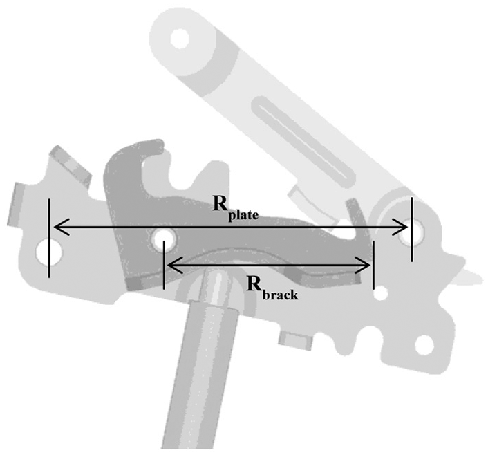
In the practical application of the AHLM, several geometric constraint conditions exist. Figure 15 shows a configuration of R1, R2, and Rbrack when the operation of the mechanism is completed. Rbrack is the distance of bracket release, and that is the distance from joint A to the end of the bracket release in the horizontal direction as shown in Figure 16. The geometric relation of distances can be expressed mathematically by the following equation


Geometric relation of distance of bracket release and parameter distances.
Distances of bracket release and plate.
As mentioned, k is the angle between deploying direction of actuator and horizontal direction. And


When Rbrack has the maximal value, the distance of arc in the horizontal direction is increased to R3 as shown in Figure 17(a). And


Schematic diagrams of
Figure 17(c) shows the relations of Rbrack, R3, and


It should be noted here that the value of
Results and discussions
A preferable structure for the AHLM to reduce the response time can be achieved by adjusting the design parameters of the hinge part. The suitable distances of R1, R2, and R3 are obtained based on the imposed geometric constraints. Because
Changing rate of R1 and response time due to changes in R2 and R3.

Comparison of response times of existing AHLM and newly designed AHLM with different actuator specifications.

MGG: micro-gas generator.
Workable driving speeds of existing AHLM and newly designed AHLM with different actuator specifications.

MGG: micro-gas generator.
Conclusion
In this work, an AHLM for a passenger vehicle that is deployed by the gunpowder actuator was introduced, and design parametric investigation to reduce the deploying (response) time was undertaken. In order to achieve this goal, the governing equations of motion were derived from free body diagrams as a first step. After carefully investigating the influences of the design parameters with geometric constraints on the response time, new values for the principal geometric design parameters that could provide faster response time were chosen for the AHLM. It has been demonstrated through computer simulations that the proposed AHLM with the new design parameter values can provide much better performance than the conventional one in terms of the total response time. In addition, it has been observed that the response time can be shortened by changing the volume of gunpowder. This directly indicates that the response time of the AHLM can be shortened through both the actuator capacity (gunpowder volume) and geometric values. It is finally remarked that a solid mathematical model integrated with optimization method to further reduce the deploying time with same constraints such as contact problem will be developed as a second phase of this work. Moreover, an experiment to evaluate the deploying time will be undertaken as a future work of this study.
Footnotes
Appendix 1
Academic Editor: Yangmin Li
Declaration of conflicting interests
The author(s) declared no potential conflicts of interest with respect to the research, authorship, and/or publication of this article.
Funding
The author(s) received no financial support for the research, authorship, and/or publication of this article.