
Abstract
This article deals with the reliability analysis and architecture definition of a fault-tolerant electro-mechanical actuator system for unmanned aerial vehicle applications. Starting from the basic layout of the flight control system of a medium altitude long endurance unmanned aerial vehicle, the attention is focused on the fault mode analysis of the single electro-mechanical actuator system, with the purpose of pointing out the effects of architectural choices on the system reliability. The electro-mechanical actuator system, developed to be a self-monitoring equipment, has three operating modes: normal, fail-operative and fail-safe. Reliability and safety budgets are quantitatively evaluated via fault tree analysis using typical failure rates of system components, and the most critical paths are identified and discussed.
Introduction
Electrically powered actuators are nowadays the reference technology for unmanned aerial vehicle (UAV) flight controls, and their applicability is quite proved in terms of performances.1–4 Electro-mechanical solutions allow to attain load, speed and dynamic response objectives, 5 but several concerns are still open in terms of reliability. In particular, the use of electro-mechanical actuators (implying less maintainability constraints, thanks to the elimination of hydraulic fluids) requires a cautious approach to safety issues, mainly for a lack of statistical database about components’ fault modes. 6 An effective counteraction is provided by redundant architectures managed by health-monitoring electronics, in order to obtain fail-operative and/or fail-safe actuators.7–10 With reference to a basic electro-mechanical actuator system (EMAS), composed of a control electronics, a power electronics, an electrical motor and a gear reducer, several strategies can be used to reach this goal. Mechanical redundancies can be employed in torque summing or velocity summing architectures.9,10 Electric redundancies can operate in multiple lanes for both control and power electronics.7,11 The choice about the number and the type of redundancies depends on the target reliability allocated to the actuator which, in turn, depends on the whole flight control system (FCS) architecture and its overall reliability. For example, the split of control surfaces into independent sub-surfaces, each one actuated by a single EMAS, makes the total loss of control (LOC) of the actuators less critical. System health monitoring with fault detection and isolation is also a key issue in order to make the EMAS operative in case of partial failure, or fail-safe in case of total LOC.12,13 Reliability analysis plays a fundamental role in this context, by identifying failure modes criticality and providing quantitative system failure rate evaluation.14–16
In this article, the reliability analysis has been carried out through the following steps. First of all, the cumulative probability for a catastrophic failure condition is defined, according to applicable airworthiness certification regulations for a medium altitude long endurance (MALE) UAV.17,18 The FCS layout is then chosen, in terms of number of control surfaces, each one actuated by a single EMAS. The possible FCS failure modes are analysed by a functional hazard assessment (FHA) to find the most critical condition and to derive the failure rate budget for a single EMAS. A possible EMAS architecture is therefore defined, in terms of number and type of internal redundancies. Finally, a fault tree analysis (FTA) is performed to evaluate the system failure rate and to compare it with the target budget. The most critical paths of the FTA are identified and discussed, by highlighting the EMAS components that are more relevant for the reliability level. A list of EMAS monitors capable of managing system redundancies and providing satisfactory failure coverage is finally given.
Safety budget allocation for UAV EMAS
Certification references
The design of an actuator for modern primary flight controls (i.e. implementing automatic and/or autonomous functions) is strongly affected by the safety requirements imposed at aircraft level by the airworthiness regulations. This issue is overemphasised in case of UAV applications, also for the lack of a unified certification reference. The NATO airworthiness certification regulation STANAG 4671:2009 17 is applicable to UAVs having maximum take-off weight (MTOW) in the range 150–20,000 kgf flying above non-segregated airspace, and its paragraph 1309 states that the cumulative probability of occurrence of catastrophic failure conditions shall be lower than 10−6 per flight hour. The Italian Ministry of Defence technical directive AER(EP)-P.6 18 also provides guidelines for the safety objectives of Italian Army UAV weighting more than 4000 kgf (Table 1). In particular, the cumulative probabilities of failures with catastrophic and hazardous effects are equal to those recommended by STANAG 4671, while the requirements are more relaxed for failures impacting on UAV reliability (i.e. with major or minor effects).
UAV safety objectives for flight on non-segregated airspace: comparison between Italian and US military regulations.

MTOW: maximum take-off weight.
The reliability requirements of safety-critical equipments derive from those at UAV-level (Table 1), and also depend on UAV architecture, that is, on the number of failure conditions determining an event with safety/reliability effects. For the preliminary design phases, the AER(EP)-P.6 document (used in this work as reference for the EMAS architecture definition) suggests to assume 100 catastrophic failure conditions, and to consequently scale all other objectives. This means that the probability of occurrence of a single catastrophic failure condition shall be budgeted at 10−8 per flight hour.
Flight control actuation system layout and EMAS failure rate budgeting
The work has been carried out with reference to the layout of the FCS of a MALE UAV developed by Alenia Aermacchi (see Figure 1). Provided that each surface is moved by a dedicated EMAS, the flight control functions are implemented as follows:
Roll control: performed by four ailerons, two per wing;
Pitch control: performed by three elevators on the horizontal tail;
Yaw control: performed by two rudders, one per each of the two vertical tails.

Flight control surfaces of the reference MALE UAV.
An excerpt of the preliminary FHA of the UAV FCS is given in Table 2, together with the evaluation of the derived EMAS failure rate requirement (λEMAS), once that the AER(EP)-P.6 safety/reliability constraints are applied. The calculation is made under the assumption that the EMAS is only affected by random faults (i.e. infant mortality and wear-out effects are neglected), so that its failure probability density is exponential. 19 The results demonstrate that the roll control function is the most critical one (Figure 2), and that the dimensioning criterion for EMAS failure rate is related to the total loss of 1 out of 4 ailerons.
Failure rate budgeting for the flight control EMAS.

EMAS: electro-mechanical actuator system; FHA: functional hazard assessment.
Partial loss is intended as a condition of performance degradation, but the surface motion is still safe.
Total loss is intended as a condition that causes a surface jam or unsafe motion.
Bold characters indicate the most stringent case for the maximum allowable EMAS failure rate requirement.

Example pf EMAS failure rate budgeting.
EMAS architecture definition
High computational resources are needed to perform the closed-loop control of EMAS, especially for current and speed loops. For this reason, these functions cannot be performed by the flight control computers (FCC), but they must be implemented by dedicated electronics. The control electronics can be integrated with the actuator, obtaining the so-called smart actuators, or separately installed into actuator control units (ACU). The latter approach has been used for the proposed EMAS, mainly to overcome installation problems: smart actuators have larger dimensions, which in some cases are not compatible with the airfoil thickness.
Functional requirements
In the reference application, the FCS has three FCCs handling the air data and inertial sensor signals. The FCCs exchange their data in order to process a common set of feedbacks and provide the EMAS with consistent operating mode and set-point commands. The operating mode and the set-point commands are the inputs which enable the EMAS to perform its two main functions: equipment health-monitoring and surface control.
Equipment health-monitoring function
With this function, the EMAS provides information to the FCCs about the health state of its parts and components. These feedbacks allow the FCCs to define the EMAS operating mode, which can be
Normal;
Fail-operative, corresponding to the ‘system reconfiguration’ mode, in which one or more faults to EMAS components have occurred, and they have been detected, isolated and (if applicable) compensated, so that the system maintains its performances to a satisfactory level;
Fail-safe, corresponding to the ‘system recovery’ mode, in which one or more faults to EMAS components have occurred, and they have been detected and isolated, and the system is configured to react to loads and environment without lowering the safety of the whole aircraft.
Surface control function
With this function, the EMAS provides motion control of the aerodynamic surface. In normal and fail-operative modes, this is obtained by a closed-loop control of the surface rotation, which assures static and dynamic performances (high accuracy and resolution, low hysteresis, adequate motion bandwidth and dynamic stiffness, while in fail-safe mode the function only implies that the actuator operates without lowering the aircraft safety.
The health-monitoring algorithms, executed at high rate both before and during flight (via Power-Up Built-In-Test and Continuous Built-In-Test, respectively), are performed within the ACU. In case of a detected failure, the ACU has the authority to set the EMAS in fail-operative or fail-safe mode, communicating to the FCC the health state. In case of lack of communication, the FCC has the authority to command the EMAS transition to the fail-safe mode.
Concerning the closed-loop control, it is digitally achieved within the ACU computing processor by three nested loops on EMAS position, motor speed and motor current. The loops run at different frequencies to guarantee adequate stability margins. Preliminary design studies provide evidence of the possibility of obtaining an EMAS position bandwidth of 7 Hz, by setting the sampling rate of current and speed loops at 10 kHz and the position loop at 500 Hz.
In the fail-safe mode, the proposed EMAS is designed to provide the surface with damping, in order to avoid catastrophic effects (e.g. flutter instability). This damping action is provided, once the motor is isolated from the electrical supply, by imposing the short circuit on its phases and by dissipating the regenerated currents on a bank resistor.
Qualitative CA of a simplex EMAS
In order to identify the most critical fault modes affecting the EMAS and to justify the proposed design solutions, a qualitative criticality analysis (CA) 19 is reported here with reference to a simplex rotary EMAS composed of the following:
A simplex digital ACU, performing closed-loop controls on motor currents, speed and position;
A three-phase permanent magnet synchronous motor;
A mechanical transmission from the motor to the aerodynamic surface;
Three current sensors (one per phase);
A resolver for the motor control;
A rotary variable differential transformer (RVDT) transducer for the rotation sensing.
The CA is developed following the approach used in Balaban et al., 6 by defining three groups of failure modes, depending on the component/assembly in which the fault occurs:
Electronic failures
Electrical failures
Mechanical/structural failures
As shown from Tables 3 to 5, each component/assembly fault mode is analysed, by defining the possible fault causes and providing an estimation of the following:
Fault probability of occurrence (FPO) during the operating time interval, defined selecting one of the following five levels:
19
Frequent (Level A) Reasonably probable (Level B) Occasional (Level C) Remote (Level D) Extremely remote (Level E)
Fault severity category (FSC) evaluated at EMAS level, defined selecting one of the following four categories:
19
System loss (Category I) System function loss (Category II) System function degradation (Category III) Unscheduled system repair or maintenance (Category IV)
Qualitative criticality analysis of a simplex EMAS (electronic components’ failures).
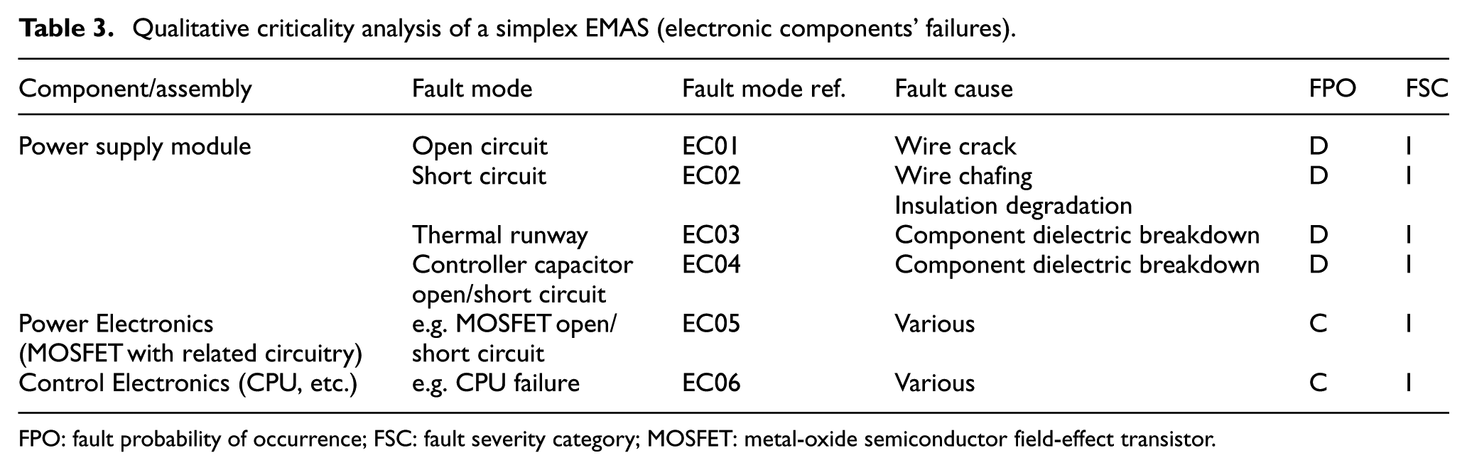
FPO: fault probability of occurrence; FSC: fault severity category; MOSFET: metal-oxide semiconductor field-effect transistor.
Qualitative criticality analysis of a simplex EMAS (mechanical components’ failures).
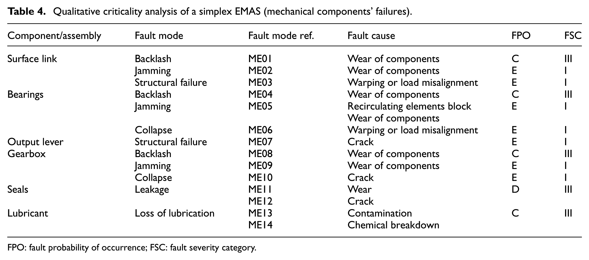
FPO: fault probability of occurrence; FSC: fault severity category.
Qualitative criticality analysis of a simplex EMAS (electrical components’ failures).
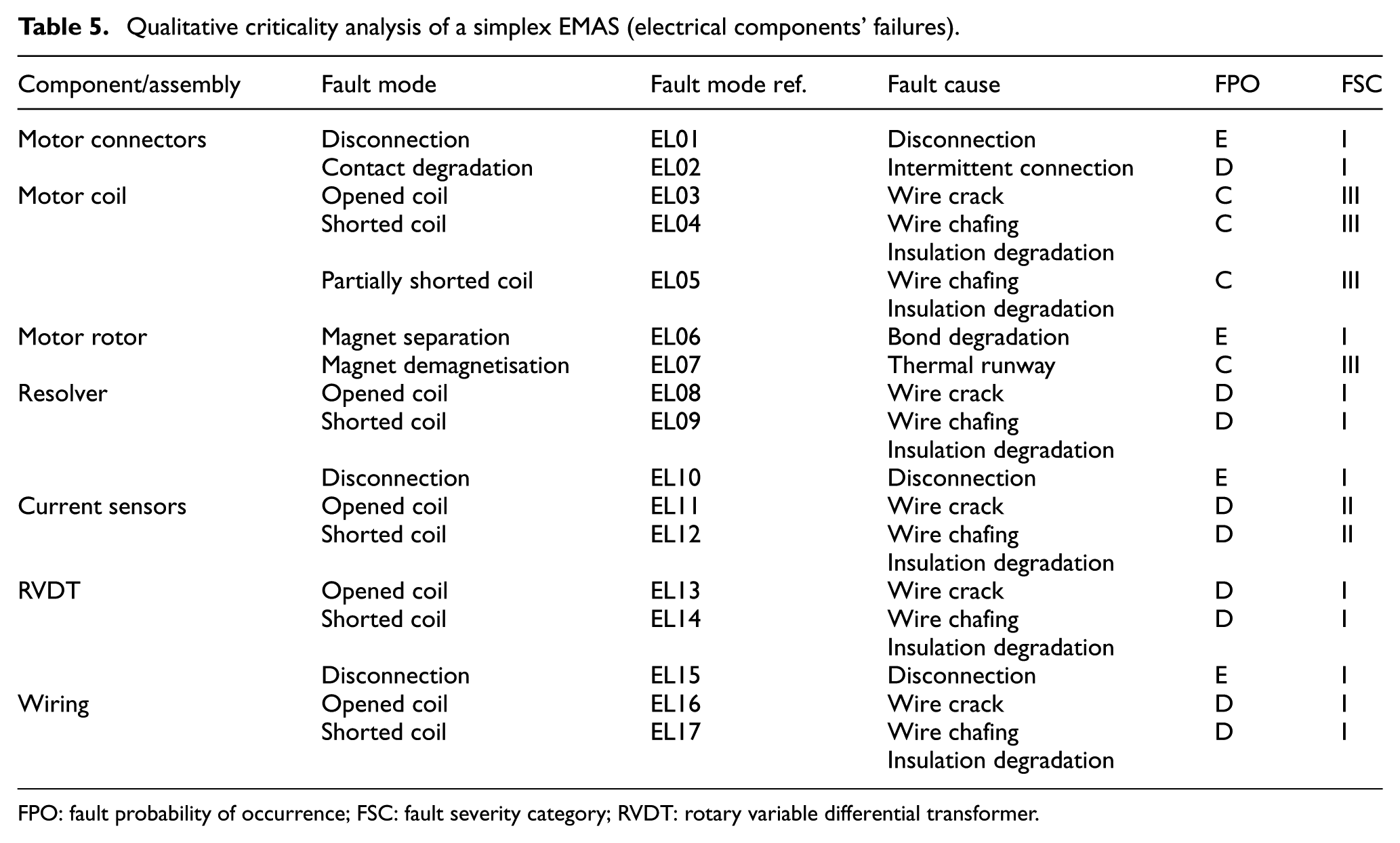
FPO: fault probability of occurrence; FSC: fault severity category; RVDT: rotary variable differential transformer.
The CA results have been then reported in the criticality matrix shown in Figure 3. The criticality matrix, synthetically comparing the fault modes in terms of severity and probability of occurrence, provides a tool for assigning corrective action priorities. In particular, the further along the diagonal line from the origin the fault mode is recorded, the greater the criticality and the more urgent the need for implementing corrective action. It is worth noting that the criticality matrix of the simplex EMAS has no fault modes classified as Category II, since the system has only one function and there is no difference between Category I and Category II. It can be noted that for a simplex EMAS, several corrective actions should be necessary to have chance of being safety compliant.

Criticality matrix for a simplex EMAS.
Proposed self-monitoring solution
As depicted in Figures 4 and 5, the proposed EMAS is composed of the following:
The ACU, including two independent computing sections, implementing health-monitoring (MON lane) and closed-loop control (CON lane); a power section modulating the motor coil currents, with three full H-bridges, each one dedicated to a coil, so that the motor is driven with isolated phases; a cross-lane data link (CLDL), for the data exchange between the lanes; a supply voltage sensor (SVS); a temperature sensor (TS), measuring the ACU operating temperature; three current sensors (CSa1, CSb1, CSc1), used for closed-loop controls; three current sensors (CSa2, CSb2, CSc2), used for monitoring algorithms; three voltage sensors (VSa, VSb, VSc) used for monitoring algorithms; a resolver (R) for the motor shaft rotation, used for closed-loop control; a transducer (RVDT1) of actuator rotation, used for closed-loop control; a transducer (RVDT2) of actuator rotation, used for monitoring algorithms.
The EMA, including three-phase permanent magnet synchronous motor with sinusoidal modulation; a two-stage gearbox for the mechanical power transmission.
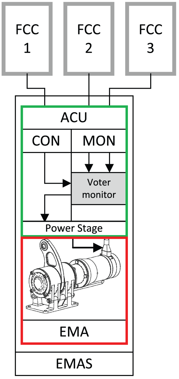
Interface between the EMAS and the FCCs.

Self-monitoring EMAS architecture.
The ACU CON lane, based on digital signal processor (DSP) technology, is able to manage both the EMAS sensor interfaces and the pulse width modulation (PWM) drive of the motor phases. The MON lane is based on an Advanced RISC Machines (ARM) processor, selected to implement hardware dissimilarity with the ACU CON Lane. The ARM processor has reduced computing performances if compared with the DSP, but it integrates two processors in lock-step configuration to improve the processor error detection (e.g. bus errors and memory errors).
EMAS health-monitoring algorithms
The three basic activities performed by the EMAS monitoring algorithms are as follows:
Fault detection: the operation of distinguishing between normal and failed behaviour, carried out by monitoring, processing and testing system measurements;
Fault isolation: the process of determining the failed component/subsystem that is responsible for abnormal behaviour after a failure has been detected;
Fault compensation: the process of responding to the failure to recover some level of system performance.
The following monitor algorithms have been defined to detect the fault modes analysed during the reliability analysis (a detailed description of the above-mentioned monitor functions is out of the scope of this work):
Outer loop monitor, which predicts, by means of a model, an expected EMAS response to inputs, in order to detect overall system malfunctions;
Current monitor, which performs a check of the current levels in the motor coils, to detect opened coils and to protect from over-currents;
Cross-lane current monitor, which performs a comparison between the motor currents measured by the CON and the MON lanes, to detect sensor faults;
In-lane monitors on RVDTs and resolver, which perform checks of the status of the sensors, to detect component fault;
Cross-lane position monitor, which performs a comparison between the positions measured by the CON and the MON lanes, in order to detect transducer faults;
Voltage supply monitor, which performs a check of the voltage supply level, in order to detect a voltage supply breakdown or a voltage sensor fault;
PSU temperature monitor, which performs a check of the PSU temperature level, in order to detect an abnormal heating of the PSU or a TS fault;
In-lane CPU monitors (watchdog) for both CON and MON lanes;
Cross-lane voltage demand monitor, which performs a comparison between the voltage demand for PWM calculated by the CON and the MON lanes, to detect CPU and I/O faults;
It is worth noting that combinations of these algorithms can be implemented for health-state definition at specific mission phases (power-up, pre-flight, etc.).
Effects of the architectural choices on the safety compliance
The safety concerns related to the application (Figure 3) are overcome by the proposed self-monitoring architecture. In particular,
the system reconfiguration covers the following faults (thanks to the phase-isolating electronics, the control loops are reconfigured and the motor works without performance degradation with only two coils): Electrical failures to the motor coils (EL03, EL04 and EL05, classified as C.III) and to the current sensors (EL11 and EL12, classified as D.II); The power electronics failures (EC05, classified as C.I)
the system recovery covers the following faults: Control electronics failure (EC06, classified as C.I); Resolver electrical failures (EL08 and EL09, classified as D.I); RVDT electrical failures (EL13 and EL14, classified as D.I); Wiring failures (EL16 and EL17, classified as D.I); Power supply failures (EC01, EC02, EC03 and EC04, classified as D.I); Magnet faults (EL06, classified as E.I, and EL07, classified as C.III); Resolver and RVDT disconnections (EL10 and EL15, classified as E.I).
All other EMAS faults can be covered via maintenance programme (e.g. all the jamming and structural failures) or by specific design solutions (e.g. standard rugged connectors).
Figures 6 and 7 show the FTA related to the total loss of the surface control (i.e. total loss of the EMAS), with reference to the simplex EMAS and to the self-monitoring solution. The failure rate data used in the FTA have been obtained from the literature20–23 by assuming 55°C operating temperature and airborne uninhabited cargo (AUC) environment (Table 6).

FTA related to the total loss of the simplex EMAS (failure rates × 10−6 pFH).
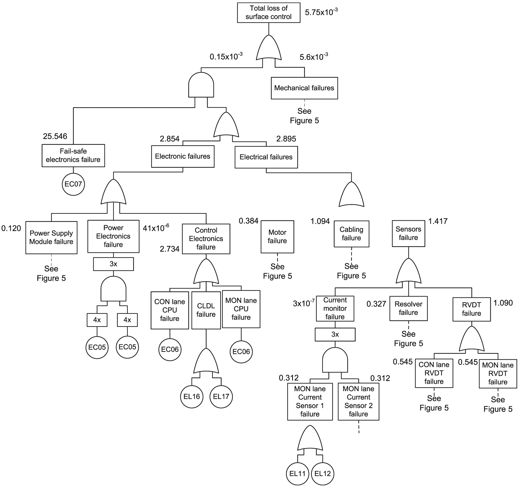
FTA related to the total loss of the self-monitoring EMAS (failure rates × 10−6 pFH).

RVDT: rotary variable differential transformer.
Additional electronics (switch assembly) for the self-monitoring solution.
The simplex solution has a 8.828 × 10⁻⁶ pFH probability of total loss of surface control (Figure 6), so it is completely inadequate for the application, due to the failure rates of the electronic and electrical sections (6.472 × 10⁻⁶ and 2.35 × 10⁻⁶ pFH, respectively). On the other hand, the self-monitoring solution (Figure 7), with a 5.75 × 10⁻⁹ pFH probability of total loss of surface control, is safety compliant (Table 2). The FTA highlights that this result has been obtained by adding the fail-safe electronics, which, in case of electronic or electrical failures identified by the health-monitoring algorithms, allows to isolate the motor from the electrical supply and to impose the short circuit on its phases (for aerodynamic surface damping). This design thus implies that the EMAS safety level is essentially driven by the mechanical failures, characterised by 5.6 × 10⁻⁹ pFH probability of occurrence.
Conclusion
The architectural design of a fault-tolerant EMAS for MALE UAV’s is discussed. Starting from a survey on available airworthiness certification references in case of flight on non-segregated airspace, the safety objectives at EMAS level are defined, and a qualitative CA is performed on a simplex EMAS, to identify the fault modes and causes and to classify their probability of occurrence and severity level. The proposed architecture overcomes the safety concerns of the simplex solution by using redundant components managed by a health-monitoring electronics. The EMAS actually includes two independent computing sections, implementing monitor and closed-loop control functions, and a phase-isolating power electronics. Thus, the actuator has three operating modes: normal, fail-operative (in which the EMAS is capable of operating with two out of three motor coils) and fail-safe (in which the motor phases are shorted and the regenerated currents create a damping torque on the control surface). To verify the effectiveness of the architectural choices, a quantitative evaluation of the probability of total loss of the surface control is performed via FTA on both the simplex and the self-monitoring solutions. The analysis highlights that the failure rate of the simplex solution (8.828 × 10⁻⁶ pFH) is inadequate for the application due to the high failure probability of the electronic and electrical sections. On the other hand, the proposed self-monitoring solution demonstrates to be safety compliant with a failure rate (5.75 × 10⁻⁹ pFH) that is essentially driven by the mechanical failures.
Footnotes
Acknowledgements
The authors wish to thank Dr Paolo Serena Guinzio and Dr Germana Vinelli of Alenia Aermacchi for their support to the activity.
Academic Editor: Nam-Ho Kim
Declaration of conflicting interests
The author(s) declared no potential conflicts of interest with respect to the research, authorship, and/or publication of this article.
Funding
The author(s) disclosed receipt of the following financial support for the research, authorship, and/or publication of this article: The research developed in this article was financially supported by Alenia Aermacchi (Research Contract no. 11-0426, 6th September 2011).